Contribution of Different Elements of Inclined Trash Racks to Head Losses Modeling


1
Institut Pprime, CNRS—Université de Poitiers—ENSMA, Pôle R & D écohydraulique OFB-IMFT-PPRIME, UPR 3346, 11 Boulevard Marie et Pierre Curie, Site du futuroscope, 86073 Poitiers, France
2
Office Français de la Biodiversité—DRAS, Pôle R & D écohydraulique OFB-IMFT-PPRIME, 2 Allée du Professeur Camille Soula, 31400 Toulouse, France
*
Author to whom correspondence should be addressed.
Water 2020, 12(4), 966; https://doi.org/10.3390/w12040966
Submission received: 14 February 2020
/
Revised: 17 March 2020
/
Accepted: 19 March 2020
/
Published: 29 March 2020
(This article belongs to the Special Issue Fish in Hydropower Affected Rivers)
Abstract
:Low bar spacing trash racks have been widely investigated in order to guide fish toward bypasses. In addition to this biological function, the formulae to predict head losses, for hydropower plants, are still being discussed. This paper investigates and models the global head losses generated by inclined trash racks with six different bar shapes and two different supports, in an open channel for six angles and two low bar spacings. The girders that supported the trash racks were U-shaped and different profile shapes. In addition to the previously studied rectangular and “hydrodynamic” bars, four new bar shapes, combining different leading and trailing edges, were investigated. Water depths were measured upstream and downstream of the rack for each configuration, and head loss coefficients were characterized and modeled. Three of these new bar shapes generated lower head losses than the hydrodynamic bar shape. The most efficient bar profile reduced the shape coefficient by 40% compared to the hydrodynamic profile and by 67% compared to the conventional rectangular profile. Concerning the supports, the use of a profiled girder to replace a conventional U-shaped girder also significantly reduced the head losses. The addition of the girder effect in a global formula increased its accuracy in predicting head losses of inclined trash racks upstream of hydropower plants.
1. Introduction
Hydropower plants are increasingly requested to include fish protection devices to limit the damages related to fish passage through the turbines, notably in Europe according to the Water Framework Directive (2000/60/CE). In this context, numerous studies have been done on downstream fish migration to ensure the right fish guidance towards bypasses and to optimize the energy loss due to these structures [1,2,3,4]. In particular, inclined and low bar spacing trash racks can be an efficient solution as evidenced by the high rates of safe fish transfer already achieved at several sites [5,6]. Concerning the prediction of head loss across the trash racks, the models are still progressing [7,8,9]. The hydraulic state is dependent on the bar profile, spacing, angle of orientation or inclination, and approach velocity [10]. With the aim of enhancing the existing formulation, which predicts the head losses in the case of inclined racks, this study investigates the contribution of two elements: the bar profiles and the transverse girders. At a low head hydropower plant, conventional trash racks installed to protect the turbines generally present large bar spacings (higher than 50 mm) and a rectangular bar profile. Achievement of fish friendliness requires now to reduce the bar spacing (equal to or lower than 20 mm) and consequently raises the issue of head losses and clogging. This is why new bar profiles, with more or less hydrodynamic shapes, have recently been proposed by manufacturers to lower the head losses.
The effect of the bar shape is generally represented by a shape factor (K) representing the contribution of a given bar profile in the head loss formulae. Several studies like Mosonyi (1966), Zimmermann (1969), and Meusburger (2001) used the coefficients defined by Kirschmer [11,12,13,14]). Clark (2010) and Raynal (2013) defined their own coefficients [4,15], and Spangler (1929), Idelcik (1979), and Escande (1947) integrated the effect of bar shape into charts [16,17,18].
Conventional trash racks are also generally almost vertical and perpendicular to the flow direction. For the fish guidance toward the bypasses, it is now recommended to incline or angle the racks. In the case of inclined racks, the size and the number of transversal elements (spacers between bars and girders) have increased to support the rack correctly. However, the effect of these transversal elements on head losses is still unexplored and poorly taken into account, or even ignored in existing formulae. The supports have been mostly tested in the case of structural designs. In fact, Scruton [19] studied the effect of wind in various shapes including the U and profiled shapes. The effect of these structures as support girders in hydrodynamic flows has not been studied until now, in particular as a component of trash racks. This paper aims to model the effect of different elements of trash racks, such as bar shapes and transversal supports, on head losses in hydrodynamic flows.
The first section presents the setup where the experiments were conducted and the methodology of the modeling. The second part focuses on the results for each of the addressed purposes of the study: the bar shapes and the supports. The models are then presented. The last part sums up the main findings.
2. Materials and Methods
2.1. Experimental Setup
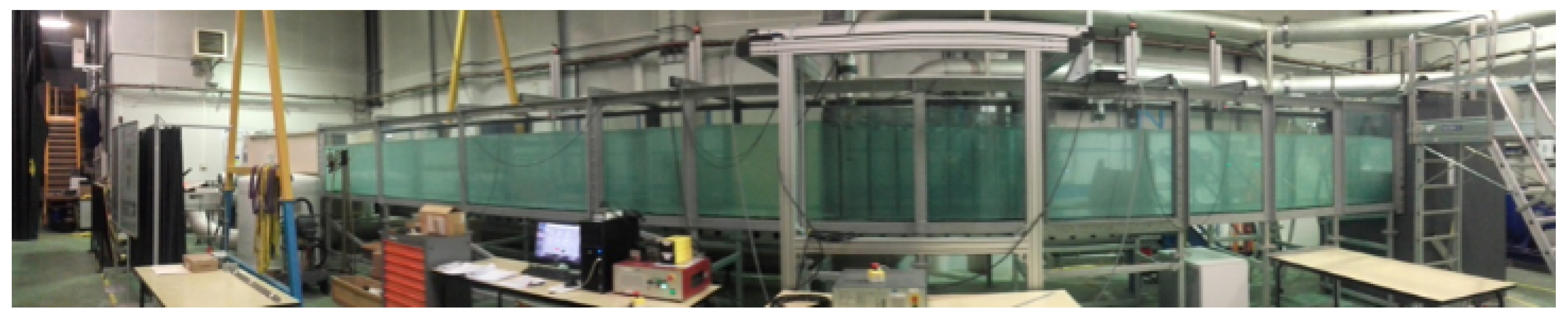
The experiments were conducted in the 1 m wide, 1 m deep, and 12 m long, open channel of the Pprime Institute of PVC bed and glassed side walls (Figure 1). A weir at the outlet of the flume served to adjust the head water. For this study, the upstream water depth () was fixed at 0.7 m for the angles equal to or higher than 35 and at 0.42 m and 0.67 m for, respectively, the angles of 15 and 25. The maximum flow rate was adjusted between 0.29 and 0.5 to obtain the same approach velocity () equal to 0.72 m (Table 1).
According to previous studies [7,20], the head loss coefficient is invariable for a Reynolds number higher than 3000 and for a Froude number higher than 0.1. In our experiments, the Froude number ( with g the acceleration of gravity) varied between 0.27 and 0.35, and the Reynolds number due to the bars based on the bar thickness (b) ( with the water kinetic viscosity) varied between 3600 and 8640.
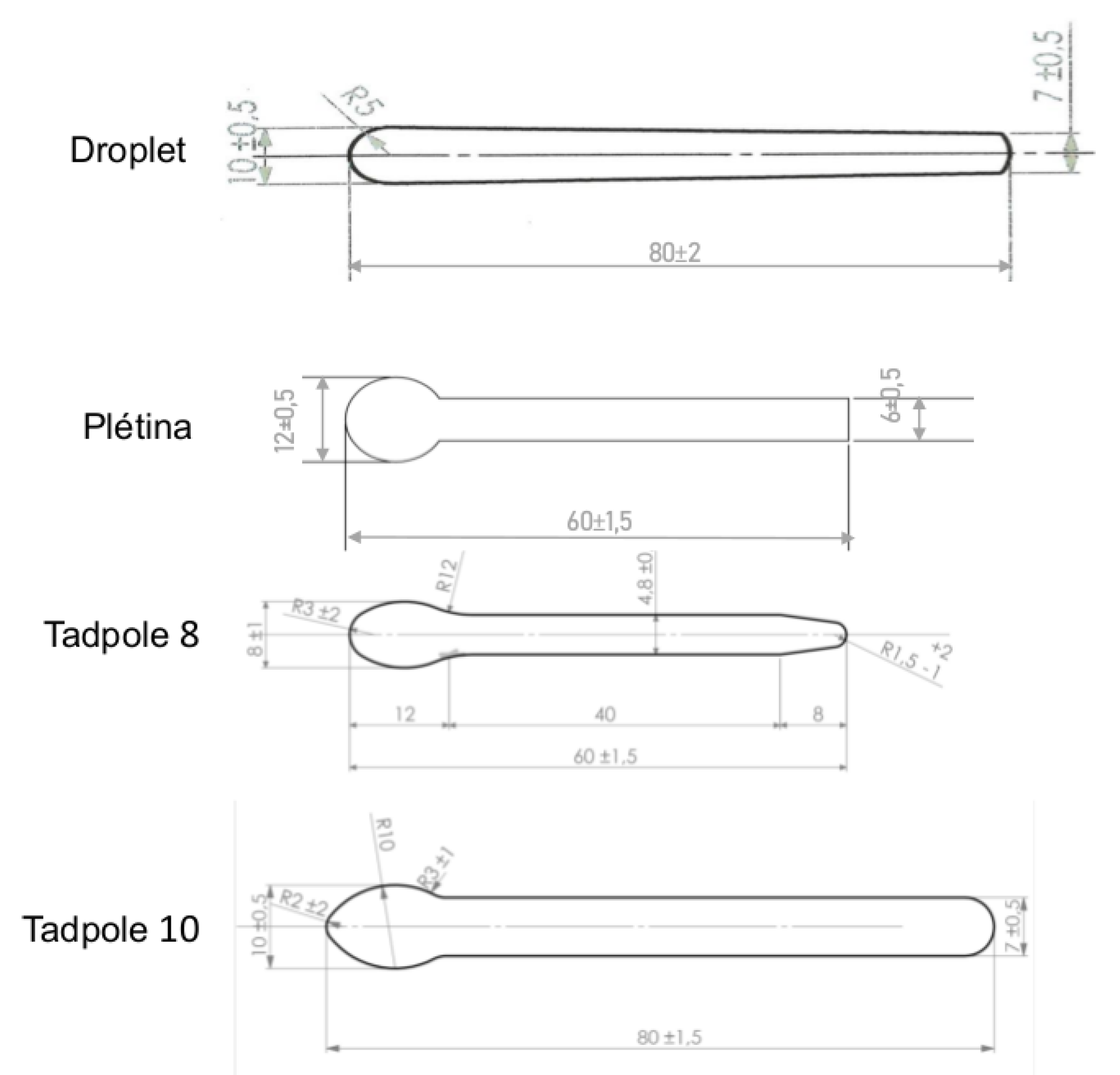
The trash racks were composed of three elements (Figure 2): the bars, the spacers, and the support elements. Six bar profiles were tested: Droplet, Plétina, Tadpole 8, Tadpole 10, and the hydrodynamic (PH) and rectangular (PR) shapes by Raynal were described in [4]. The different bar profiles are depicted in Figure 3, and their respective parameters are listed in Table 2. The lateral supports, which had the same thickness, were U and profiled shapes (Figure 4).
Each bar shape was tested with spacers of two diameters (21.2 mm/31.8 mm) resulting in a bar spacing depending on their dimension: for Droplet (20.2 mm/30.8 mm), Plétina (17.2 mm/27.8 mm), Tadpole 8 (18.2 mm/28.8 mm), and Tadpole 10 (18.2 mm/28.8 mm).
2.2. Measurements
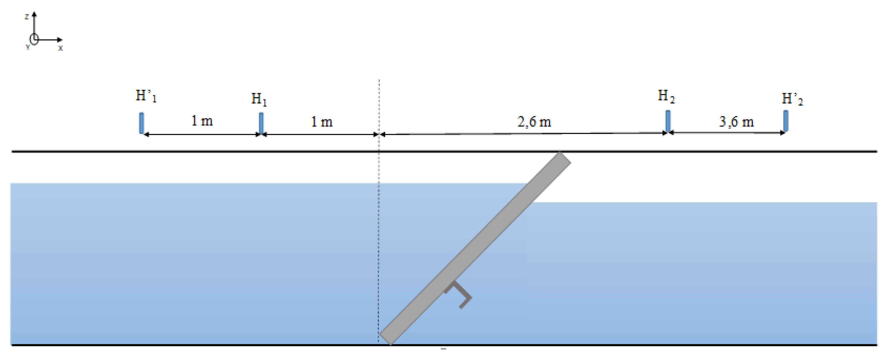
The water depth measurements were carried out using 4 ultrasonic water surface gauges (Microsonic Mic 35). They were respectively placed at 2 m () and at 1 m () upstream and at 2.6 m () and at 3.6 m () downstream of the trash rack, with respect to the upstream extremity of the trash rack at x = 0 (Figure 5). and were used to validate the measurements. These positions were identical to those used in previous studies [20]. The water level measurements consisted of 60 s recordings at a sampling frequency of 200 Hz. The water depth uncertainty was calculated with the index of [21]. First, several measurement sources of error were identified such as: the sensors’ calibration, the sensors’ support installation, the channel width measurement, and the flow rate measurement. Then, the head water standard uncertainty was evaluated with the law of propagation of the uncertainties [22] and varied between 1 and 3 mm.
2.3. Calculation
The mean upstream and downstream velocities were calculated, giving (B) the channel width (m) and the upstream and downstream water depths in Equation (1):
With Bernoulli’s equation, the head loss due to the trash rack was determined as presented in Equation (2):
Given that = 1.47 mm was the head loss measured without the trash rack in the channel, the head loss coefficient was then calculated in Equation (3):
2.4. Methodology of Modeling
2.4.1. Bar Shape
The second step was to model each bar shape by a specific coefficient. Raynal et al. (2013) [20] established a validated formula of the head losses generated by inclined trash racks explained in Equation (4):
Herein:
Herein, is the bar shape coefficient (-), the blockage ratio due to the bars (-), the blockage ratio due to the transversal spacers relative to the upstream water level (-), the number of bars (-), b the bar thickness (m), the upstream water level (m), the number of spacer rows (-), the spacer diameter (m), B the channel width (m), the inclination angle (), and C = 1.79 the spacers’ shape coefficient (-). Each term of the formula is explained in Equation (5):
Based on this formula, the bar coefficient is modeled by . Raynal et al. (2013) [20] determined = 3.85 for rectangular bars and = 2.10 for hydrodynamic bars. For each bar shape, the terms and were calculated according to the parameters above. Then, the head loss coefficient due to the spacers was subtracted from the total head loss coefficient .
2.4.2. Support
The effect of the supports on the head losses were also modeled. The formula of Raynal et al. (2013a) is recalled in Equation (6):
In order to model the head losses due to the supports, we subtracted the head loss coefficient with supports from the head loss coefficient without supports. The approach was then to add the term to Equation (6), which models the effect of these structures on the flow. The equation becomes:
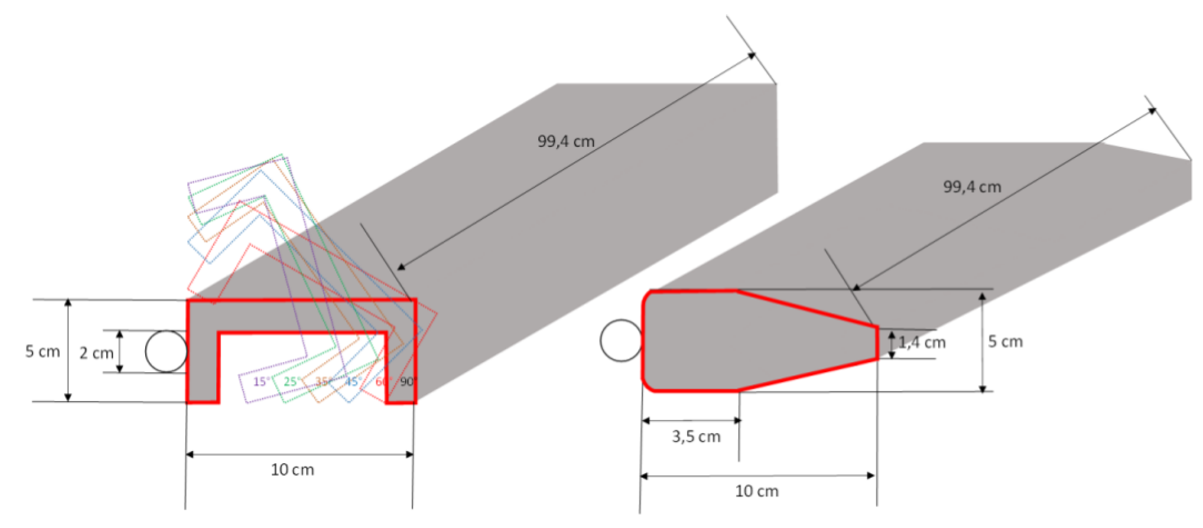
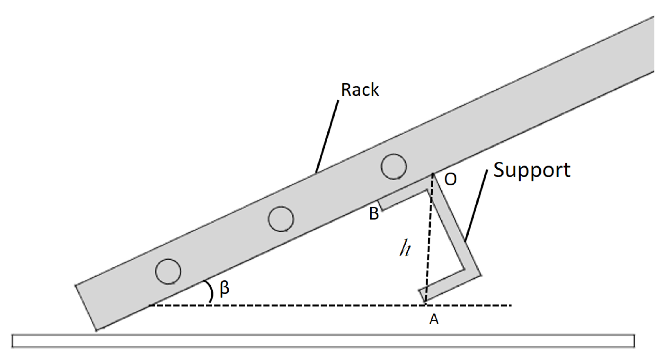
Then, the term (Equation (8)) is modeled through the different parameters: the projected support diagonal and the angle of inclination.
With h the projection of the support diagonal on the flow (m) and the upstream head water (m), and are respectively the U and the profiled shape coefficients (-), and is the support obstruction coefficient(-).
Figure 6 explains the calculation of the projection h of the support on the flow in the two cases:
- If profiled shape, h is constant.
- If U-shaped, .
The angle between the diagonal and an edge of the support was equal to .
The two support coefficients and were obtained from the adjustment of measured data. The diagonal projection depended on the angle of inclination for the U-shaped support. The profiled shape support coefficient was constant due to the same position kept in all inclinations during the experiments.
3. Results
3.1. Effect of the Bar Profiles on Head Losses
3.1.1. Experimental Head Loss Coefficients
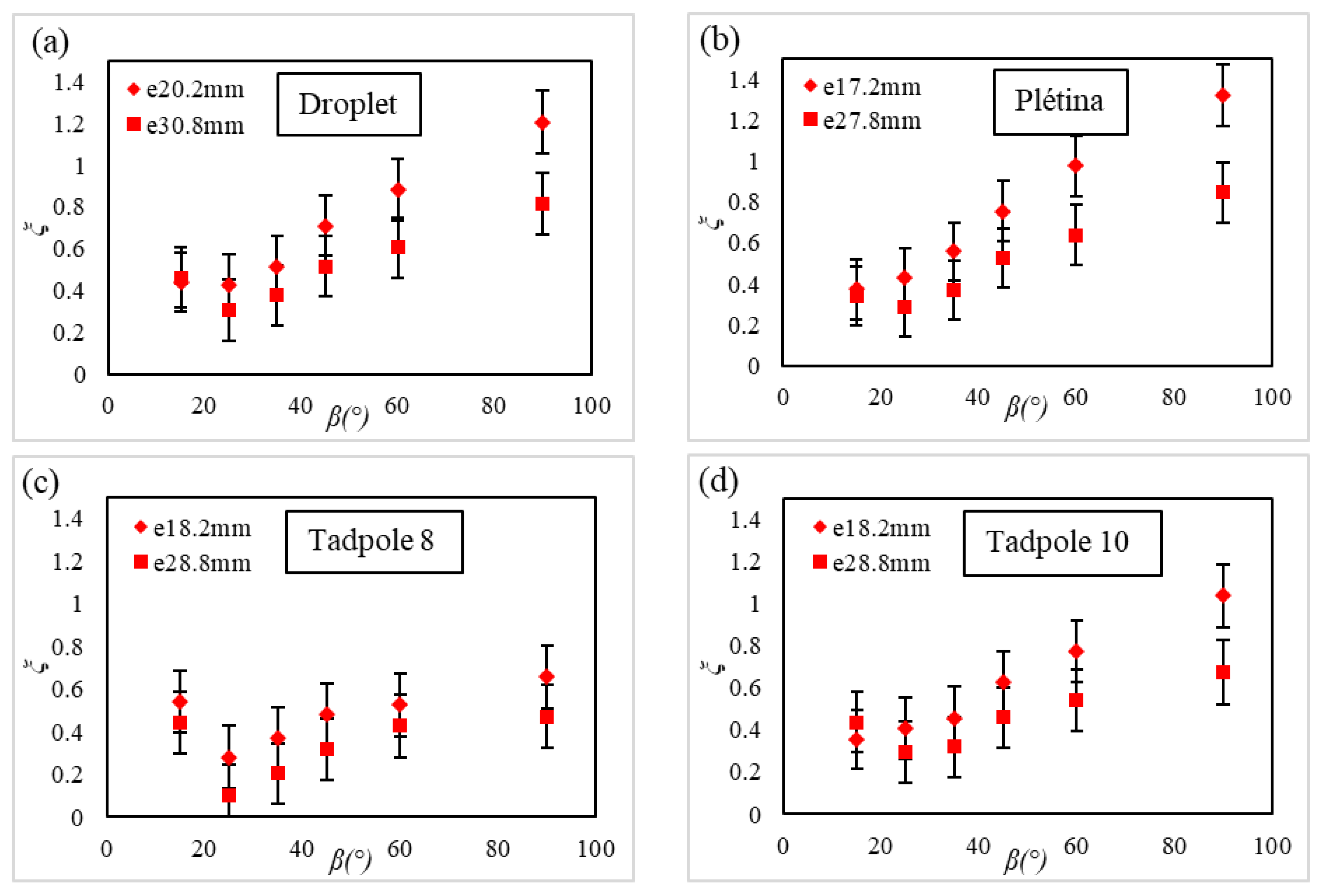
The head loss coefficient was represented according to the angle of inclination (15/25/35/45/60/90) and listed in Table A1.
Figure 7 shows that the maximum head loss coefficient increased with the angle of inclination, from 0.4 at 15 to 1.4 at 90 for the Plétina bar shape with 17.2 mm spacing. The minimum head loss coefficient increased with the angle of inclination, from 0.1 to 0.7 for the Tadpole 8 bar shape with 28.8 mm spacing. The trend followed by the measured points was similar between different bar shapes. The head losses decreased with the rack angle of inclination and increased when the bar spacing decreased. The lowest head losses were obtained for the Tadpole 8 profile. Indeed, the contraction of the frontal surface by the progressive reduction of the bar’s width and depth contributed to the diminution of the energy loss.
3.1.2. Modeled Head Loss Coefficients
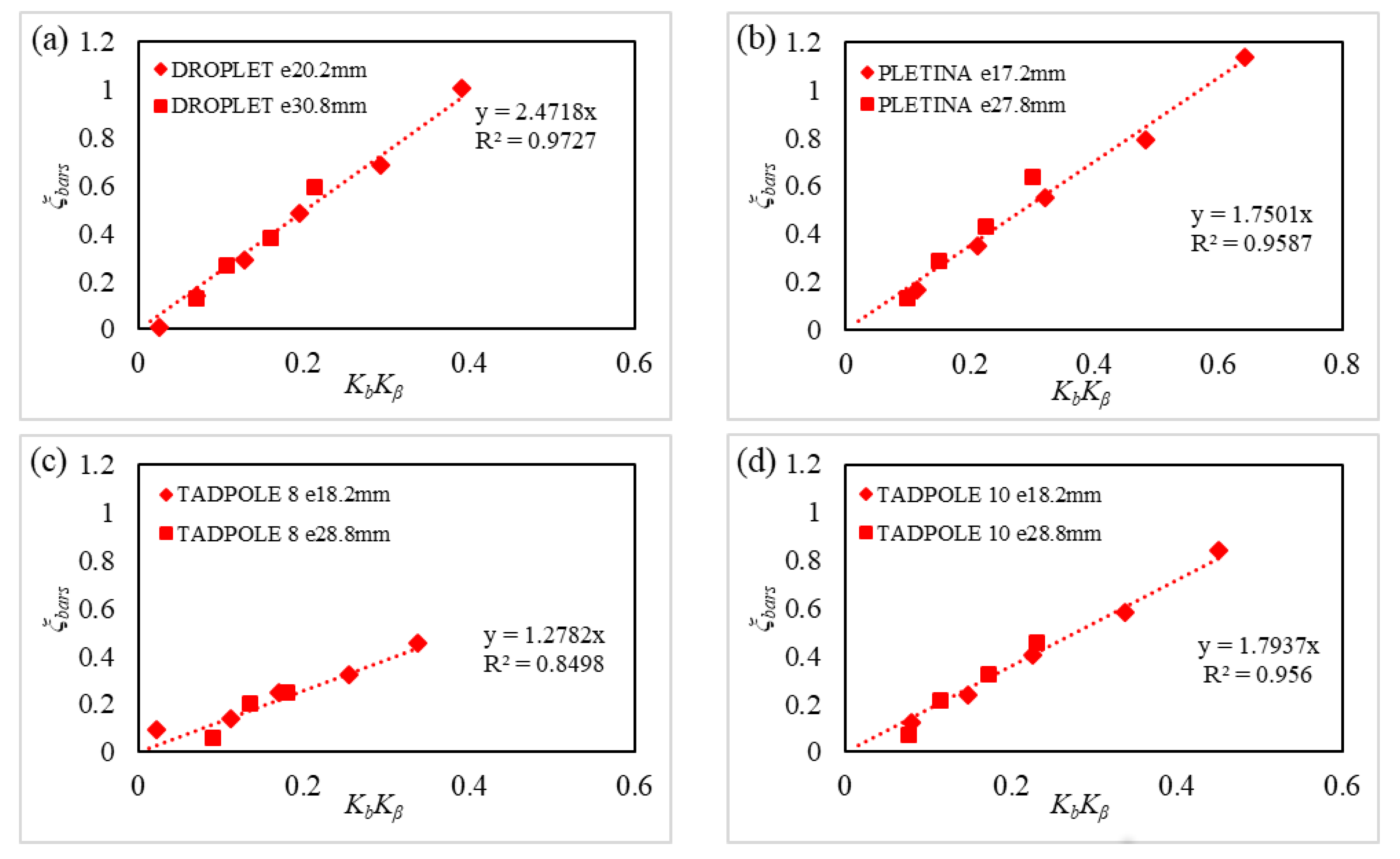
A linear regression was performed between and to determine the coefficient (Figure 8).
Table 3 sums up the values of the bar coefficients obtained by the linear regression. The increased linearly to , which allowed determining the coefficient . The Droplet shape had a coefficient equal to 2.47. The Tadpole 10, Plétina, and Tadpole 8 corresponded to coefficients of 1.79, 1.75, and 1.27, respectively. These coefficients were also compared to 3.85 for the rectangular shape and 2.1 for the hydrodynamic shape. These tested bar shapes generated lower head losses than the rectangular shape. The Droplet shape exhibited a slightly higher coefficient than the hydrodynamic profile, but was still less than the rectangular shape. To conclude, Tadpole 10, Plétina, and Tadpole 8 were alternatives to diminish head losses across trash racks, respectively by 53.5%, 54.5%, and 67% to the rectangular bar shape (Table 3).
3.2. Effect of the Support on Head Losses
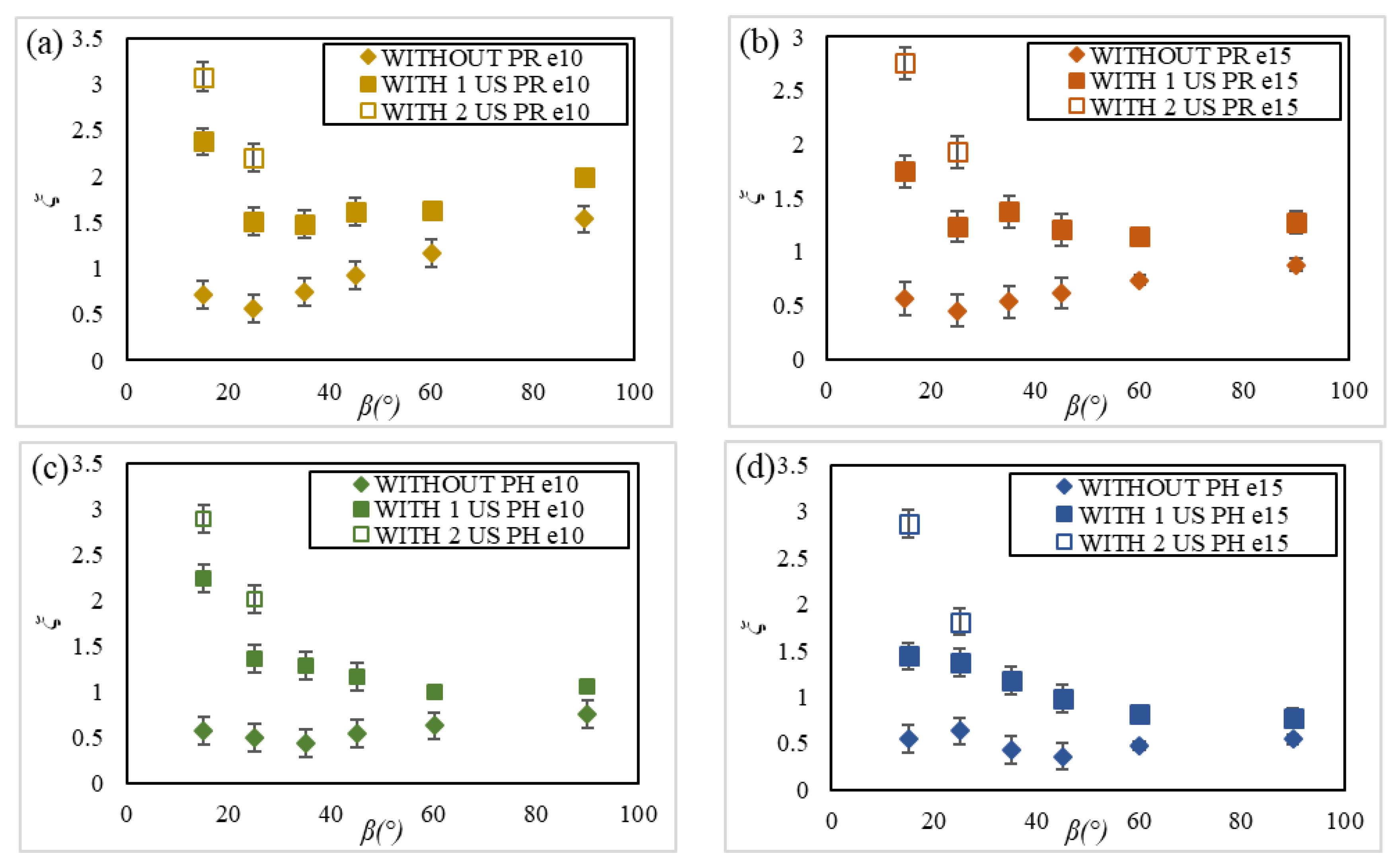
The inclined trash racks were tested with transversal supports. The first support was U-shaped, and the second was based on a streamlined profile. The results of the corresponding measured head loss coefficients are presented, each time with and without the supports, for two bar spacings (10 and 15 mm) and two bar shapes (rectangular (PR) and hydrodynamic (PH)), to observe the effect of these structures and listed in Table A2.
3.2.1. Experimental Comparison with and without U-Shaped Supports
Figure 9 shows the measured head loss coefficients as a function of the angle of inclination and the bar spacing e (10 mm/15 mm) for the two bar profiles (rectangular and hydrodynamic) with and without U-shaped supports. In sum, the addition of a single U-shaped structure multiplied the head loss coefficient by a factor of two to three and by a factor four to six with a second support.
3.2.2. Experimental Comparison with and without the Profiled Support
Figure 10 shows the measured head loss coefficients as a function of the angle of inclination and the bar spacing e (10 mm/15 mm) for the two bar profiles (rectangular and hydrodynamic) with and without one profiled shape support, streamlined to the flow in all rack inclinations. The influence of the profiled support resulted in a constant increase of the head loss coefficient of the order of 0.1 to 0.2. Therefore, this impact was lower than for the U-shaped support. This result would be modeled as an additional contribution in the formula of Raynal et al. (2013a) [20].
3.2.3. Modeled Head Loss Coefficients
Figure 11a shows that the estimation was acceptable since the measured points agreed linearly with the modeled points. The Pearson coefficient , equal to 0.81, indicated the reliability of the results of the U-shaped support. Figure 11b proves that the model for the profiled shape support fit the measured points with a Pearson coefficient of 0.956.
4. Conclusions
Head losses were investigated for fish friendly inclined trash racks in two aspects: bar shape and support. Four bar shapes (Plétina, Tadpole 8, Tadpole 10, Droplet), in addition to two previously studied (rectangular and hydrodynamic) and two supports (U-shaped and profiled) were tested for six angles and two bar spacings.
The newly tested bar shapes generated lower head losses than the rectangular one, and three of those generated lower head losses than the hydrodynamic one. The most efficient was the Tadpole 8 profile, reducing the shape coefficient by 40% compared to the hydrodynamic profile and by 67% compared to the conventional rectangular profile. These results highlighted the interest in the widening of the bar spacing just downstream of the leading edge of the bars and of a beveled trailing edge. The head losses were shown to increase significantly when the transversal supports were included. However, using a profiled girder reduced this effect compared to the U-shaped girder. The head loss formula was therefore upgraded to integrate the modeling of transversal supports and new bar shape coefficients. These contributions to the formula would help the hydropower producer rigorously assess the head losses of inclined trash racks in the case of low bar spacing and to choose the most cost-efficient bar shape and support profile. In the future, it will be interesting to verify the modeling of the head losses in real sites and to evaluate the consequences of the bar profile on clogging.
Author Contributions
Conceptualization, F.L., L.C., D.C., and L.D.; methodology, F.L. and L.D.; software, F.L.; validation, F.L. and L.D.; formal analysis, F.L.; investigation, F.L.; resources, F.L.; data curation, F.L.; writing—original draft preparation, F.L..; writing—review and editing, F.L., L.C., D.C. and L.D.; visualization, F.L.; supervision, L.C. and L.D.; project administration, L.C., D.C. and L.D.; funding acquisition, L.C. and L.D. All authors have read and agreed to the published version of the manuscript.
Funding
This project received funding from the European Union’s Horizon 2020 research and innovation program FITHydro(www.fithydro.eu), under Grant Agreement No. 727830. The authors acknowledge the financial support of the CPER-FEDER of the Nouvelle-Aquitaine region for the environmental hydrodynamic platform.
Acknowledgments
This study is part of a research collaboration for bar shapes with the company ALR under Grant Agreement No. 786606.
Conflicts of Interest
The authors declare no conflict of interest.
Abbreviations
The following notations are used in this manuscript:
| Bar shape coefficient (-) | |
| b | Bar thickness (m) |
| p | Bar depth (m) |
| B | Channel width (m) |
| e | Bar spacing (m) |
| h | Projection of the support diagonal (m) |
| g | Gravitation acceleration (m) |
| , | Upstream and downstream head water (m) |
| Blockage ratio due to the bars (-) | |
| Blockage ratio due to the spacing bars (-) | |
| Blockage ratio due to the supports (-) | |
| , | Upstream and downstream velocities (m) |
| Angle of inclination () | |
| Ratio of the bars (-) | |
| Ratio of the angle of inclination (-) | |
| U-shaped support coefficient (-) | |
| Profiled support coefficient (-) | |
| Head loss coefficient due to the bars (-) | |
| Head loss coefficient due to the spacers (-) | |
| Head loss coefficient due to the supports (-) | |
| Total head loss coefficient (-) |
Appendix A

Table A1.
Measured head loss coefficient () as a function of the bar shapes, the bar spacing (e), and the angle of inclination ().
Table A1.
Measured head loss coefficient () as a function of the bar shapes, the bar spacing (e), and the angle of inclination ().
| Bar Shape | Droplet | Plétina | Tadpole 8 | Tadpole 10 | ||||||
|---|---|---|---|---|---|---|---|---|---|---|
| e (mm) | 20.2 | 30.8 | 17.2 | 27.8 | 18.2 | 28.8 | 18.2 | 28.8 | ||
| () | ||||||||||
| 15 | 0.44 | 0.46 | 0.37 | 0.34 | 0.54 | 0.44 | 0.36 | 0.44 | ||
| 25 | 0.43 | 0.30 | 0.43 | 0.29 | 0.28 | 0.10 | 0.41 | 0.29 | ||
| 35 | 0.51 | 0.38 | 0.56 | 0.37 | 0.37 | 0.20 | 0.46 | 0.32 | ||
| 45 | 0.71 | 0.52 | 0.75 | 0.52 | 0.48 | 0.32 | 0.62 | 0.46 | ||
| 60 | 0.88 | 0.60 | 0.98 | 0.64 | 0.53 | 0.43 | 0.77 | 0.54 | ||
| 90 | 1.21 | 0.81 | 1.32 | 0.85 | 0.66 | 0.47 | 1.04 | 0.67 | ||
Table A2.
Measured head loss coefficient () with (1 or 2) the U-shaped or profiled shape support or without support as a function of the bar shape (PR or PH), the bar spacing (e), and the angle of inclination ().
Table A2.
Measured head loss coefficient () with (1 or 2) the U-shaped or profiled shape support or without support as a function of the bar shape (PR or PH), the bar spacing (e), and the angle of inclination ().
| () | Support Shape | Without | With 1 U-Shaped | With 2 U-Shaped | With Profiled Shape | ||||||
|---|---|---|---|---|---|---|---|---|---|---|---|
| Bar Profile | PR | PH | PR | PH | PR | PH | PR | PH | |||
| e (mm) | |||||||||||
| 15 | 10 | 0.71 | 0.58 | 2.43 | 2.24 | 3.08 | 2.90 | 0.82 | 0.70 | ||
| 15 | 0.56 | 0.55 | 1.75 | 1.44 | 2.75 | 2.87 | 0.69 | 0.64 | |||
| 25 | 10 | 0.56 | 0.50 | 1.51 | 1.36 | 2.20 | 2.02 | 0.66 | 0.55 | ||
| 15 | 0.45 | 0.63 | 1.23 | 1.37 | 1.93 | 1.81 | 0.53 | 0.66 | |||
| 35 | 10 | 0.75 | 0.44 | 1.49 | 1.28 | - | - | 0.79 | 0.45 | ||
| 15 | 0.53 | 0.43 | 1.37 | 1.18 | - | - | 0.58 | 0.50 | |||
| 45 | 10 | 0.93 | 0.54 | 1.61 | 1.16 | - | - | 0.96 | 0.64 | ||
| 15 | 0.61 | 0.36 | 1.21 | 0.98 | - | - | 0.64 | 0.44 | |||
| 60 | 10 | 1.17 | 0.63 | 1.63 | 0.99 | - | - | 1.22 | 0.71 | ||
| 15 | 0.74 | 0.47 | 1.14 | 0.82 | - | - | 0.75 | 0.50 | |||
| 90 | 10 | 1.53 | 0.75 | 2.00 | 1.06 | - | - | 1.70 | 0.89 | ||
| 15 | 0.88 | 0.54 | 1.27 | 0.78 | - | - | 0.97 | 0.63 | |||
References
- Courret, D.; Larinier, M. Guide pour la Conception de Prises d’Eau Ichtyocompatibles pour les Petites Centrales Hydroelectriques; Technical Report RAPPORT GHAAPPE RA.08.04; ONEMA: Toulouse, France, 2008. [Google Scholar]
- Meusburger, H. Energieverluste an Einlaufrechen von Flusskraftverken. Ph.D. Thesis, ETH Zurich, Zurich, Switzerland, 2002. [Google Scholar]
- Ebel, G. Fish Protection and Downstream Passage at Hydro Power Stations; Handbuch Rechen- und Bypass Systeme; Buro fur Gewasserokologie und Fischereibiologie Dr. Ebel: Galle, Germany, 2013. [Google Scholar]
- Raynal, S. Etude experimentale et numérique des grilles ichtyocompatibles. Ph.D. Thesis, University of Poitiers, Poitiers, France, 2013. [Google Scholar]
- Calles, O.; Karlsson, S.; Vezza, P.; Comoglio, C.; Tielman, J. Success of a low-sloping rack for improving downstream passage of silver eels at a hydroelectric plant. Freshw. Biol. 2013, 58, 2167–2180. [Google Scholar] [CrossRef]
- Tomanova, S.; Courret, D.; Alric, A.; De Oliveira, E.; Lagarrigue, T.; Tetard, S. Protecting efficiently sea-migrating salmon smolts from entering hydropower plant turbines with inclined or oriented low bar spacing racks. Ecol. Eng. 2018, 122, 143–152. [Google Scholar] [CrossRef] [Green Version]
- Albayrak, I.; Kriewitz, C.; Hager, W.; Boes, R. An experimental investigation on louvers and angled bar racks. J. Hydraul. Res. 2018, 56, 59–75. [Google Scholar] [CrossRef]
- Albayrak, I.; Maager, F.; Boes, R. An experimental investigation on fish guidance structures with horizontal bars. J. Hydraul. Res. 2019, 1–15. [Google Scholar] [CrossRef]
- Boettcher, H.; Galb, R.; Aufleger, M. Experimental hydraulic investigation of angled fish protection systems—Comparison of circular bars and cables. Water 2019, 11, 1056. [Google Scholar] [CrossRef] [Green Version]
- Katopodis, C.; Williams, J.G. The development of fish passage research in a historical context. Ecol. Eng. 2012, 48, 8–18. [Google Scholar] [CrossRef]
- Kirschmer, O. Untersuchungen uber den gefallsverlust an rechen. In Mitteilungen des Hydraulischen Institutes of der Technischen Hochschule Munchen; Thoma, D., Ed.; De Gruyter Oldenbourg: Munich, Germany, 1926. [Google Scholar]
- Mosonyi, E. Wasserkraftwerke, Band I, Niederdruckanlagen; VDI: Dusseldorf, Germany, 1966. [Google Scholar]
- Zimmermann, J. Widerstand Schrag Angestromter Rechengitter; Karlsruhe Institute of Technology: Karlsruhe, Germany, 1969. [Google Scholar]
- Meusburger, H.; Volkart, P.; Minor, H. A new improved formula for calculating trashrack loosses. In Proceedings of the 29th Congress IAHR—International Association of Hydraulic Engineering and Research, Beijing, China, 16–21 September 2001; pp. 804–809. [Google Scholar]
- Clark, S.; Tsikata, J.; Haresign, M. Experimental study of energy loss through submerged trashracks. J. Hydraul. Res. 2010, 48, 113–118. [Google Scholar] [CrossRef]
- Idelcik, I.E. Mémento de pertes de charge—Coefficients de pertes de charge singulières et pertes de charge par frottement. In Collection de la Direction des Études et Recherches d’Electricité de France; Eyrolles: Paris, France, 1979. [Google Scholar]
- Escande, L. Pertes de charge à la traversée des grilles. In Compléments d’Hydraulique; Privat: Toulouse, France, 1947. [Google Scholar]
- Spangler, J. Investigations of the loss through trash racks inclined obliquely to the stream flow. In Hydraulic Laboratory Practice; ASME: New York, NY, USA, 1929; pp. 461–470. [Google Scholar]
- Scruton, C.; Newberry, C.W. On the estimation of wind loads for building and structural design. Proc. Inst. Civ. Eng. 1929, 25, 97–126. [Google Scholar] [CrossRef]
- Raynal, S.; Courret, D.; Chatellier, L.; David, L. An experimental study on fish-friendly trashracks Part 1. Inclined trashracks. J. Hydraul. Res. 2013, 51, 56–66. [Google Scholar] [CrossRef] [Green Version]
- Beaulieu, C.; Pineau, G.; Ballu, A.; David, L.; Calluaud, D. Démarche d’estimation des incertitudes de mesure dans un laboratoire de recherche: Apport et perspectives- exemple d’un laboratoire de recherche en hydrologie des milieux aquatiques. In Proceedings of the 17th International Congress of Metrology, Paris, France, 21–24 September 2015; pp. 97–108. [Google Scholar]
- Joint Committee for Guides in Metrology—JCGM. Guide to the Expression of Uncertainty in Measurement; JCGM: Geneva, Switzerland, 2008; p. 122. Available online: https://www.bipm.org/utils/common/documents/jcgm/JCGM_100_2008_E.pdf (accessed on 20 March 2020).
Figure 1.
Open flow channel at the Pprime Institute.

Figure 2.
Trash rack components (bars, spacers, transversal supports, and longitudinal supports) and tested bar shapes.
Figure 2.
Trash rack components (bars, spacers, transversal supports, and longitudinal supports) and tested bar shapes.

Figure 3.
Bar shapes dimensions: thickness (b) and depth (p).

Figure 4.
Transversal support dimensions: U-shaped on the left and profiled shapes on the right, placed in front of the spacers.
Figure 4.
Transversal support dimensions: U-shaped on the left and profiled shapes on the right, placed in front of the spacers.

Figure 5.
Location of the measurement points in the channel.

Figure 6.
Vertical projection of the support to estimate the frontal blockage.

Figure 7.
Comparison of measured head loss coefficients for the four bar shapes ((a) for Droplet, (b) for Plétina, (c) for Tadpole 8, (d) for Tadpole 10) and the two bar spacings for each one, as a function of the angle of inclination .
Figure 7.
Comparison of measured head loss coefficients for the four bar shapes ((a) for Droplet, (b) for Plétina, (c) for Tadpole 8, (d) for Tadpole 10) and the two bar spacings for each one, as a function of the angle of inclination .

Figure 8.
Linear regression of the for the four bar shapes ((a) for Droplet, (b) for Plétina, (c) for Tadpole 8, (d) for Tadpole 10) as a function of the .
Figure 8.
Linear regression of the for the four bar shapes ((a) for Droplet, (b) for Plétina, (c) for Tadpole 8, (d) for Tadpole 10) as a function of the .

Figure 9.
Comparison of measured head loss coefficients without, with one or two U-shaped supports (US) for (a) PR for a bar spacing of 10, (b) PR for a bar spacing of 15, (c) PH for a bar spacing of 10, and (d) PH for a bar spacing of 15, as a function of the angle of inclination .
Figure 9.
Comparison of measured head loss coefficients without, with one or two U-shaped supports (US) for (a) PR for a bar spacing of 10, (b) PR for a bar spacing of 15, (c) PH for a bar spacing of 10, and (d) PH for a bar spacing of 15, as a function of the angle of inclination .

Figure 10.
Comparison of measured head loss coefficients with one and without the profiled shape (PS) support for (a) PR for a bar spacing of 10, (b) PR for a bar spacing of 15, (c) PH for a bar spacing of 10, and (d) PH for a bar spacing of 15, as a function of the angle of inclination .
Figure 10.
Comparison of measured head loss coefficients with one and without the profiled shape (PS) support for (a) PR for a bar spacing of 10, (b) PR for a bar spacing of 15, (c) PH for a bar spacing of 10, and (d) PH for a bar spacing of 15, as a function of the angle of inclination .

Figure 11.
Linear regression between the measured and modeled head loss coefficients for (a) the U-shaped support and (b) the profiled shape support.
Figure 11.
Linear regression between the measured and modeled head loss coefficients for (a) the U-shaped support and (b) the profiled shape support.

Table 1.
Hydraulic (Q, , , Re, Fr) and trash rack (e, ) parameters.
| Parameters | Values | Units |
|---|---|---|
| Bar spacing e | 17.2/18.2/20.2/27.8/28.8/30.8 | (mm) |
| Angle of inclination | 15/25/35/45/60/90 | () |
| Discharge Q | 0.29/0.48/0.5 | (ms) |
| Upstream water depth | 0.42/0.67/0.7 | (m) |
| Approach velocity | 0.72 | (ms) |
| Reynolds number | 720,000 | (-) |
| Bar-Reynolds number | 3600/5760/7200/8640 | (-) |
| Froude number | 0.27/0.28/0.35 | (-) |
Table 2.
Bar parameters (b,p) for the different bar shapes (Droplet, Plétina, Tadpole 8, Tadpole 10, hydrodynamic, rectangular).
Table 2.
Bar parameters (b,p) for the different bar shapes (Droplet, Plétina, Tadpole 8, Tadpole 10, hydrodynamic, rectangular).
| Bar Shape | Maximum Thickness b (mm) | Depth p (mm) | e/b (-) |
|---|---|---|---|
| Droplet | 10 | 80 | 2/3.1 |
| Plétina | 12 | 60 | 1.4/2.3 |
| Tadpole 8 | 8 | 60 | 2.3/3.6 |
| Tadpole 10 | 10 | 80 | 1.8/2.9 |
| Hydrodynamic | 5 | 40 | 1/2/3/4 |
| Rectangular | 5 | 40 | 1/2/3/4 |
Table 3.
Bar shape coefficients of the tested profiles.
| Bar Shape | Droplet | Plétina | Tadpole 8 | Tadpole 10 | Hydrodynamic | Rectangular |
|---|---|---|---|---|---|---|
| Bar coefficient | 2.47 | 1.75 | 1.27 | 1.79 | 2.10 | 3.85 |
| ratio (%) | 64.2 | 45.5 | 33 | 46.5 | 54.5 | 100 |
© 2020 by the authors. Licensee MDPI, Basel, Switzerland. This article is an open access article distributed under the terms and conditions of the Creative Commons Attribution (CC BY) license (http://creativecommons.org/licenses/by/4.0/).
Share and Cite
MDPI and ACS Style
Lemkecher, F.; Chatellier, L.; Courret, D.; David, L. Contribution of Different Elements of Inclined Trash Racks to Head Losses Modeling. Water 2020, 12, 966. https://doi.org/10.3390/w12040966
AMA Style
Lemkecher F, Chatellier L, Courret D, David L. Contribution of Different Elements of Inclined Trash Racks to Head Losses Modeling. Water. 2020; 12(4):966. https://doi.org/10.3390/w12040966
Chicago/Turabian StyleLemkecher, Fatma, Ludovic Chatellier, Dominique Courret, and Laurent David. 2020. "Contribution of Different Elements of Inclined Trash Racks to Head Losses Modeling" Water 12, no. 4: 966. https://doi.org/10.3390/w12040966
Note that from the first issue of 2016, this journal uses article numbers instead of page numbers. See further details here.