Article

An Electrochemical Process Comparison of As(III) in Simulated Groundwater at Low Voltage in Mixed and Divided Electrolytic Cells

1
School of Environmental Studies, China University of Geosciences (Wuhan), Wuhan 430074, China
2
College of Resources and Environment, Huazhong Agricultural University, Wuhan 430070, China
3
Jiangxi Academy of Environmental Sciences, Nanchang 330039, China
*
Authors to whom correspondence should be addressed.
Water 2020, 12(4), 1126; https://doi.org/10.3390/w12041126
Submission received: 6 February 2020 / Revised: 5 April 2020 / Accepted: 10 April 2020 / Published: 15 April 2020
(This article belongs to the Section Wastewater Treatment and Reuse)

Abstract

:
A relatively low voltage can be favor of e- transfer and peroxide generation from dominant 2e--reduction of O2 on carbon materials as cathode, with low energy loss. In this study the conversion of As(III) in simulated high arsenic groundwater at low voltage was compared in a mixed and a anode–cathode separated electrolytic system. With applied voltages (the potential difference between cathode and anode) from 0.1 V to 0.8 V, As(III) was found to be efficiently converted to As(V) in the mixed electrolytic cells and in separated anodic cells. The complete oxidation of As(III) to As(V) at 0.1–0.8 V was also achieved on graphite in divided cathodic cells which could be long-running. The As(III) conversion process in mixed electrolytic cells, anodic cells and cathodic cells all conformed to the pseudo first-order kinetics equation. The energy consumed by As(III) conversion was decreased as the applied voltage declined. Low voltage electrolysis is of great significance for saving energy consumption and improving the current efficiency and can be applied to in-situ electrochemical pre-oxidation for As(III) in high arsenic groundwater.

1. Introduction

Arsenic (As) is a toxic metalloid element in nature, and arsenic contamination is widely recognized as a global health problem. Arsenic mainly occurs in its inorganic form As(III) and As(V) oxo-anions in natural waters. Since As(III) is prevalent in anoxic groundwater [1], more toxic, more mobile and more difficultly removed than As (V) [2], pre-oxidation of As(III) to As(V) is highly desirable for the sequent arsenic removal technologies such as coagulation, sorption [3] and membrane filtration [4].
Traditional physicochemical oxidation techniques with conventional oxidants or oxidant-generating systems, such as oxygen (O2), hydrogen peroxide (H2O2), manganese dioxide(MnO2) [5] and Fe(II)/H2O2 complexes, are usually used to oxidize As(III) to As(V). As an environmentally friendly advanced oxidation technology, electrocatalytic oxidation has been reported to be an emerging, and considerably potential pre-oxidation method for As(III), due to its advantages of no manual chemical addition, less land-area requirement, less sludge, and less capital costs [6], compared with traditional physicochemical oxidation. Iron (Fe) [7], aluminum (Al) [8], zinc (Zn) [9], copper (Cu) [9], titanium (Ti) [10], and dimensional stable anodes (DSAs) [11] had been used as anode materials for As(III) oxidation. The influence factors such as current density and coexisting ions on electrocatalytic oxidation of As(III) were also investigated [12,13,14]. As(III) oxidation rate was greater at higher current density; Cl ions which was oxidized to free chlorine promoted the oxidation of As(III), and HCO3 might inhibit As(III) oxidation by consuming ·OH [6]. However, it was also found that electrocatalytic oxidation technology had fatal defects of high energy consumption, low current efficiency and electrode passivation [15,16]. It was reported that high current density might cause side reactions such as oxygen evolution, hydrogen evolution, direct 4e-reduction of O2 etc. All these inhibited the pollutants catalytic oxidation rate, and increased energy consumption [17]. The relatively low voltage could be in favor of the electron transfer and peroxide generation from dominant 2e- reduction of O2 on carbon materials as cathode, with low energy loss [18]. Nevertheless, under the condition of lower voltage the conversion process of As(III) and the energy consumption are not still explored.
A mixed electrolytic system is often used in laboratory experiments and field tests of electrochemical treatment of As(III) in water, however, the reversible reaction on anode and cathode hinders a lucid understanding of electrochemical process. An anode–cathode separated electrolytic system can provide a divided oxidation environment and a divided reduction environment, avoids interaction between anode and cathode [11], and contributes to clarifying the electrochemical conversion process of As(III) on anode and on cathode respectively. In order to investigate the conversion process of As(III) at low voltage (the potential difference between cathode and anode) and set up the relationship between energy consumption and the conversion efficiency, the batch electrocatalytic experiments for simulative high arsenic(III) groundwater at 0.1–0.8 V supply voltages were compared in mixed and anode-cathode separated electrolytic cells, both with iron as anode and graphite as cathode. The transformation of As(III) at low voltages were studied, the transformation kinetics was established, and the energy consumption of unit mg As(III) transformation was also investigated.

2. Materials and Methods

2.1. Reagents and Apparatus

All reagents were analytical grade and obtained from Sinopharm Chemical Reagent Co. Ltd. (Shanghai, China). All solutions and subsequent dilutions were prepared using deionized water from a scientific nanopure water purifier (Thermo Fisher, Waltham, MA, USA) with a resistivity of less than 0.055 μS/cm. 1000 mL of As(III) standard solution(1000 mg/L) was prepared by dissolving 1.3203 g of As2O3 in the minimum amount of 4.0 M NaOH, diluting to 1 L and then adjusting it to pH 3.0 with 2.0 M H2SO4. All the experiments were performed at room temperature (25 ± 1 °C).
The electrochemical process of As(III) in electrolytic cells was conducted by using a GPC-6030D constant-voltage direct-current (DC) source (GWinstek, Suzhou, China). The separation of arsenic species and the detection of arsenic concentration were conducted by high performance liquid chromatography-inductively coupled plasma mass spectrometer (HLC-ICP-MS). Arsenic species were separated by Series 200 HPLC (PerkinElmer, Waltham, MA, USA) with an automatic sample injector and directly introduced into ICP-MS. A C8 chromatographic column (PerkinElmer) was used with the mobile phase containing 1 mM tetrabutylammonium hydroxide, 0.05 mM dipotassium EDTA and 0.05% methanol (pH 6.8). To detect concentration of arsenic, an ELAN DRC II ICP-MS (PerkinElmer) equipped with an atomizer and a spray chamber was used. The ICP-MS normal operating parameters were as follows: RF power 1100 W, lens voltage 7.25 V, nebulizer gas flow rate 0.98 L/min, auxiliary gas flow rate 1.2 L/min, and plasma gas flow rate 15.00 L/min.

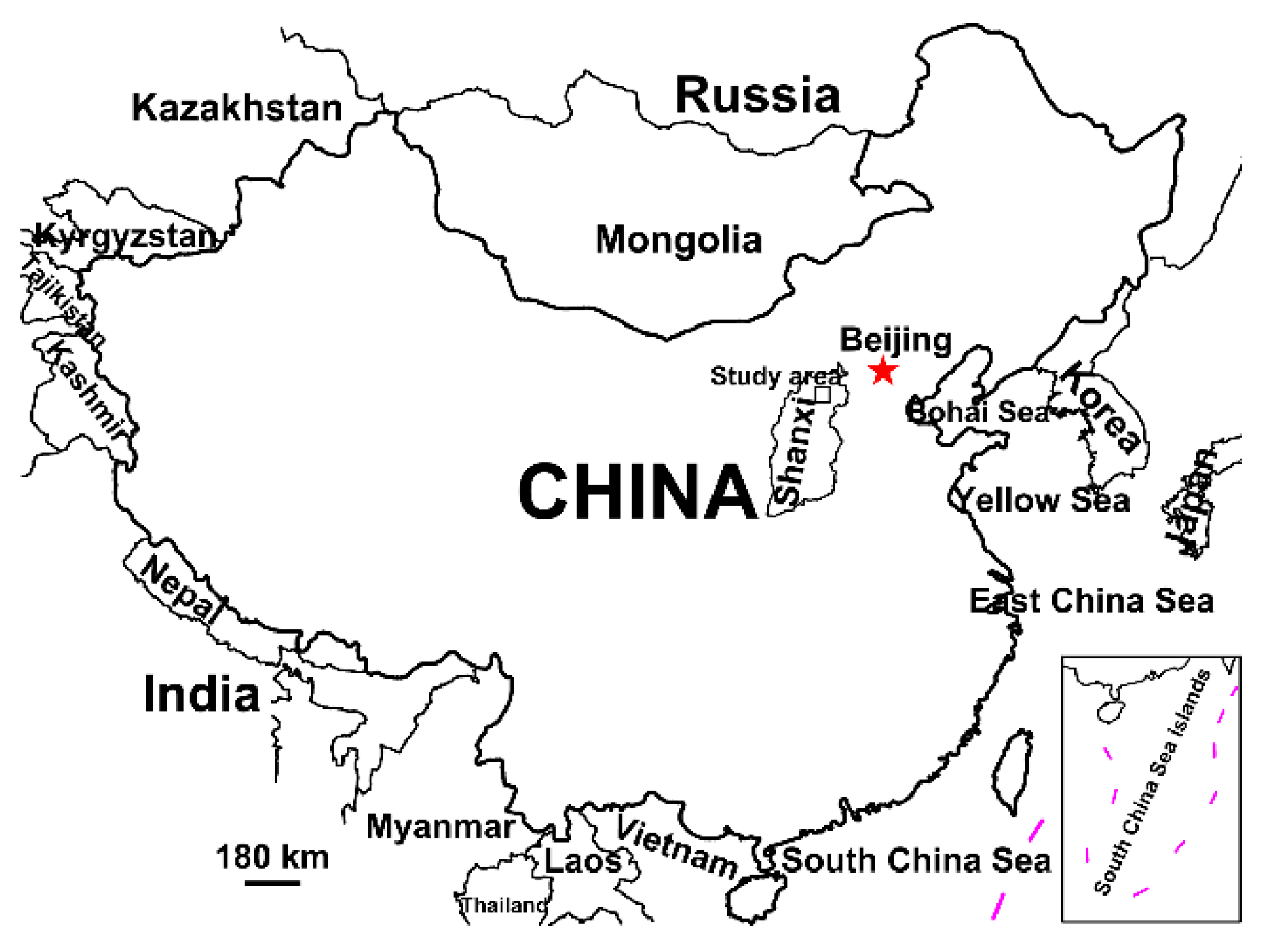
2.2. The Preparation of Simulated High Arsenic Groundwater

The simulated high arsenic groundwater in Datong basin, Northern China was used as the background media in this work. It was found that the concentrations of As(III) in Datong groundwater with pH value of 8.4 were ranging from 0 to 2.0 mg/L, mean ionic concentrations detected were shown in Table 1 with 161 high As groundwater samples collected from Datong basin (Figure 1) from Wu et al. [19]. The simulated high arsenic groundwater was prepared based on the maximum values of As concentration and the mean ion concentrations by adding 1.80 mg/L As(III) and other minerals (Table 2) in deionized water with pH 8.4.

2.3. Setup of Electrochemical Systems

The mixed and the anode-cathode separated electrolytic cells were set up and the separated system was formed with a salt bridge (Figure 2). Electrolytic tanks were maintained at 25 °C in water bath. Compared with other anode materials, Iron anode is usually used in the electrochemical treatment of pollutants in water since it is highly efficient, simple, cheap and environmentally-friendly. Thus, iron plates (5 cm length, 2.5 cm width and 0.3 mm thickness) were used as anode in the experiments. Plates were first polished with coarse emery cloth, etched by diluted HCl solution (5 wt.%), then washed ultrasonically with acetone, ethanol and deionized water. Graphite rods (0.52π × 5 cm3) were used as cathode. In the mixed electrolytic cell, the distance between anode and cathode was kept at 3.0 cm. For each trial, 500.0 mL simulated arsenic groundwater was transferred into the mixed electrolytic cell, and 250.0 mL simulated arsenic groundwater was added into anode and cathode tank respectively. The batch electrolysis experiments were carried out by applying 0.1, 0.2, 0.3, 0.4, 0.6 and 0.8 V supply voltages, respectively. The 0.1–0.8 V voltages was supplied by a GPC-6030D constant-voltage DC source (GWinstek, Suzhou, China) and referred to the potential difference between cathode and anode of the electrochemical cells. Water samples were taken out at the different electrolysis times and filtered through 0.22 μm PTFE filters, and pH values of the electrolyte were detected by a pH meter (Mettler Toledo, Zurich, Switzerland). Triplicate experiments were performed for each set.

3. Results and Discussion

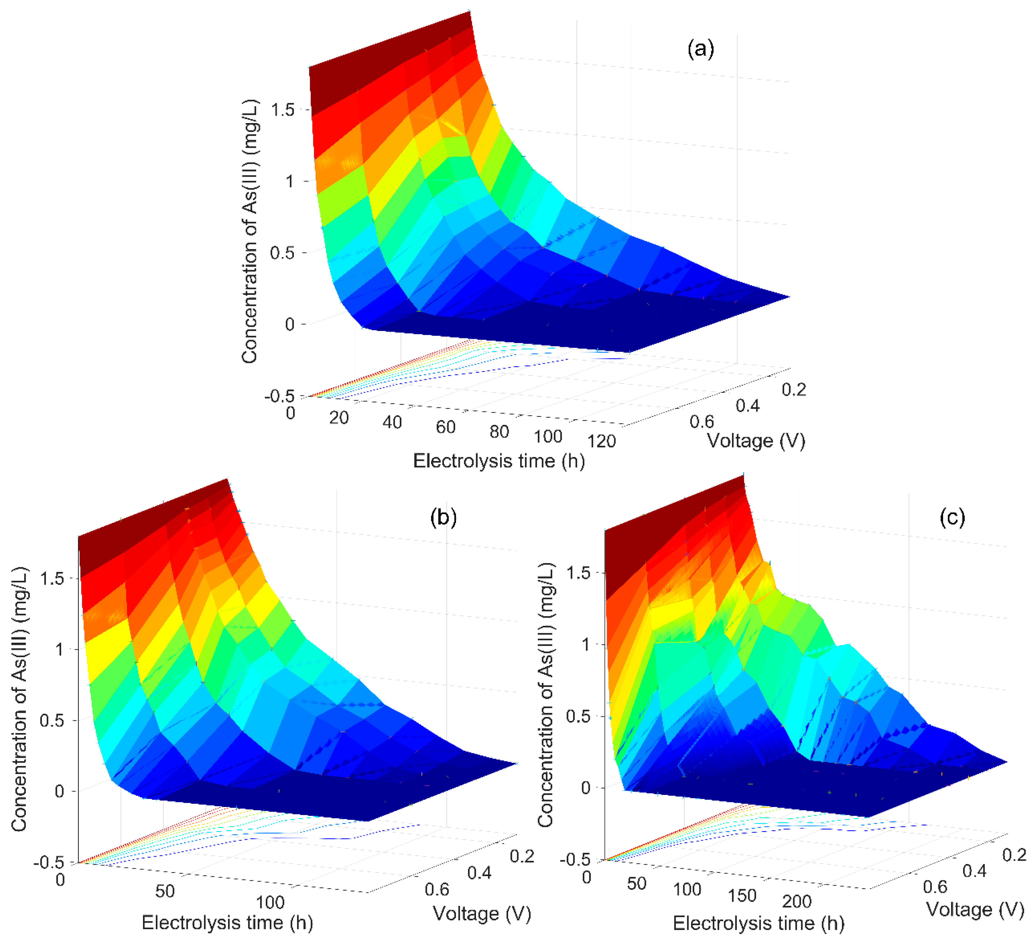
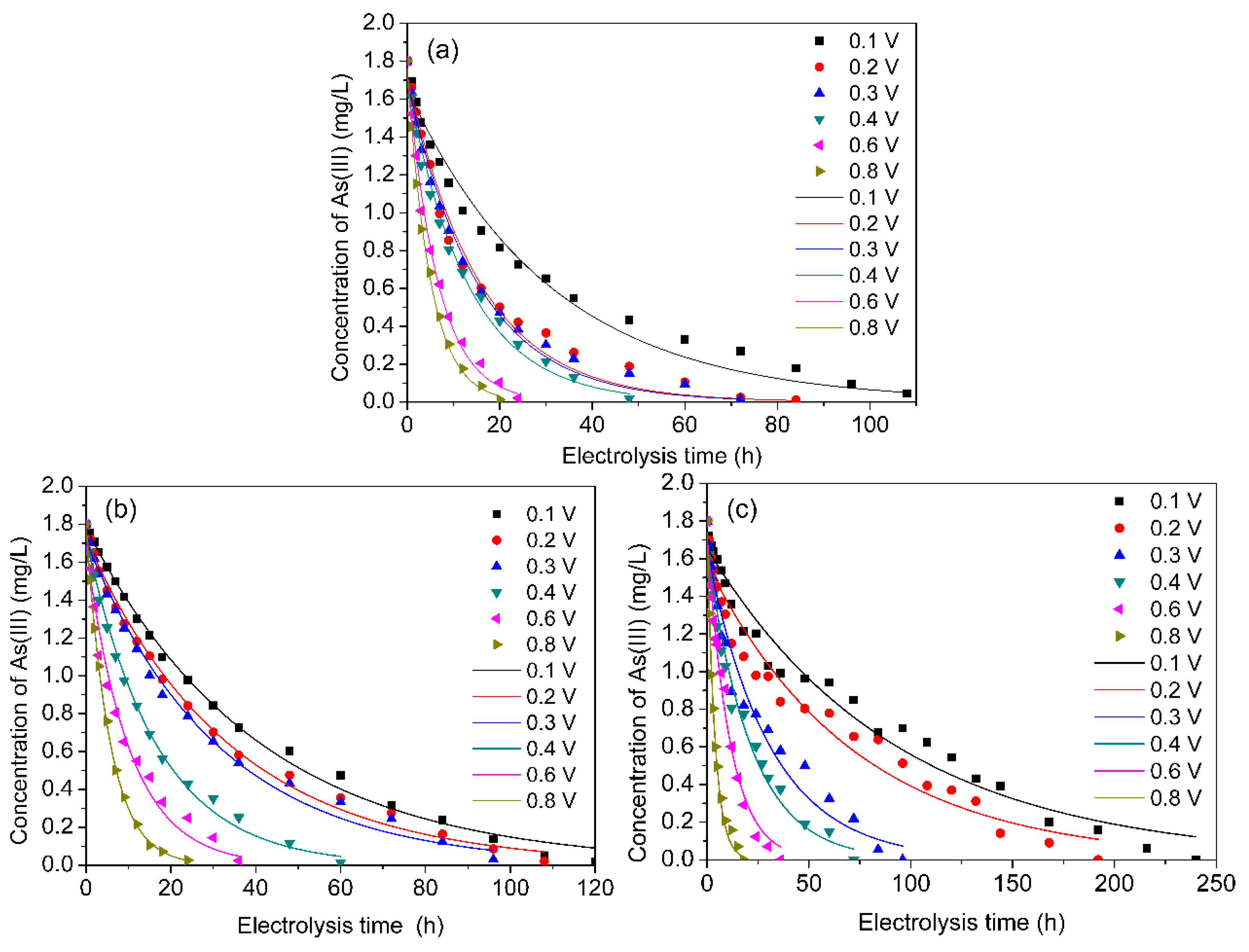
3.1. As(III) Concentration Changed with Electrolysis Time

Figure 3a,b show that the initial 1.8 mg/L As(III) in the mixed electrolytic cells and the anodic cells constantly decreased with electrolysis time as 0–0.8 V voltages were applied. As(III) could be oxidized to As(V) even at 0.1 V. The rate of As(III) oxidation and removal was increased with the rise of applied voltage. At 0.8 V, As(III) was completely removed in the mixed system at 20 h, and in anodic tank at 30 h; while, at 0.1 V, 120 h was needed for As (III) oxidation in mixed cell, and 132 h in anodic tank. With higher imposed voltage, the current was increased correspondingly. Based on Faraday’s law:   m = I × t × M Z × F   (where Z is the number of electrons transferred (eq/mol), M is the molecular weight (g/mol), and F is Faraday’s constant (96,485 coulombs/eq)), the generation of Fe2+ electro-oxidized by the iron anode (Equation (1)) increased with the increasing current [20]. During the electrolytic process, the reddish-brown flocculent precipitate was produced in the mixed cell and the anodic cell. The quantity of precipitation increased as the electrolytic time went on, correspondingly the color turned deeper and deeper. At higher voltage, the floccule occurred earlier and the rate of the floccule generation was greater.
Fe2+ was oxidized into Fe3+ by dissolved oxygen accompanied by the generation of H2O2 (Equations (2) and (3)) [7]. Recent research results indicate that under neutral and weakly alkaline pH conditions the reaction of FeII(OH)+ (Pk1 = 9.51) with H2O2 might produce the intermediate FeIVO2+ (i.e., Fe (IV)) as an active oxidant (Equations (4)–(6)) [21].
The most direct evidence to produce Fe(IV) was provided by identification of active oxidants with sulfoxide as probe compounds [22]. It was speculated that As(III) was oxidized to As(V) by the oxidizing agents (Fe(IV)) (Equation (7)) [23].
Fe(s) → Fe2+ +2e E0 = −0.44 V vs. SHE
Fe2+ + O2 → Fe3+ + ·O2 E0(Fe2+/Fe3+) = +0.77 V vs. SHE k1 = 60 M−1s−1 (pH 7.5)
Fe2+ + O2 + 2H+ → Fe3+ + H2O2 k2 = 1.0 × 10⁷ M−1s−1
Fe2+ + H2O → FeII(OH)+ + H+ Pk1 = 9.51
FeII(OH)+ + H2O2 → (OH)Fe(H2O2)+
(OH)Fe(H2O2)+ → FeIVO2+ + H2O + OH
The oxidation reaction of As(III):
H3AsO3 + 2 FeIVO2+ → HAsO42− + 2Fe3+ + 2H+ E0(As(III)/As(V)) = + 0.559 V vs. SHE (pH = 0) E0(As(III)/As(V)) = + 0.146 V vs. SHE (pH = 7) (pKa2 = 6.76, pH > 6.76)
At 0.1–0.8 V, pH in mixed electrolytic cells rose slight from 8.4 to 8.8 with the electrolytic time, and pH rose slower at lower applied voltage (Figure 4a). A slight pH rise phenomenon was also noted in the research of Vik et al. [24]. Arienzo et al. [25] held that the release of OH- from the ligand exchange during the adsorption of As(V) onto hydrated ferric oxide caused the rise of pH. While in anodic compartment of separated system, pH declined from 8.4 to 7.0 with the electrolytic time, and the drop rate of pH decreased with the decline of imposed voltage (Figure 4b). pH in the anodic cell decreased because Fe3+ hydrolysis consumed hydrogen ions and As(III) was oxidized into As(V) along with the release of hydrogen ions. Around the anode in the mixed electrolytic cell and in the anodic compartment of the separated system, the generation of intermediate active species Fe(IV) predominated in the weakly alkaline environment, so As(III) was oxidized into As(V) by dominant Fe(IV).
The generated ferric hydroxide (Equations (8)–(10)) had low adsorption capacity for As(III), hence small part of As(III) in solution might be removed by ferric hydroxide [24]. The equilibrium reactions of Fe(III) (Equations (8)–(10)) were as follows [21]:
Fe3+ + H2O = FeIIIOH2+ + H+
FeIIIOH2+ + H2O = FeIII (OH)2+ + H+ pKa = 3.6
FeIII(OH)2+ + H2O = FeIII(OH)3(s) + H+ pKa = 7.9
It was interesting to find that As (III) was also continuously decreased in the cathodic cell of the separated system (Figure 3c). At 0.1 V voltage the As (III) concentration was reduced to 0.60 mg/L as the electrolytic time was 84 h; As (III) completely disappeared at 18 h under an applied voltage of 0.8 V. The results indicated that As (III) could be reduced in cathodic cell even at 0.1 V, and the decrease speed of As (III) increased with the rise of voltage imposed and declined with electrolysis time.

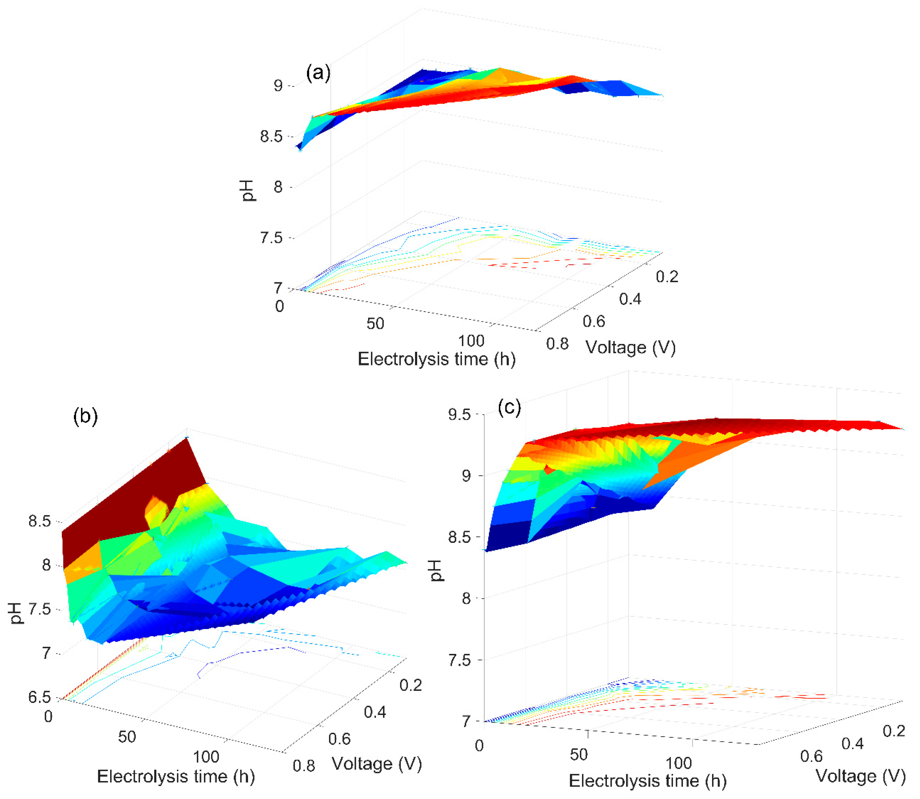
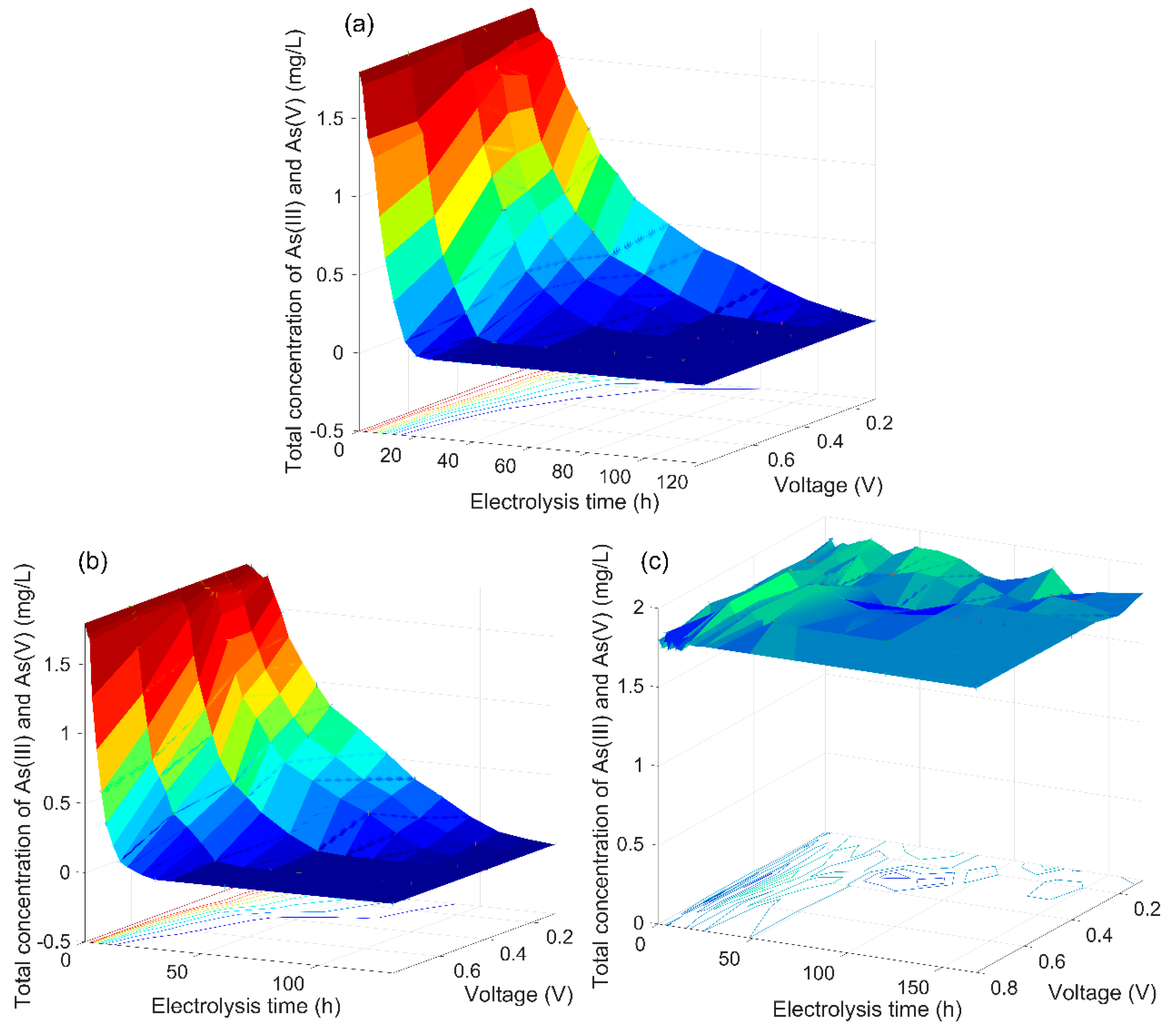
3.2. The Analysis of the As(V) Generation Process

In the mixed electrolysis system and the anodic cell of the divided system, As(V) was present in solution and increased very quickly to a maximum before 10 h (Figure 5a,b). At the beginning, the generation of As(V) was higher than the adsorption of As(V) by the generated hydrous ferric oxide, so the As(V) concentration increased; then, with less As(III) concentration, the As(V) generation speed was less than the As(V) adsorption speed, As(V) concentration decreased. The difference between the As(V) generation speed and the As(V) adsorption rate was expressed as the slope of As(V) concentration curve (Figure 5a,b). It was shown that As(V) generation and removal both increased as the applied voltage rose.
The current in the mixed system was greater than that in the separated system, and the rate of Fe(II) generation, the oxidation rate of As(III) and the rate of As(V) adsorption onto generated ferric hydroxide were greater than those in anodic cells of separate systems [24].
Under low voltage conditions, all the arsenic was removed effectively in both the mixed electrolytic system and the anodic cell of the divided system. The total arsenic concentration decreased with the increasing electrolytic time, and the rate of decrease of the total arsenic concentration became faster with the rise of voltage. The removal efficiency of total arsenic in the separated system was slightly slower than that in the mixed system (Figure 6a,b).
During the coagulation process, the arsenic removal rate rose with increasing production of ferric hydroxide [26]. According to Faraday’s law, the charge through the solution was proportional to the amount of dissolved iron [24]. This meant that the arsenic removal efficiency depended on the production amount of arsenic–hydrated ferric oxide compounds in the electrolysis process, namely it depended on the electric charge through the solution [10].
In the separated cathodic cell the As(V) concentration increased with the reaction time and the rise of voltage (Figure 5c), and the As(V) change trend was correspondingly opposite to that of As(III), and the total arsenic concentration remained unchanged (Figure 6c), which indicated that an efficient conversion of As(III) into As(V) also occurred in the cathodic cell of the divided system. Although, the As (III) transformation rate in the cathodic cell was a bit lower than that in the anodic cell of the divided system, it did not need to consume iron electrode and only power was needed to finish this transformation. As(III) pre-oxidation was completed in the cathodic cell of divided system which could be long-running with no consumption of electrode, low cost of operation and maintenance. It was speculated that there existed a reduction of O2 on the graphite used as cathode electrode. In theory, the reduction of oxygen to hydrogen peroxide is far more thermodynamically favorable than the four-electron reduction of water to hydrogen, thus reducing the energy costs for water detoxification. It is generally known that graphite is a potential cathodic catalyst material for in-situ generation of H2O2 by electrochemical reduction of O2, because of its large specific surface area, high conductivity, strong corrosion resistance, non-toxicity and low cost [27]. Leng et al. [28] found that more H2O2 was generated from oxygen reduction on the graphite cathode, compared with Pt, Ag and indium tin oxide glass, and the yield of H2O2 on the graphite cathode increased with ascending solution pH among the studied pH range from 2 to 12. The pH in the catholyte increased from 8.4 to 10 (Figure 4c), s, in this system, oxygen was reduced to hydrogen peroxide (H2O2) on graphite as cathode (Equation (11)):
O2 + 2H2O + 4e → 2H2O2 E0 = 0.695V vs. SHE
H3AsO3+H2O2 → HAsO42− + H2O+ 2H+ (pH > 6.76)
H2O2 might be converted to HO2, OH and O2 in basic electrolyte as follows (Equations (13) and (14)) [29]:
H2O2 + OH → H2O + HO2
H2O2 + HO2 →·OH + O2 + H2O
The oxidizing power of HO2, HO and O2 are stronger than H2O2. Consequently As(III) in catholyte was continuously oxidized to As(V). This was similar to the result of Luo et al. [17] where an alkaline medium was more favorable to the efficiency of phenol degradation than that in the acid medium on carbon black as cathode.
In both systems, the current decreased with the increase of electrolysis time. In the electrolysis process, a rough red brown oxide layer was formed gradually on the anode electrode, which led the resistance to increase [30]. The iron anode oxidation became more serious as the electrolysis time was extended at a higher applied voltage. The current in mixed electrolysis systems was always greater than the current in the separated systems, so correspondingly the output power in the mixed systems was greater than that in the separate systems, the reason might be that the salt bridge in the separated systems had an internal resistance which led to the resistance in the separate systems was higher than that in the mixed system. Power output in a microbial fuel cell (MFC) with a salt bridge or a membrane system was examined by Min et al. [31]. Power output in the MFC with a salt bridge (inoculated with G. metallireducens) was 2.2 mW m−2, power output in the MFC containing a proton exchange membrane was 40 ± 1 mW m−2 for G. metallireducens. The low power output was directly attributed to the higher internal resistance of the salt bridge system (19920 ± 50 Ω) compared with that of the membrane system (1286 ± 1 Ω) based on measurements using impedance spectroscopy.
In the electrolysis process, the conductivity in the two electrolytic systems increased from the original 2.5 ms/cm to 10–20 ms/cm; and the higher the applied voltage was, the greater the rise speed of the conductivity was. Charged ions including H+, OH- and Fe2+ was produced, and the neutral molecule H3AsO3 was transformed into charged HAsO42- in the electrolysis process, which caused the solution conductivity to go up. However, the whole resistance still increased continuously duo to the oxidation of the iron anode.

3.3. Kinetic Study of As(III) Transformation

The decrease of As(III) around the anode was mainly dependent on the As(III) oxidation by intermediate Fe(IV) species generated from the reaction between FeII(OH)+ and O2, at the same time, small part of As(III) was adsorbed by iron hydroxide [32]. The transformation kinetics of As(III) could be described using the apparent kinetic constant as follows [33,34]:
dC t dt = d [ As ( III ) ] oxidation dt + d [ As ( III ) ] adsorption dt = K obs 1 C Fe ( IV ) C t + K obs 2 C Fe ( OH ) 3 C t = K app C t
The decrease of As(III) around the cathode was mainly dependent on peroxides produced from 2e- reduction of O2 on the graphite cathode and the derived reactive oxygen species. The transformation kinetics of As(III) around cathode could be described using the apparent kinetic constant as follows (16) [35,36]:
dC t dt = K o bs C H 2 O 2 C t = K app C t
where Ct represented As(III) concentration (mg/L) at electrolytic time t, t represented electrolytic time (h), Kabs is the absolute rate constant of this reaction, and Kapp is the apparent rate constant of this reaction. Kapp directly reflected the change speed of As(III) concentration [37].
The Equations (15) and (16) can be integrated with the boundary conditions of t = 0 to t = t and Ct = C0 to Ct = Ct [38]:
ln C t C 0 = K app t
where C0 represents the initial As(III) concentration (mg/L).
Statistical analysis showed that at different voltages As(III) concentration change conformed to pseudo first-order kinetic equations (P < 0.0001) (Figure 7 and Table 3). The initial As(III) concentration in the simulated equation was from 1.6 to 2.0 mg/L (Table 1). The slope between -ln (Ct/C0) and electrolytic time was the reaction rate constant kobs, which increased with the rise of voltage due to that the generation speed of Fe2+ on iron anode increased with the rise of voltage.

3.4. Analysis of Energy Consumption

The function of instantaneous current (I) was integrated with electrolysis time to obtain the value of the electrolyte charge (Q) (Equation (18)) [39]. The energy consumption (E) was calculated by the following Equation (19) [39]:
Q = 0 t Id t
E = UQ
In the range of voltages studied, the energy consumption of the transformation of As (III) to As(V) at lower voltage was less than that at higher voltage (Table 4). Full transformation of As(III) to As(V) could be readily performed at a rather low voltage (Figure 3) and with less energy consumption (Table 4). The current decreased with the drop of voltage. The maximum efficiencies obtained in the oxidation of As(III) at low current densities was also reported in the two-compartment electrochemical cell with a dimensionally-stable anode (DSA) and a conductive-diamond anode (CDA) by Lacasa et al. [11], who also reported that oxygen evolution was not favored at lower voltage with lower current densities, and lower cell voltage lead to more efficient processes due to lower rates of water oxidation (Equation (20)) [11]. Although the rate of conversion of As(III) to As(V) was increased with the rise of applied voltage (Figure 3), the side reactions including oxygen evolution (Equation (20)) on anode, H2 evolution (Equation (21)) on the cathode, reduction (Equation (22)) and decomposition of hydrogen peroxide could be intensified by increasing the applied voltage or applied current [40]:
2H2O → O2 + 4H+ + 4e E0 = +1.23 V vs. SHE
2H2O + 4e → H2 + 2OH E0 = 0 V vs. SHE
H2O2+ 2H+ + 2e- → 2H2O E0 = +1.776 V vs. SHE
Low voltage electrolysis was of great significance to improve the treatment efficiency and reduce energy consumption.

4. Conclusions

The transformation from As(III) to As(V) in simulated high arsenic groundwater was performed under low voltage conditions in mixed electrolytic systems and anode-cathode separated electrolytic systems. When the applied voltages (the potential difference between cathode and anode) were 0.1, 0.2, 0.3, 0.4, 0.6 and 0.8 V, As (III) could be efficiently converted to As (V) in both mixed electrolytic cells and anodic compartments of divided electrolytic cells with iron as anode electrode. And total arsenic was effectively removed in mixed electrolytic cells and anodic cells of divided systems. Complete pre-oxidation of As(III) to As(V) also occurred in cathodic compartments of divided cells which could be long-running with no consumption of the graphite electrode. The change process of As(III) concentration in mixed electrolytic cells, anodic cells and cathodic cells all conformed to the pseudo first-order kinetics equation, C t = C 0   exp ( k app t ) . The conversion rate and removal rate of As (III) in mixed electrolytic cells were higher than those in the anodic cells of separated systems, for the reason of the high resistance of the salt bridge in the separated systems. Energy consumption analysis showed that the consumed energy of the As (III) conversion decreased as the voltage declined. Low voltage electrolysis is of great practical significance for reducing energy consumption and improving the current efficiency. These experimental results provide a theoretical reference for in-situ remediation of high arsenic groundwater using electrochemical method.

Author Contributions

Conceptualization, Y.L.; Formal analysis, Y.Q. and X.S.; Investigation, Y.Q., L.L., Y.G. and Z.Z.; Methodology, Y.C. and Y.L.; Supervision, Y.C.; Writing—Original Draft, Y.Q.; Writing—Review and Editing, Y.C.; Funding acquisition, Y.L. All authors have read and agreed to the published version of the manuscript.

Funding

This work was funded by “National Natural Science Foundation of China, grant number 41772262”, “the Fundamental Research Funds for the Central Universities, China University of Geosciences (Wuhan), grant number CUGL170209” and “China Postdoctoral Science Foundation, grant number 2018M642864”.

Acknowledgments

We are grateful to our research team who have participated in the study.

Conflicts of Interest

The authors declare no conflict of interest. The founding sponsors had no role in the design of the study; in the collection, analyses, or interpretation of data; in the writing of the manuscript, and in the decision to publish the results.

References

  1. Mueller, B. Arsenic in groundwater in the southern lowlands of Nepal and its mitigation options: A review. Environ. Rev. 2017, 25, 296–305. [Google Scholar] [CrossRef] [Green Version]
  2. Spaziani, F.; Natori, Y.; Kinase, Y.; Kawakami, T.; Tatenuma, K. Elementary iodine-doped activated carbon as an oxidizing agent for the treatment of arsenic-enriched drinking water. Water 2019, 11, 1778. [Google Scholar] [CrossRef] [Green Version]
  3. Lu, H.; Liu, S.; Zhang, H.; Qiu, Y.; Zhao, J.; Zhu, Z. Decontamination of arsenic in actual water samples by calcium containing layered double hydroxides from a convenient synthesis method. Water 2018, 10, 1150. [Google Scholar] [CrossRef] [Green Version]
  4. Back, J.; Stadlmayr, W.; Jabornig, S.; Winkler, F.; Winkler, K.; Rupprich, M. Removal of arsenic from water with non-thermal plasma (NTP), coagulation and membrane filtration. Water 2018, 10, 1385. [Google Scholar] [CrossRef] [Green Version]
  5. Hou, J.; Xiang, Y.; Zheng, D.; Li, Y.; Xue, S.; Wu, C.; Hartley, W.; Tan, W. Morphology-dependent enhancement of arsenite oxidation to arsenate on birnessite-type manganese oxide. Chem. Eng. J. 2017, 327, 235–243. [Google Scholar] [CrossRef]
  6. Zhang, P.; Tong, M.; Yuan, S.; Liao, P. Transformation and removal of arsenic in groundwater by sequential anodic oxidation and electrocoagulation. J. Contam. Hydrol. 2014, 164, 299–307. [Google Scholar] [CrossRef]
  7. Tong, M.; Yuan, S.; Zhang, P.; Liao, P.; Alshawabkeh, A.N.; Xie, X.; Wang, Y. Electrochemically induced oxidative precipitation of Fe(II) for As(III) oxidation and removal in synthetic groundwater. Environ. Sci. Technol. 2014, 48, 5145–5153. [Google Scholar] [CrossRef]
  8. Flores, O.J.; Nava, J.L.; Carreno, G.; Elorza, E.; Martinez, F. Arsenic removal from groundwater by electrocoagulation in a pre-pilot-scale continuous filter press reactor. Chem. Eng. Sci. 2013, 97, 1–6. [Google Scholar] [CrossRef]
  9. Maldonado-Reyes, A.; Montero-Ocampo, C.; Solorza-Feria, O. Remediation of drinking water contaminated with arsenic by the electro-removal process using different metal electrodes. J. Environ. Monit. 2017, 9, 1241. [Google Scholar] [CrossRef]
  10. Ratna Kumar, P.; Chaudhari, S.; Khilar, K.C.; Mahajan, S.P. Removal of arsenic from water by electrocoagulation. Chemosphere 2004, 55, 1245–1252. [Google Scholar] [CrossRef]
  11. Lacasa, E.; Canizares, P.; Rodrigo, M.A.; Fernandez, F.J. Electro-oxidation of As(III) with dimensionally-stable and conductive-diamond anodes. J. Hazard. Mater. 2012, 203, 22–28. [Google Scholar] [CrossRef]
  12. Kobya, M.; Gebologlu, U.; Ulu, F.; Oncel, S.; Demirbas, E. Removal of arsenic from drinking water by the electrocoagulation using Fe and Al electrodes. Electrochim. Acta 2011, 56, 5060–5070. [Google Scholar] [CrossRef]
  13. Parga, J.R.; Cocke, D.L.; Valenzuela, J.L.; Gomes, J.A.; Kesmez, M.; Irwin, G.; Moreno, H.; Weir, M. Arsenic removal via electrocoagulation from heavy metal contaminated groundwater in La Comarca Lagunera Mexico. J. Hazard. Mater. 2005, 124, 247–254. [Google Scholar] [CrossRef]
  14. Wan, W.; Pepping, T.J.; Banerji, T.; Chaudhari, S.; Giammar, D.E. Effects of water chemistry on arsenic removal from drinking water by electrocoagulation. Water Res. 2011, 45, 384–392. [Google Scholar] [CrossRef]
  15. Amrose, S.E.; Bandaru, S.R.S.; Delaire, C.; van Genuchten, C.M.; Dutta, A.; DebSarkar, A.; Orr, C.; Roy, J.; Das, A.; Gadgil, A.J. Electro-chemical arsenic remediation: Field trials in West Bengal. Environ. Int. 2009, 488–489, 539–546. [Google Scholar] [CrossRef]
  16. Hansen, H.K.; Nunez, P.; Jil, C. Removal of arsenic from wastewaters by airlift electrocoagulation. Part 2: Continuous reactor experiments. Sep. Sci. Technol. 2008, 43, 3663–3675. [Google Scholar] [CrossRef]
  17. Luo, H.; Li, C.; Wu, C.; Zheng, W.; Dong, X. Electrochemical degradation of phenol by in situ electro-generated and electro-activated hydrogen peroxide using an improved gas diffusion cathode. Electrochim. Acta 2015, 186, 486–493. [Google Scholar] [CrossRef]
  18. Lin, Y.; Yu, J.; Xing, Z.; Guo, X.; Yu, X.; Tang, B.; Zou, J. Enhanced generation of H2O2 and radicals on Co9S8/partly-graphitized carbon cathode for degradation of bio-refractory organic wastewater. Electrochim. Acta 2016, 213, 341–350. [Google Scholar] [CrossRef]
  19. Wu, Y.; Li, J.; Wang, Y.; Xie, X. Variations of uranium concentrations in a multi-aquifer system under the impact of surface water-groundwater interaction. J. Contam. Hydrol. 2018, 211, 65–76. [Google Scholar] [CrossRef]
  20. Lakshmanan, D.; Clifford, D.A.; Samanta, G. Ferrous and ferric ion generation during iron electrocoagulation. Environ. Sci. Technol. 2009, 43, 3853–3859. [Google Scholar] [CrossRef]
  21. Hug, S.J.; Leupin, O. Iron-catalyzed oxidation of arsenic(III) by oxygen and by hydrogen peroxide: pH-dependent formation of oxidants in the Fenton reaction. Environ. Sci. Technol. 2003, 37, 2734–2742. [Google Scholar] [CrossRef]
  22. Bataineh, H.; Oleg, P.; Andreja, B. pH-induced mechanistic changeover from hydroxyl radicals to iron(iv) in the Fenton reaction. Chem. Sci. 2012, 72, 1869–1878. [Google Scholar] [CrossRef]
  23. Pang, S.; Jiang, J.; Ma, J. Oxidation of sulfoxides and arsenic(III) in corrosion of nanoscale zero valent iron by oxygen: Evidence against ferryl ions (Fe(IV)) as active intermediates in Fenton reaction. Environ. Sci. Technol. 2011, 45, 307–312. [Google Scholar] [CrossRef]
  24. Vik, E.A.; Carlson, D.A.; Eikum, A.S.; Gjessing, E.T. Electrocoagulation of potable water. Water Res. 1984, 18, 1355–1360. [Google Scholar] [CrossRef]
  25. Arienzo, M.; Adamo, P.; Chiarenzelli, J.; Bianco, M.R.; De Martino, A. Retention of arsenic on hydrous ferric oxides generated by electrochemical peroxidation. Chemosphere 2002, 48, 1009–1018. [Google Scholar] [CrossRef]
  26. Edwards, M. Chemistry of arsenic removal during coagulation and Fe-Mn oxidation. J Am Water Works Assoc. 1994, 86, 64–78. [Google Scholar] [CrossRef]
  27. Li, N.; Wang, S.; An, J.; Feng, Y. Acid pretreatment of three-dimensional graphite cathodes enhances the hydrogen peroxide synthesis in bioelectrochemical systems. Sci. Total Environ. 2018, 630, 308–313. [Google Scholar] [CrossRef]
  28. Leng, W.H.; Zhu, W.C.; Ni, J.; Zhang, Z.; Zhang, J.Q.; Cao, C.N. Photoelectrocatalytic destruction of organics using TiO2 as photoanode with simultaneous production of H2O2 at the cathode. Appl. Catal. A Gen. 2006, 300, 24–35. [Google Scholar] [CrossRef]
  29. Wang, H.; Wang, J.L. The cooperative electrochemical oxidation of chlorophenols in anode–cathode compartments. J. Hazard. Mater. 2008, 154, 44–50. [Google Scholar] [CrossRef]
  30. Bensadok, K.; Benammar, S.; Lapicque, F.; Nezzal, G. Electrocoagulation of cutting oil emulsions using aluminium plate electrodes. J. Hazard. Mater. 2008, 152, 423–430. [Google Scholar] [CrossRef]
  31. Min, B.K.; Cheng, S.A.; Logan, B.E. Electricity generation using membrane and salt bridge microbial fuel cells. Water Res. 2005, 39, 1675–1686. [Google Scholar] [CrossRef] [PubMed]
  32. Li, L.; van Genuchten, C.M.; Addy, S.E.A.; Yao, J.; Gao, N.; Gadgil, A.J. Modeling As(III) oxidation and removal with iron electrocoagulation in groundwater. Environ. Sci. Technol. 2012, 46, 12038–12045. [Google Scholar] [CrossRef] [PubMed]
  33. Secula, M.S.; Cagnon, B.; de Oliveira, T.F.; Chedeville, O.; Fauduet, H. Removal of acid dye from aqueous solutions by electrocoagulation/GAC adsorption coupling: Kinetics and electrical operating costs. J. Taiwan Inst. Chem. Eng. 2012, 43, 767–775. [Google Scholar] [CrossRef]
  34. Maher, E.K.; O’Malley, K.N.; Heffron, J.; Huo, J.; Mayer, B.K.; Wang, Y.; McNamara, P.J. Analysis of operational parameters, reactor kinetics, and floc characterization for the removal of estrogens via electrocoagulation. Chemosphere 2019, 220, 1141–1149. [Google Scholar] [CrossRef]
  35. Zhang, X.; Lei, L.; Xia, B.; Zhang, Y.; Fu, J. Oxidization of carbon nanotubes through hydroxyl radical induced by pulsed O2 plasma and its application for O2 reduction in electro-Fenton. Electrochim. Acta 2009, 54, 2810–2817. [Google Scholar] [CrossRef]
  36. Gong, Y.; Li, J.; Zhang, Y.; Zhang, M.; Tian, X.; Wang, A. Partial degradation of levofloxacin for biodegradability improvement by electro-Fenton process using an activated carbon fiber felt cathode. J. Hazard. Mater. 2016, 304, 320–328. [Google Scholar] [CrossRef]
  37. Shafaei, A.; Rezaie, M.; Nikazar, M. Evaluation of Mn2+ and Co2+ removal by electrocoagulation: A case study. Chem. Eng. Process. Process Intensif. 2011, 50, 1115–1121. [Google Scholar] [CrossRef]
  38. Chen, X.; Ren, P.; Li, T.; Trembly, J.P.; Liu, X. Zinc removal from model wastewater by electrocoagulation: Processing, kinetics and mechanism. Chem. Eng. J. 2018, 349, 358–367. [Google Scholar] [CrossRef]
  39. Yu, F.; Chen, Y.; Pan, Y.; Yang, Y.; Ma, H. A cost-effective production of hydrogen peroxide via improved mass transfer of oxygen for electro-Fenton process using the vertical flow reactor. Sep. Purif. Technol. 2020, 241, 116695. [Google Scholar] [CrossRef]
  40. Ghalebizade, M.; Ayati, B. Acid Orange 7 treatment and fate by electro-peroxone process using novel electrode arrangement. Chemosphere 2019, 235, 1007–1014. [Google Scholar] [CrossRef]
Figure 1. Locations of the multi-level monitoring well site in Datong basin, China [19].
Water 12 01126 g001
Figure 2. Setup of electrochemical system (a) Mixed electrolytic cells; (b) Anode-cathode separated electrolytic cells (1. constant-voltage DC source; 2. electrolytic cells; 3. Sampling hole 4. salt bridge; 5. iron electrodes; 6. graphite rods).
Water 12 01126 g002
Figure 3. As(III) concentration at different electrolysis time in mixed electrolytic cells (a), anodic cells (b) and cathodic cells (c) of divided electrolytic systems, with 1.8 mg/L initial As(III) and applied voltages of 0.1, 0.2, 0.3, 0.4, 0.6 and 0.8 V.
Water 12 01126 g003
Figure 4. The pH change with the electrolytic time in mixed electrolytic cells (a), anodic cells (b) and cathodic cells (c) of divided electrolytic systems.
Water 12 01126 g004
Figure 5. The change of As(V) concentration with electrolysis time in mixed electrolytic cells (a), anodic cells (b) and cathodic cells (c) of divided electrolytic systems.
Water 12 01126 g005
Figure 6. The change of the total concentration of As(III) and As(V) in mixed electrolytic cells (a), anodic cells (b) and cathodic cells (c) of divided electrolytic systems.
Water 12 01126 g006
Figure 7. The conversion kinetics of As(III) in mixed electrolytic cells (a), anodic cells (b) and cathodic cells (c) of divided electrolytic systems.
Water 12 01126 g007
Table 1. Descriptive statistics of hydro chemical parameters of groundwater samples (n = 161) in Datong basin, Northern China.
Hydrochemical Parameters Min (mg/L)Median (mg/L)Mean (mg/L)Max (mg/L)
Cl41194327597
NO3<0.0517.3751900
SO42−<0.051293966951
HCO3464134871510
Ca2+4.642.560.8465
K+0.63.314.1370
Mg2+6.343.81011530
Na+7.81693353848
TDS172779165820576
Table 2. Preparation parameters of simulated high arsenic groundwater.
MgSO4NaHCO3NaNO3KClCaCl2FeCl2NaCl
Simulated groundwater (mmol/L)4.147.981.210.361.520.0548.65
Table 3. The parameters of the kinetic equations of As(III) conversion.
Voltage (V)The Mixed Electrolysis
System
The Anodic Cell of the Separated
System
The Cathodic Cell of the
Separated System
C0 (mg/L)KappR2C0 (mg/L)KappR2C0 (mg/L)KappR2
0.11.6150.0290.9801.8920.0280.9871.6040.0100.924
0.21.6440.0540.9791.8540.0330.9831.5160.0130.919
0.31.6140.0570.9851.7920.0340.9881.6170.0310.958
0.41.8350.0830.9761.9060.0680.9761.6580.0460.977
0.61.8920.1630.9861.7380.0980.9781.7150.0880.983
0.81.9810.2230.9761.7860.1791.0001.7350.2500.992
Table 4. The analysis of energy consumption.
Voltage (V)The Mixed SystemThe Separated System
Charge Quantity (C)Work (J)Unit Energy Consumption of As(III) Conversion (J/mg)Charge Quantity (C)Work (J)Unit Energy Consumption of As(III) Conversion (J/mg)
0.166.606.667.4088.568.869.84
0.289.2817.8619.84109.821.9624.40
0.393.0227.9131.0176.7023.0125.56
0.4119.1647.6652.9677.2030.8834.31
0.6136.4981.9091.0099.6159.7766.41
0.8141.10112.88125.42119.2395.39105.99

