The Design of a Vapor-Condensing Plume Abatement System and Devices for Mechanical Draft Cooling Towers
by
Xiaojing Zhu
1,2,†, 
Weihui Xu
3,4,†,
Weishu Wang
3,4,*,
Xu Shi
1,2,
Gang Chen
5 and
Shifei Zhao
3,4 1
Key Laboratory of Ocean Energy Utilization and Energy Conservation of Ministry of Education, Dalian University of Technology, Dalian 116024, China
2
Dalian University of Technology-Dalian Spindle Environmental Facilities Co., Ltd. Joint Research and Development Center, Dalian 116024, China
3
School of Electric Power, North China University of Water Resources and Electric Power, Zhengzhou 450045, China
4
Institute of Thermal Energy Engineering, North China University of Water Resources and Electric Power, Zhengzhou 450011, China
5
Shandong Lanxiang Environmental Technology Co., Ltd., Anqiu 262100, China
*
Author to whom correspondence should be addressed.
†
Co-first authors.
Water 2020, 12(4), 1013; https://doi.org/10.3390/w12041013
Submission received: 9 February 2020
/
Revised: 24 March 2020
/
Accepted: 24 March 2020
/
Published: 2 April 2020
(This article belongs to the Section Water, Agriculture and Aquaculture)
Abstract
:Cooling towers are widely used in many fields, but the generation of visible plumes has a serious impact on the environment. Moreover, the evaporation losses also cause a great waste of water. In this paper, a vapor-condensing plume abatement system was designed for a mechanical-draft cooling tower based on the mechanism of vapor plume generation. An effective method to achieve water-saving and eliminate the water fog generated in the cooling tower was proposed, and its feasibility was verified by using thermodynamic analysis. Next, the vapor-condensing plume abatement device was designed and used for both the confined space cooling tower (CSCT) and the free space cooling tower (FSCT). The surface type heat exchanger was adopted to design the vapor-condensing plume abatement device. Then a basic calculation flow and method were proposed to obtain thermodynamic operating parameters. According to the comparison between the results of theoretical calculation and practical engineering application, it was found that the designed vapor-condensing plume abatement system obviously benefits the water-saving of a mechanical-draft cooling tower and considerable economic benefits can be obtained. The contents presented provide the theoretical basis and technical support for the upgrade of the cooling tower and the design of the new cooling tower.
1. Introduction
Water resources are a key limiting factor of productivity in industrial manufacturing. Due to continued industrialization of China, industrial water-use now accounts for 25% of all its water-use, and water shortages have become a major constraint for industrial development. In particular, industrial cooling accounts for more than 80% of all industrial water-use [1]. Therefore, efforts to optimize cooling systems and processes, developing novel water-saving techniques, inventing key water-saving devices, and increasing the recovery of circulating water, are all important for reducing industrial water consumption.
Cooling towers are indispensable heat exchangers for industrial refrigeration, air-conditioning, and chemical engineering. In a cooling tower, heat exchange occurs between air and cooling water to cool the working fluid. During the operation of a cooling tower, large amounts of cooling water are lost to physical processes, including evaporation, drift, and blowdown [2]. Furthermore, the vapor produced by cooling towers has a substantial impact on both the immediate environment of the cooling tower and human health [3,4,5]. Researchers worldwide have conducted numerous studies on water-saving techniques and have examined theories to reduce blowdown, evaporation, and drift losses, in an effort to improve industrial water efficiency and reduce water loss in cooling towers. In particular, it has been shown that drift and blowdown losses can be mitigated by electrocoagulation, mechanical separation and capture, high cycles of concentration, and condensation [6]. Evaporation losses from a cooling tower are caused by the diffusion of cooling water into the air as water vapor, which then leaves the cooling tower in the form of hot-and-wet air. Evaporation losses account for a large percentage of cooling water losses, which are very difficult to recover.
Furthermore, these losses often lead to the formation of white vapor plumes that exit the tower and pollute the environment. To facilitate the recovery of evaporation losses from cooling towers, researchers have studied the mechanisms of evaporation loss from cooling towers, the causes of plume formation, and the factors that influence evaporation losses. In 1984, Thorp et al. [7] photographed the vapor plumes generated by cooling towers and derived the relationship between time and plume rise height. Bernier [8] performed theoretical and experimental analyses on the effects of fill height, water retention time, and air and water mass flow rates on cooling tower performance. Bornoff et al. [9] conducted a numerical study on the interactions between plumes produced by adjacent cooling towers, and they demonstrated that the interaction of adjacent plumes was dominated by the interaction of rotating vortex pairs within the plumes. Wang et al. [10,11,12] used heat pumps and solar collector heating systems to control visible plumes produced by the cooling towers of large commercial buildings. The results of these studies show that the generation of visible plumes by a cooling tower depends on external weather conditions, especially ambient temperature and relative humidity. Therefore, the use of heat pumps or solar collector heating systems to heat the air discharged by cooling towers will diminish or eliminate visible plumes. Xu et al. [13] evaluated the probability of plume generation by cooling towers in a typical subtropical region and discussed plume control and abatement strategies. Based on a sensitivity analysis of plume rise heights from cooling towers, Ding et al. [14] discovered that the primary determinant of plume rise height is the stability of the atmosphere around the cooling tower. Sánchez et al. [15] presented a numerical model capable of simulating the drift and evaporation of water droplets emitted by a mechanical cooling tower, which revealed the influence of external conditions on droplet lifetime.
With the development of computational fluid dynamics (CFD) technology, it has become an effective way of research and widely used in the prediction of a visible plume. Meroney [16] used CFD method to simulate the cooling tower plume dispersion and drift. Kazutaka et al. [17] employed CFD analysis to predict the scale of the visible plumes that rise from cooling towers, and they analyzed how the mixing of air from inside the cooling tower with external airflows affected the scale of the visible plume. In addition, they also investigated mechanisms that reduce the scale of these plumes. Marcia [18] developed a porous media thermosyphon technology for recovering vapor inside a cooling tower, which reduces water loss from cooling towers. This technology is capable of recovering approximately 10% of the water vapor that is lost to evaporation. Yang and Zhang [19] used CFD to simulate and analyze the transport and chemical transformation of power plant plumes. They divided plume evolution into two stages: a jet-dominated region (JDR) that is characterized by high levels of momentum in the plume, and an ambient-dominated region (ADR) that is driven by atmospheric boundary layer turbulence. Li et al. [20] formulated a novel analytical model of coaxial plumes, which can be used to control and abate cooling tower plumes. This model included a resistance factor, which is the ratio of the average non-dimensional velocity to the average relative humidity. The resistance factor can be used to characterize the likelihood of plume formation and/or the recirculation of moist air into the plume chamber.
From this brief review of the literature about cooling tower plumes, we conclude that most studies in this area have focused on the mechanisms that govern plume formation and diffusion, and the effects of vapor plumes on the environment. Currently, plume abatement is mainly conducted by heating moist air, which vaporizes the white, visible droplets in vapor plumes, thus “eliminating” the plume from sight. However, this approach does nothing to address the extremely high rates of evaporation losses that occur during the operation of a cooling tower, which is a necessary step for achieving industrial water saving targets. A tremendous number of mechanical draft cooling towers are currently operating in China, and the amount of water circulating in these towers exceeds 300 million m3/hour. The resulting evaporation losses are very large, and it is also very difficult to recover these losses. Accordingly, we present a method and system for condensing the water vapor of saturated hot-and-wet air through the use of recuperative heat exchangers, which enables the recovery of evaporation losses from mechanical draft cooling towers and the abatement of visible plumes. Based on a mechanistic analysis of condensate generation in cooling towers, we have designed a vapor-condensing plume abatement (VCPA) system for mechanical draft cooling towers, as well as VCPA devices for different types of cooling towers. The findings of this study will serve as a reference for the development of water-conserving plume abated cooling towers, and the augmentation of cooling towers that are currently in service with water-recovering plume abatement technologies.
2. The Mechanism of Vapor Plume Generation in Mechanical Draft Cooling Towers
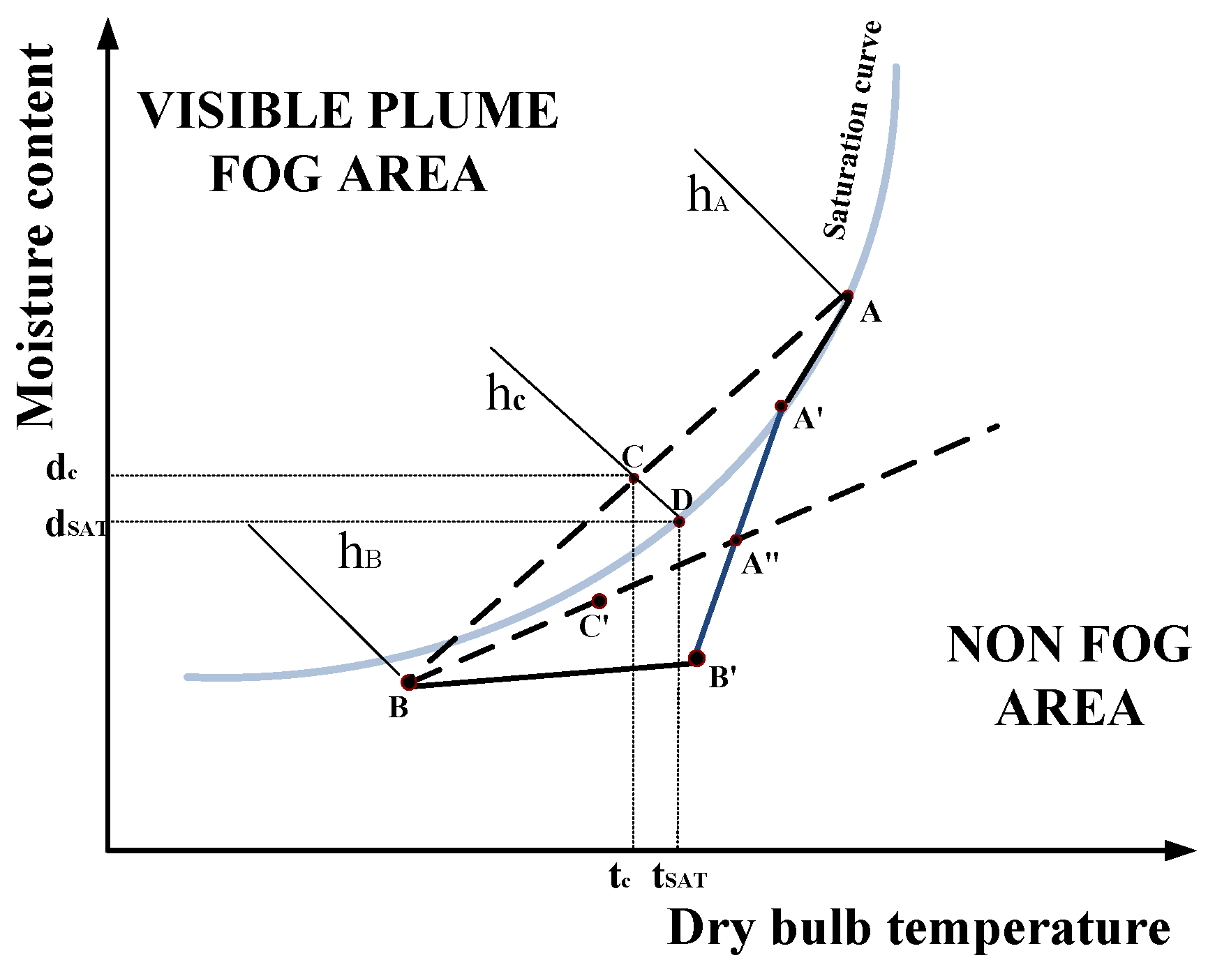
Humid air is formed by the mixing of air and water vapor, and air can become saturated with moisture at certain temperatures and pressures. As long as the humidity of a body of air is less than its saturation humidity, it will be able to absorb water, as it is still unsaturated. In unsaturated air, water exists as molecules that are invisible to the human eye. However, a decrease in temperature will decrease saturation humidity, which then increases relative humidity. If the relative humidity of the air is equal to 1, it is no longer able to absorb water and thus becomes supersaturated. Consequently, the water in the air becomes unstable, and the excess moisture in the air will condense into droplets; the suspension of these droplets in air leads to the formation of a vapor plume. In a conventional mechanical draft cooling tower, heat is removed from circulating water via evaporative cooling and the exchange of heat between air and water. The evaporated water vapor then enters the cooling tower to form hot-and-wet air, which changes into saturated hot air after passing through a water collector, and is then discharged from the tower by a fan. The airflows exiting the tower will mix with the air above and around the cooling tower, in a process that can be represented using a psychrometric chart, as shown in Figure 1. Term ‘A’ represents the state of airflows exiting the tower, ‘B’ is the state of the ambient air, and ‘C’ is the mixed state (mixture between airflows exiting the tower and ambient air). When the air discharged by the cooling tower mixes with ambient air, it gradually becomes similar to ambient air. Therefore, the psychrometric state of the mixed air varies along the AB segment; if the mixing ratio is 0, its state is A, and if the mixing ratio is ∞, its state is B. The intersection between AB and the isenthalpic line, hc, is C, a mixed state with humidity and temperature of dc and tc, respectively. If tc decreases to some value lower than tsat, the air is then supersaturated and has a relative humidity greater than 1. Consequently, the vapor in the air is unstable, and the humidity of the air will decrease from dc to dsat (along hc) by condensing into droplets, thus forming a visible plume.
3. Vapor-Condensing Plume Abatement System
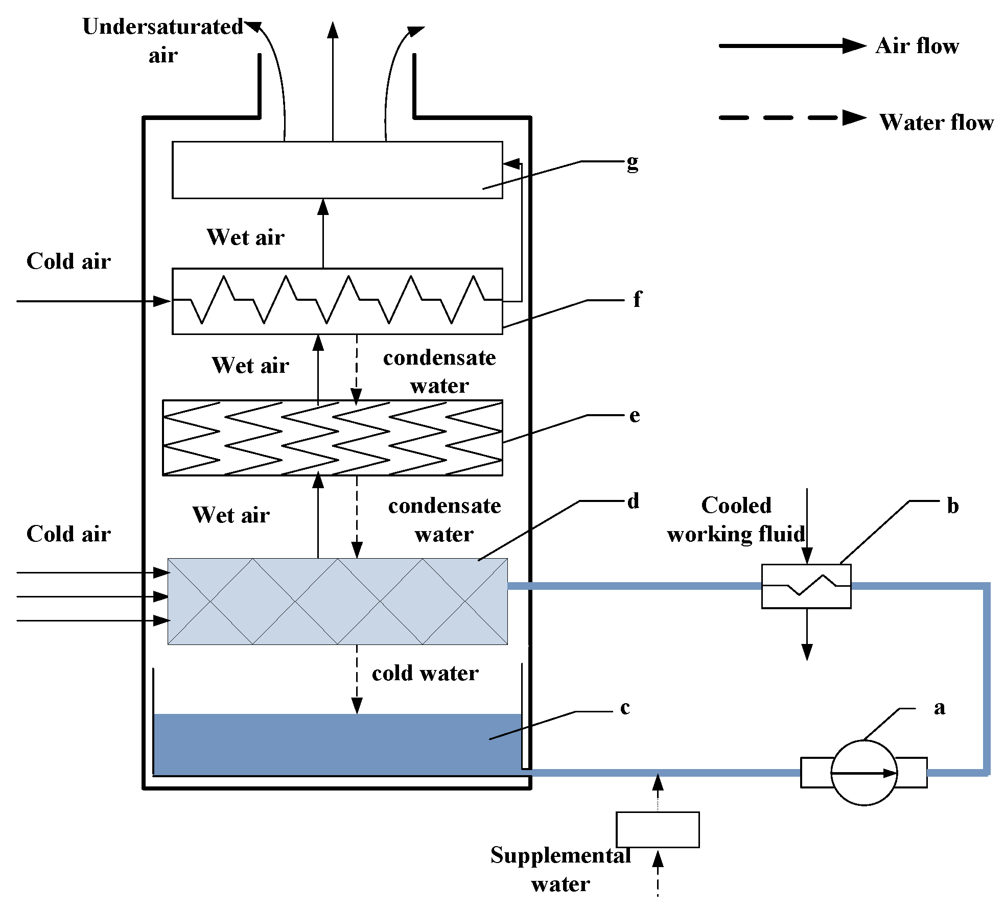
When air from the cooling tower mixes with ambient air, a vapor plume will not appear outside the cooling tower if the psychrometric state of the mixture does not pass through the visible plume zone and does not intersect the saturation curve. Ambient pressure, temperature, and humidity are important parameters, as they directly determine the psychrometric state of humid air. Ambient pressure depends on local climatic conditions; hence, it is not possible to utilize this parameter to recover evaporation losses and eliminate vapor plumes. Therefore, the only viable approach for avoiding plume generation is to reduce the temperature and humidity (i.e., psychrometric state) of airflows exiting the cooling tower. Heat exchangers are the most widely used type of device for reducing air temperature, and the addition of dry air is the fastest and most direct method for reducing humidity. In the designed VCPA system, heat exchangers and mixers have been added to the internals of a cooling tower (Figure 2). First, a circulating water pump (Figure 2a) pumps cooling water into a heat exchanger (Figure 2b), which is then cooled by the circulating fluid. The temperature of the circulating water increases as it removes heat from the heat exchanger. After the warm circulating water enters the cooling tower, it is sprayed over the fill by a set of sprinklers (Figure 2d). This decreases the temperature of the circulating water, due to convective heat transfer to cool air and evaporative cooling. After the circulating water has passed through the fill, it falls into a cold-water pool (Figure 2c), where it re-enters the circulation. As cool air passes through the fill, it absorbs a large amount of water and becomes hot, thus forming a stream of hot-and-wet air. The water collector (Figure 2e) then collects the water droplets in the supersaturated hot-and-wet air. The hot-and-wet air that has passed through the water collector is then cooled by a heat exchanger (Figure 2f), which condenses the water vapor in this air. The wet air exiting the heat exchanger then mixes with cool air in the mixing zone (Figure 2g) to form unsaturated air, which is then discharged from the cooling tower.
The VCPA system increases the amount of water vapor that is condensed in cooling towers, reduces evaporation losses, and eliminates the discharge of visible plumes. Therefore, our system provides an effective method for controlling plume generation. The working principles of the VCPA system are illustrated in Figure 2. By adding a new heat exchanger (Figure 2f), the hot-and-wet air is cooled by cool-and-dry air, thus altering the former’s psychrometric state from A to A’ (Figure 1). This increases the condensation of water vapor in the hot-and-wet air and increases the recovery of evaporation losses. After another round of heat exchange, cool air poised in the B’ state is then mixed with hot air in the A’ state, which further decreases the latter’s temperature and humidity from A’ to A’’. Finally, this air is discharged from the cooling tower. Unlike a conventional cooling tower, the airflows exiting a VCPA system are unsaturated, and the process by which the cooling tower’s outflows mix with ambient air proceeds along the A’’B segment instead of AB. Therefore, the psychometric state of the mixed air is C’, which is located in the region where a visible plume will not be formed. Hence, visible plumes will not be generated at the outlet of the cooling tower.
4. Vapor-Condensing Plume Abatement Devices
4.1. Design Ideas
Cooling towers can be divided into two classes: confined space cooling towers (CSCT) or free space cooling towers (FSCT), depending on whether the transition chamber (which is located above the water collector and below the narrowing air duct segment) is confined in space. CSCTs are cooling towers that are currently in service, which require modification, whereas FSCTs are newly constructed cooling towers. We have designed different condensing structures according to the characteristics of CSCTs and FSCTs, to facilitate efficient water recovery and plume abatement. The ideas that underlie our designs are as follows:
- (1)
- Effective condensing capabilities: A sufficiently large heat exchanging surface must be available so that adequate heat exchange may occur between hot and cold air.
- (2)
- Adequate mixing between hot and cold air: The cold and hot airflows that pass through the VCPA device should mix easily.
- (3)
- Modular design: A modular design makes it easy to swap heat exchangers and install the system. Modularity also improves the generalizability of the VCPA device and makes it easier to maintain and repair.
- (4)
- Effective water collecting functionality: The water collected by the condenser is valuable as it is clean and pure, and it should be collected by a water-collecting device. Therefore, the condenser should be an effective water collector.
- (5)
- Does not impede the cooling tower’s operations: The VCPA device must not hinder the ability of the cooling tower to cool circulating water, and it must allow the hot-and-wet air inside the cooling tower to flow normally.
4.2. Design Schemes
4.2.1. Vapor-Condensing Plume Abatement Device for CSCTs
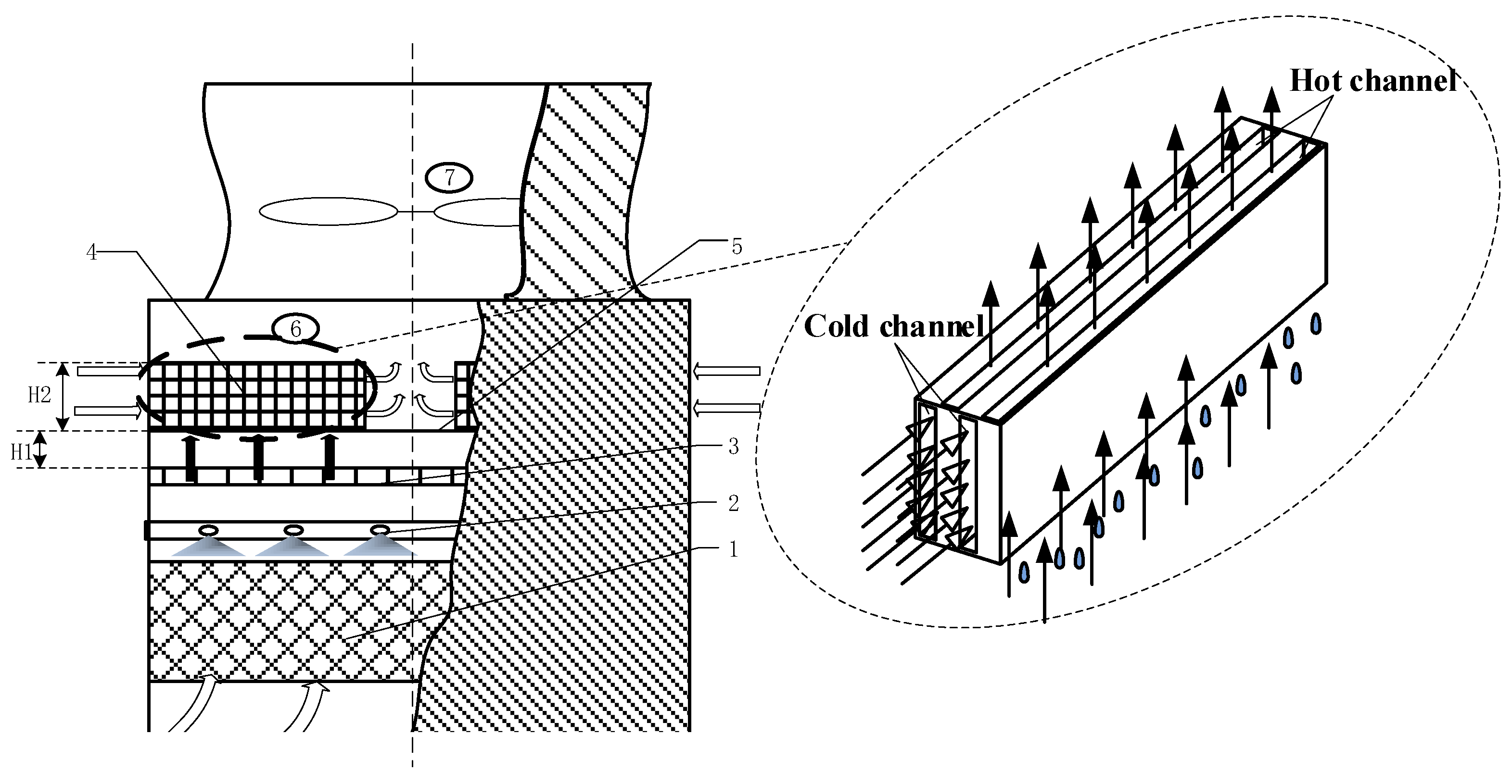
The modification of in-service CSCTs is performed by installing a VCPA device inside the CSCT. The height at which the condenser is installed must not be too high, or it will hinder airflow inside the cooling tower and reduce its efficiency. As shown in Figure 3, inlets for cool air have been installed on two sides of the cooling tower, above the water collector. The VCPA device in the CSCT consists of condensers and baffles. The baffles are installed below the middle area of the cooling tower, which can prevent the hot-and-wet air from reaching the transition chamber directly without passing through the condenser and help the hot-and-wet air and the cold air mix thoroughly. Due to height limitations in the transition chamber, the length of the section for hot-and-wet air to mix, H1, is usually 0.2 m, whereas the height of the condenser, H2, is usually 0.75 or 1 m, based on empirical experience.
The operation of a CSCT that has been equipped with a VCPA device is as follows: The sprinkler will spray circulating cooling water on the fill, which increases the area for heat exchange between the circulating water and cool air below the cooling tower. Then, due to evaporative cooling and heat exchange between cool air and the circulating water, the temperature of the circulating water decreases and cool air forms a stream of hot-and-wet air. Next, the cool-and-dry air that enters the cooling tower from its sides then undergoes heat exchange with hot-and-wet air within the condenser and gathers above the baffle in the middle of the cooling tower. The water collector will collect water droplets in this supersaturated hot-and-wet air. Then, in the transition chamber, this cool air mixes with hot-and-wet air that has passed through the condenser, and finally discharges from the cooling tower by the fan.
4.2.2. Vapor-Condensing Plume Abatement Device for FSCTs
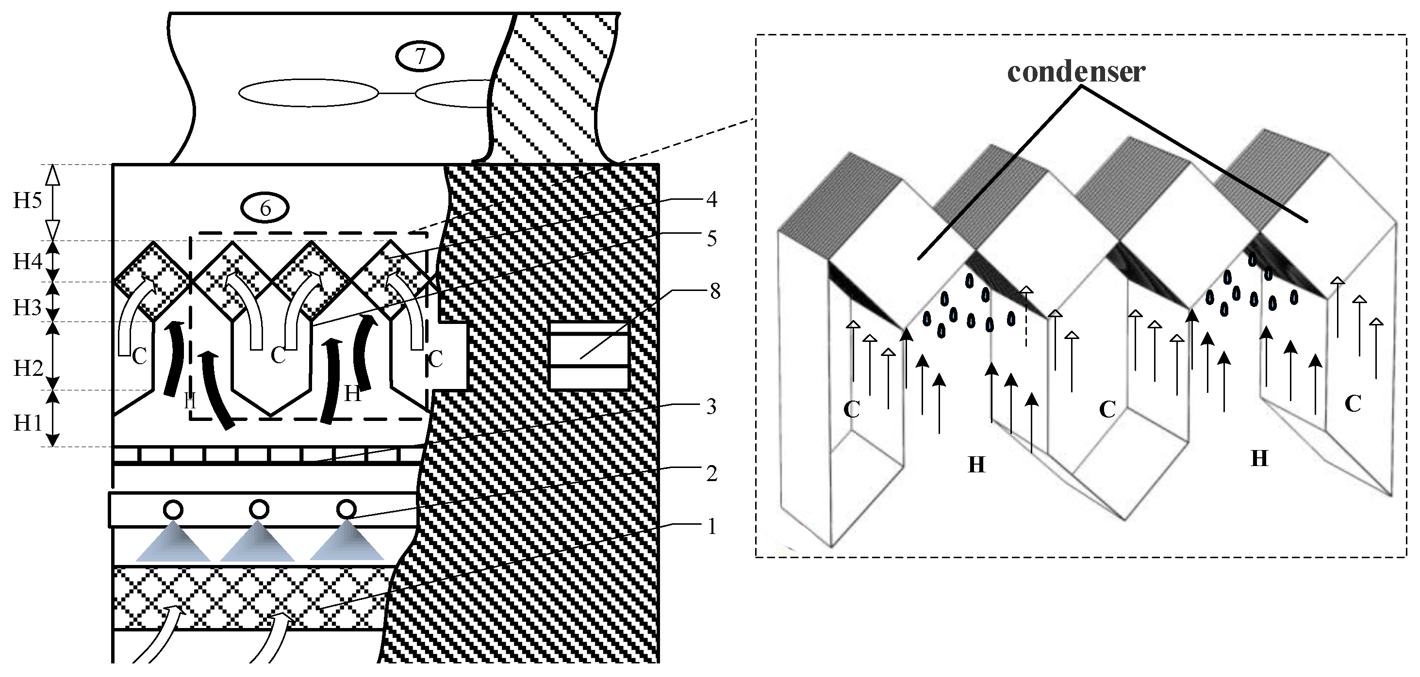
In newly constructed FSCTs, there are no height restrictions for the VCPA device. This advantage can be utilized to improve their efficiency. As shown in Figure 4, the VCPA device for FSCTs consists of cool-air channels (C), hot-air channels (H) and multiple rows of condensers. The cool-air channels have a triangular shape, and they also serve to guide the flow of hot-and-wet air. The condensers have a diamond-like arrangement, which makes it easier for hot and cold air to mix after heat exchange has occurred. To make it easier to repair and maintain the VCPA device, the height of the section where hot-and-wet air mix above the water collector, H1, is usually 1.5 m. The height of the cool-air inlet is H2, and its size depends on the area of the fill [21], such that:
where Stl is the area of the fill in m2.
The height of the cool-air channel’s walls is H3, and the formula for calculating H3 is:
In this equation, L is the length of the cooling tower, in m; v0 is the speed of cool air at the inlet, in m/s; Δp is the difference between the inlet pressure of the heat exchanger inside the cooling tower and the outlet pressure of the cool-air channel, in Pa; ρ is the density of the cool-and-dry air, in kg/m3; and H2 is the height of the cool-air inlet, in m.
The height of the condenser, H4, depends on the performance requirements of the heat exchanger.
The height of the transition chamber, H5, is given by the following formula [22]:
where Dfan is the diameter of the fan, in units of m.
The operation of a VCPA-equipped FSCT is as follows: The sprinkler will spray hot circulating water onto the fill to increase the surface area for heat exchange between the circulating water and cool air below the tower. In this way, the temperature of the circulating water is decreased by evaporative cooling and heat exchange with cool air. As cool air passes through the fill, its temperature and humidity will increase until it forms a stream of hot-and-wet air. The water collector then collects water droplets in the supersaturated air and causes it to revert to the saturated state. The hot saturated air will be guided by baffles below the cool-air channels into the hot-air channels, whereas the cool-and-dry air enters the cool-air channels via louvered inlets. Heat exchange then occurs between the air in the hot- and cool-air channels as they enter their respective channels in the condenser. The cool and hot air will then exit the condenser along the adjacent diamond-shaped cool- and hot-air channels and mix in the transition chamber, before being discharged into the atmosphere by a fan.
4.3. Design of the Condenser
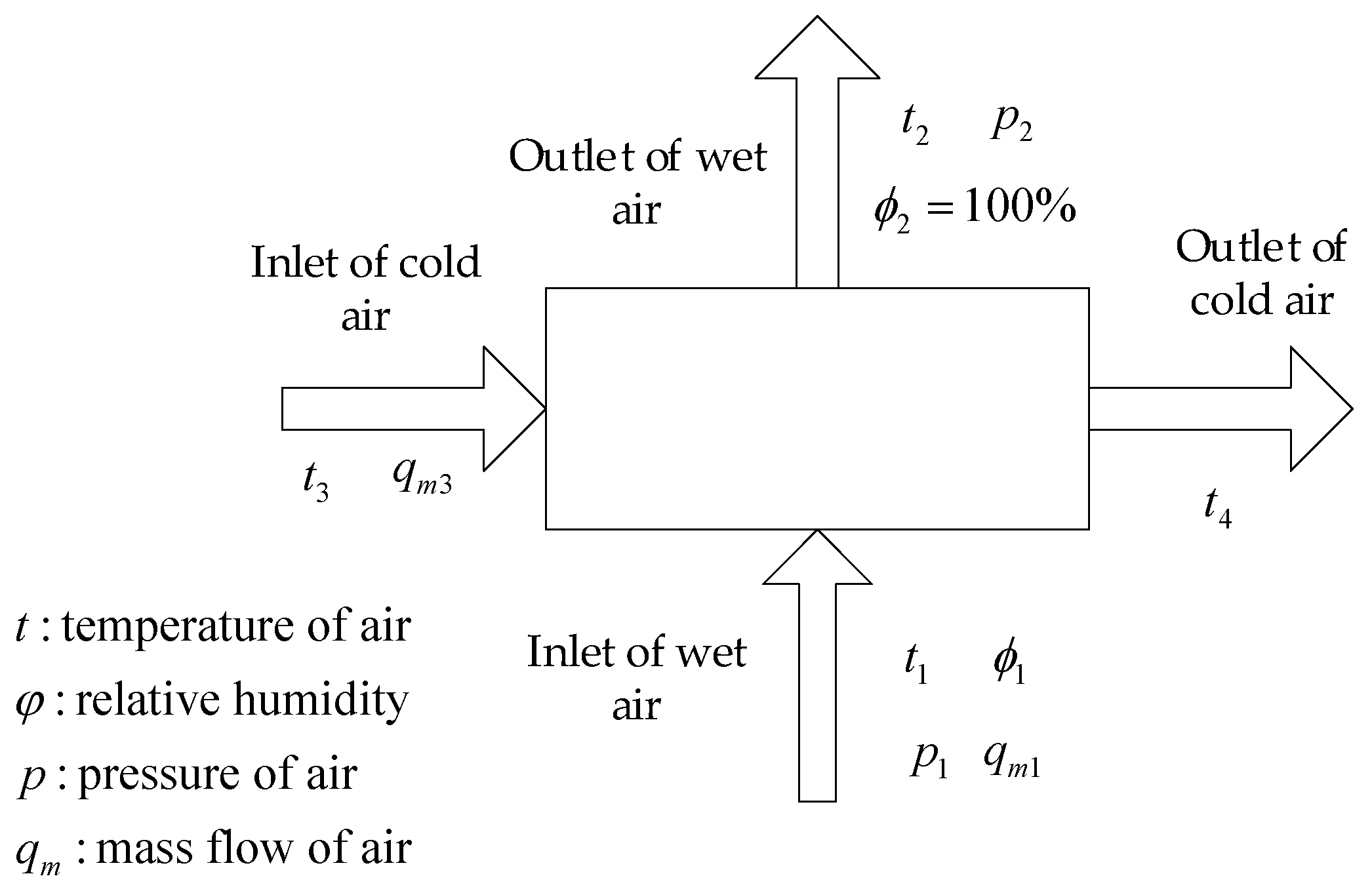
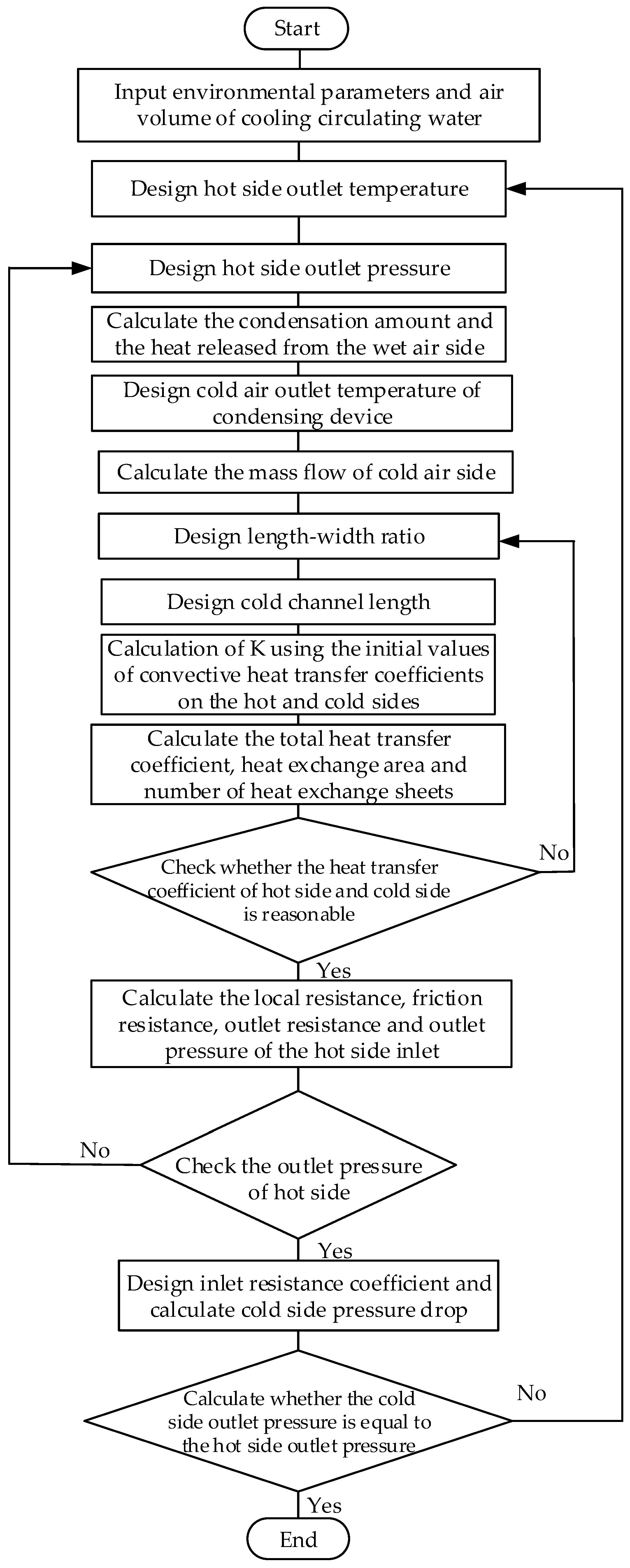
The purpose of designing the condenser is to obtain the appropriate outlet pressure and temperature of wet air, cold air flow, outlet temperature and pressure, and the heat exchange area of the whole condensing device. The relationship between design conditions and results are shown in Figure 5. Reasonable assumptions are made in the design and modeling: (1) stable and uniform water film is formed when the hot-and-wet air condenses; (2) radiative heat transfer is ignored; (3) the air on both sides is assumed to mix evenly in the channel; (4) Water film does not cause additional flow resistance. Based on the device structure model, the key mathematical model of device design is constructed.
A flow chart of the thermodynamic coupling calculation of the hybrid cooling tower is shown in Figure 6. The process mainly consists of the following three parts.
4.3.1. Mathematical Model of VCPA
(1) Working medium parameters
① Humidity ratio of air
where d is the humidity ratio of air, in kg/kg; pv is the pressure of water vapor, in Pa; pa is the pressure of dry air, in Pa; and p is the total pressure, in Pa.
② Enthalpy of air
where h is the enthalpy of air, in kJ/kg; and t is the temperature of air, in K.
③ The condensation rate of the condenser
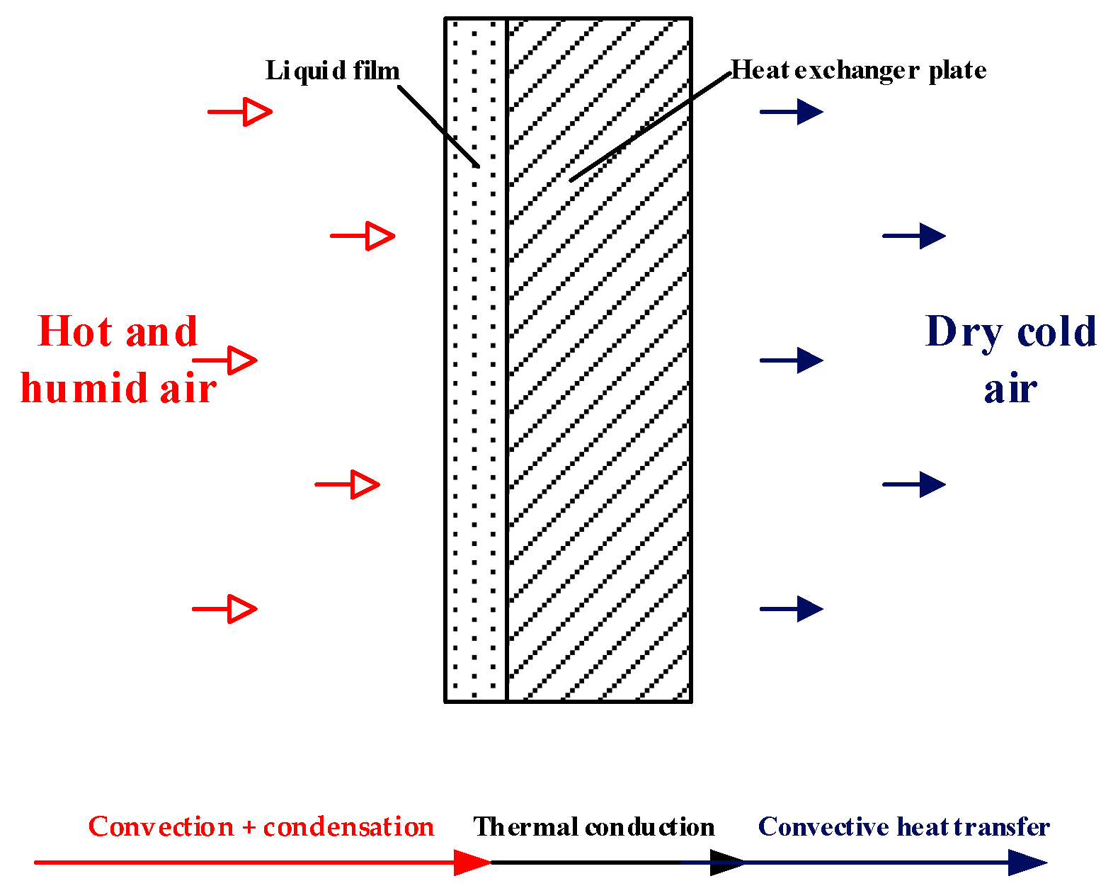
A schematic of the condenser we have designed for CSCTs and FSCTs is shown in Figure 7. First, heat is transferred from the hot-and-wet air inside the channel via convection and condensation to the walls of the hot-air channel. Heat is then transferred from the walls of the condenser to the walls of the cold-air channel on the other side. The cold air then removes heat via convective heat transfer. In this way, the condenser cools and condenses the hot-and-wet air. After heat exchange in the condenser, the hot and cool air will mix in the space above the condenser, which reduces the temperature and humidity of the hot air, thus causing its psychrometric state to diverge from the saturation curve. In this way, the condenser eliminates plume generation from the cooling tower. Based on the working principles of the VCPA device, the hot-and-cool-air channels have been laid out in a recovery arrangement, so that the hot-and-wet air and cool air will intersect perpendicularly or obliquely. Hence, the use of a recovering heat exchanger for the condenser facilitates heat exchange between hot and cool air, and also the condensation and collection of water vapor.
The condensation rate of the condenser is given by:
In this equation, qln is the condensation rate, in kg/s; G is the airflow entering the lower part of the cooling tower, in kg/s; d1 is the humidity of the hot-and-wet air when it enters the condenser, in kg/kg; and d2 is the humidity of the hot-and-wet air when it flows out of the condenser, in kg/kg.
(2) Momentum equation
For the fluid in the narrow cold and hot channel, the momentum equation is needed to solve the motion of the fluid system.
where is mass force, and is the surface force.
(3) Energy equation
① The energy change in unit time of hot-and-wet air can be described by the following equation:
where Qh is the energy change of hot-and-wet air, in kJ/s; mh is the mass flow of hot-and-wet air, in kg/s; h1 is the inlet enthalpy of hot-and-wet air, in kJ/kg; and h2 is the outlet enthalpy of hot mosit air, in kJ/kg.
② Heat transfer process of solid wall
where Q is the heat transfer, in kJ/s; K is the heat transfer coefficient, in W/(m2·s); th is the average temperature of hot-and-wet air; tc is the average temperature of dry air; and A is the heat transfer area, in m2.
③ Energy equation of dry air
where Qc is the energy change of dry air, in J/s; qm is the mass flow of dry air, in kg/s; CP,C is the specific heat capacity of dry air, in J/(kg·s); tc1 is the inlet temperature of dry air; and tc2 is the outlet temperature of dry air.
4.3.2. Evaluation Index of Heat Exchanger
Based on the existing evaluation methods and principles of evaluation indexes of heat exchangers, combined with the actual operation experience of cooling towers and the working characteristics of VCPA, the performance evaluation indicators are as follows:
1. Vapor recovery rate
where is vapor recovery rate, is condensation rate and is evaporation losses.
2. Water collection rate
where is water collection rate, and is maximum condensation rate, which represents the condensation rate when the condensation temperature is ambient temperature.
4.3.3. Structure of the Heat-Exchanging Channels
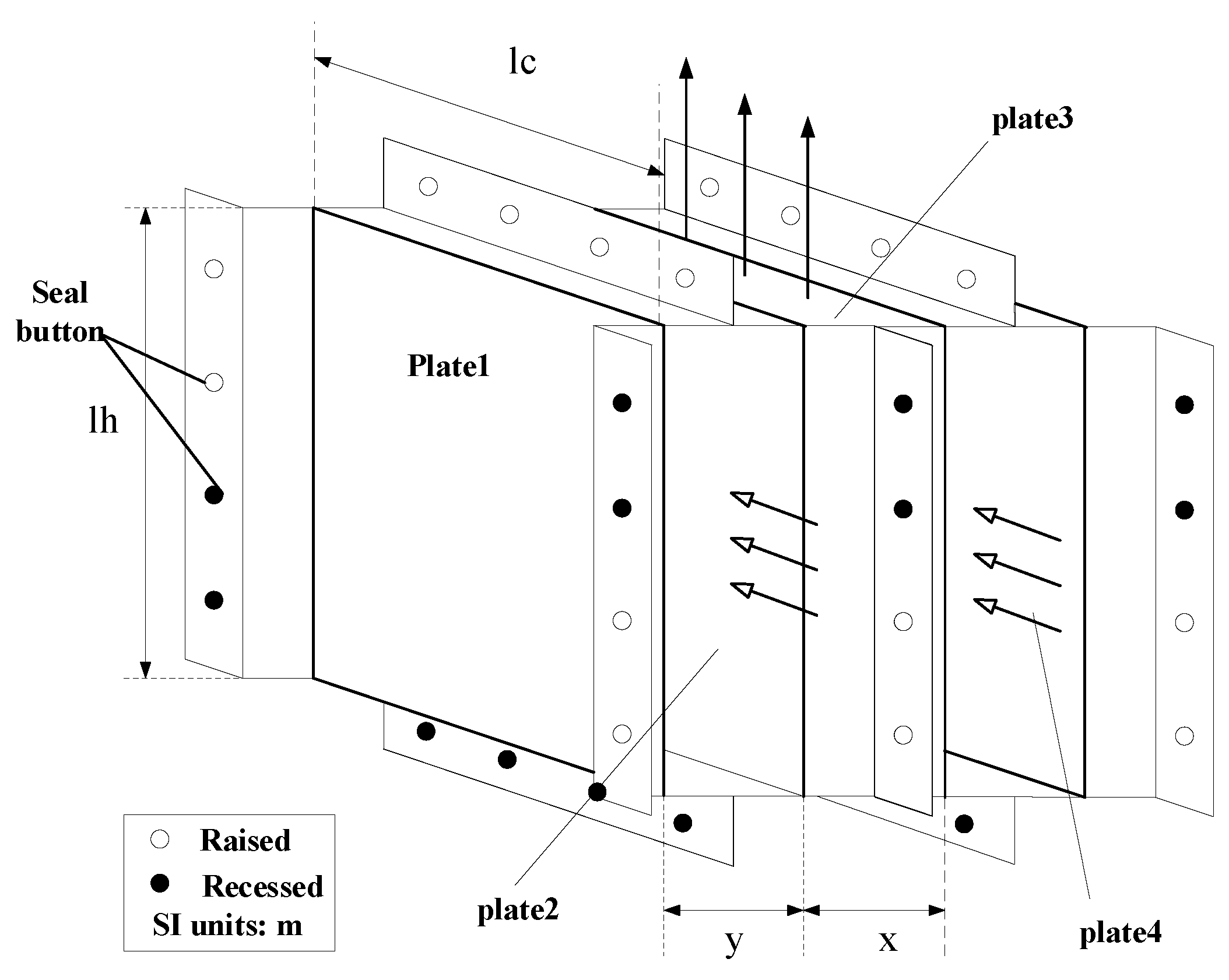
The CSCT and FSCT condensers both use recovery heat exchangers consisting of some arrangement of heat-exchanging components. Each heat-exchanging component is in turn made up of several cold and hot channels, laid out in an alternating arrangement. A schematic of the sealed channel structure we have designed is shown in Figure 8, where lh is the length of the hot channel, x is the width of each hot channel, lc is the length of the condenser’s cold channel, and y is the width of each cold channel. Hollow arrows indicate the flow of cold air, while solid arrows indicate the flow of hot air.
Each heat-exchanging channel consists of two heat-exchanging plates. Figure 8 illustrates a set of sealed cold/hot channels made from four heat-exchanging plates, and the heat-exchanging plates may either be flat or corrugated. Bonding points have been set up on the front and back of each heat-exchanging plate to seal the edges of the hot and cold channels. Each heat-exchanging plate has an L-shaped sealing plate at its edges, which has sealing buttons to seal the hot and cold channels. Stiffeners can also be installed around the seals to increase the overall strength of the heat-exchanging plates.
5. Results and Discussion
5.1. Design Example of CSCT and FSCT
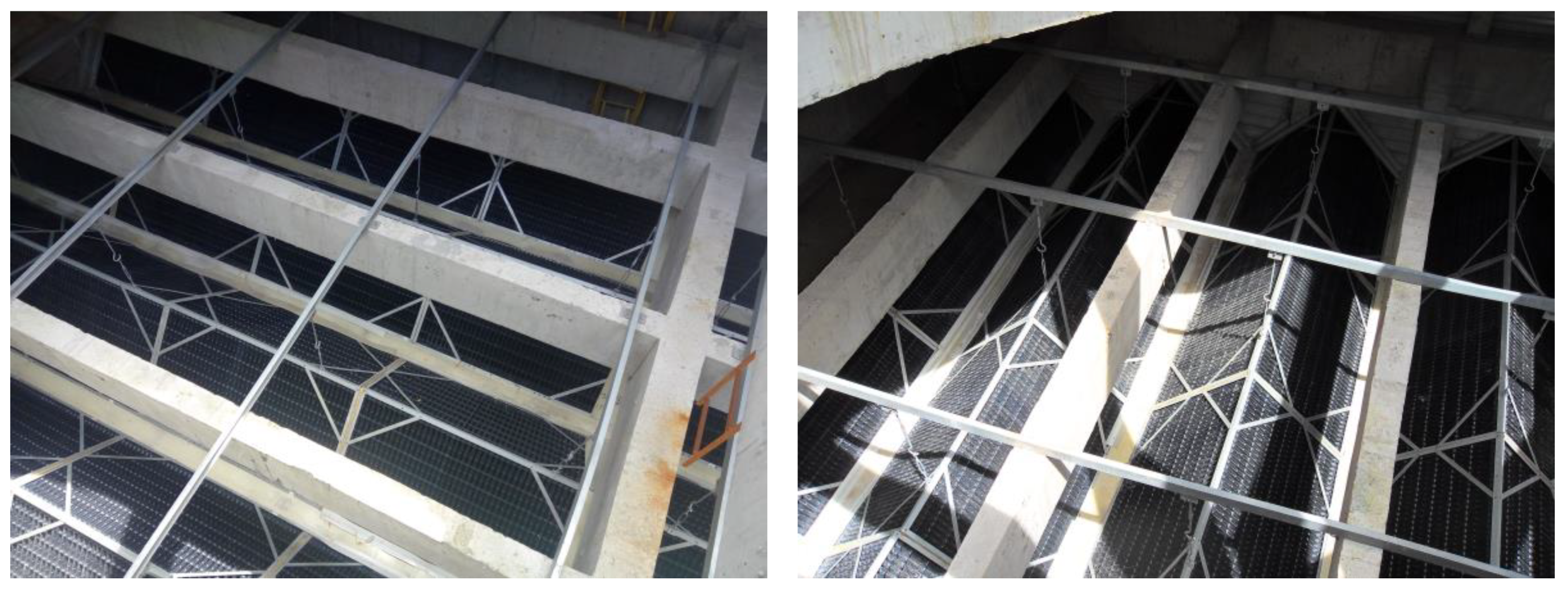
In this example, VCPA devices were designed for a factory that produces 300,000 tons of synthetic ammonia per annum, which requires 16,000 m3/hour of circulating water. Four fiberglass mechanical draft counterflow cooling towers have been installed at this factory, and each cooling tower cools 4000 m3/h of circulating water. The length and depth of each cooling tower are both 17 m, and the circulating water is refilled using urban tap water. These mechanical draft cooling towers were modified by installing CSCT-type VCPA devices and FSCT-type VCPA devices. The parameters of VCPA devices are shown in Table 1 and Table 2, and the spatial layout of VCPA devices in the cooling tower is shown in Figure 9.
Table 3 shows the operation parameters of the cooling tower, including atmospheric pressure (P), relative humidity (RH), dry bulb temperature (tdb), inlet temperature of cooling tower (tin), and outlet temperature of cooling tower (tout).
5.2. Results and Validity of Design Example
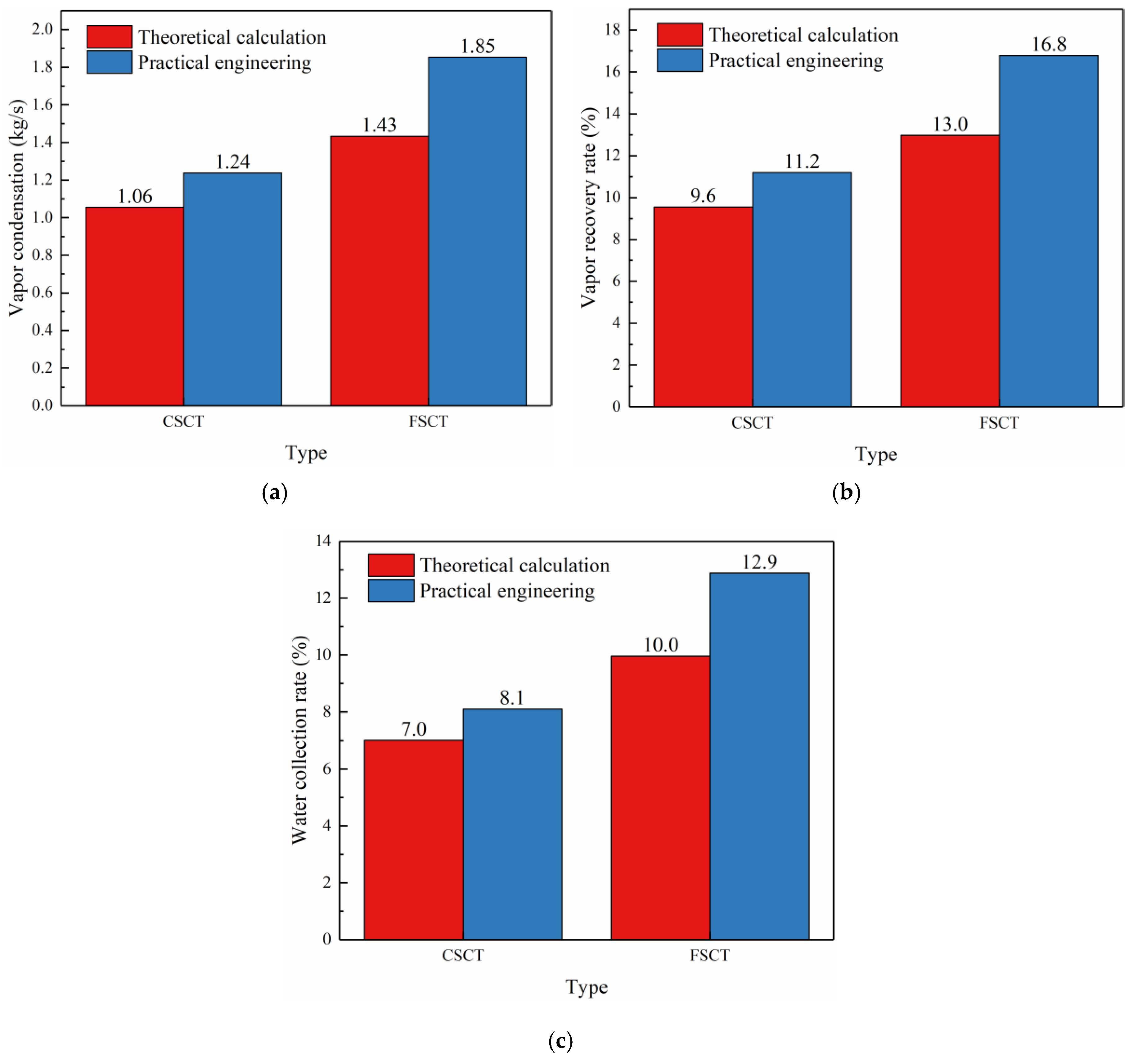
As mentioned in the above section, some performance parameters of the VCPA device such as vapor condensation, vapor recovery rate (recovered water as a percentage of evaporation losses) and water collection rate (recovered water as a percentage of the maximum amount of water that can be recovered) can be obtained.
Base on the mechanism of vapor plume generation and theoretical calculation model, we have carried out experimental research on the VCPA device and then put it into practical engineering application. The results show that the VCPA device has good performance of water conservation and plume abatement and it can also prove the feasibility of the theory and the guiding significance of theoretical calculation.
Table 4 and Table 5 show the specific parameters of theoretical calculation and practical engineering application of CSCT and FSCT.
Figure 10 compares the theoretical calculation and practical engineering results. It can be obviously seen that the effect of practical engineering application is better than the expected results of theoretical calculation. That is because under the practical application, the meteorological conditions are not immutable, and the parameters such as vapor condensation are greatly affected by the meteorological conditions. Thus, the three practical numerical values are larger than the theoretical ones.
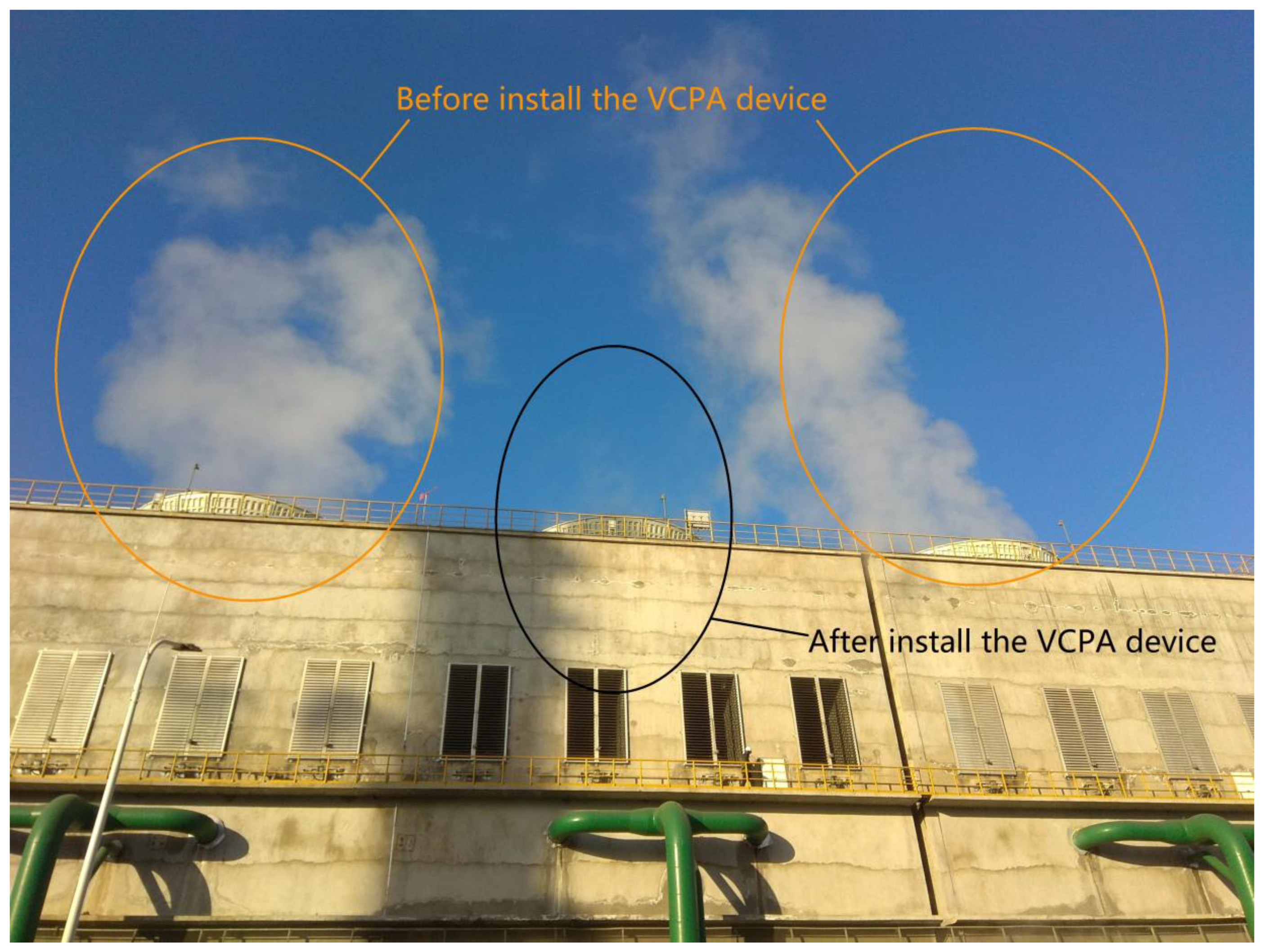
Figure 11 shows the effect of plume abatement before and after the installation of VCPA device in the cooling tower. It can be seen that after the installation of VCPA, the generation of plume has been reduced significantly.
5.3. Economic Analysis
Based on the practical engineering application of VCPA devices, the condensation rate of these devices in CSCT and FSCT are 1.24 kg/s and 1.85 kg/s, respectively. If a year of production corresponds to 7200 industrial hours and the cost of water is 6 CNY/m3, the water savings reaped by each VCPA device (in terms of monetary cost) are:
CSCT: 1.238 × 3.6 × 7200 × 6 = 192844.8 CNY/year.
FSCT: 1.85 × 3.6 × 7200 × 6 = 287712.0 CNY/year.
Therefore, the monetary value of the water saved by installing VCPA devices in four cooling towers could reach 771,000 CNY/year in CSCT and 1,151,000 CNY/year in FSCT, respectively. Furthermore, the elimination of “white smoke” pollution will also be beneficial for the general public.
6. Conclusions
The present study proposed an effective method to achieve water conservation and plume abatement, then the vapor-condensing plume abatement device was designed and used for both the confined space cooling tower (CSCT) and the free space cooling tower (FSCT). Based on the analytical investigation presented in this study, the following conclusions could be drawn:
- (1)
- Based on the analysis of the mechanism of vapor plume generation in mechanical draft cooling towers, a VCPA system has been designed for mechanical draft cooling towers. This forms a theoretical basis for the design of VCPA devices.
- (2)
- According to the specific characteristics of CSCT and FSCT, two different VCPA devices were designed respectively. Then a basic calculation flow and method were proposed to obtain thermodynamic operating parameters. According to the theoretical calculation, some performance parameters of VCPA such as water collection rate can be obtained.
- (3)
- The condensers in the VCPAs were designed with recovery heat exchangers, and a modular design was used for the condenser’s components. The heat-exchanging plates were coupled to each other to form the condenser’s cold and hot channels, which resulted in a structure that is both simple and cheap to construct. Furthermore, this structure readily enables the collection of water (from water vapor) without invoking the need for other coolants, and it does not affect the original cooling performance of the cooling tower.
- (4)
- Due to the influence of meteorological conditions, the effect of practical engineering application is better than that of theoretical calculation.
- (5)
- According to the comparison between the results of theoretical calculation and practical engineering application, it was demonstrated that the VCPA devices are capable of yielding considerable water-saving and societal benefits. The findings of this work will serve as a reference for the development of water-saving plume abated cooling towers and the augmentation of cooling towers that are currently in service with VCPA technology.
Author Contributions
Conceptualization, W.W.; methodology, W.W. and X.Z.; formal analysis, X.Z. and S.Z.; Resources, W.X. and G.C., writing—Original draft preparation, X.Z.; writing—Review and editing, W.X., X.S. and G.C.; supervision, W.W. and X.Z.; project administration, W.W. and W.X.; funding acquisition, W.W. and W.X. All authors have read and agreed to the published version of the manuscript.
Funding
This research was funded by the Science and Technology Innovation Team Support Plan of Henan Province (NO.16IRTSTHN017) and the Science and Technology Research Program of Henan Province (NO.172102310747).
Acknowledgments
The authors would like to thank the Institute of Thermal Energy Engineering of North China University of Water Resources and Electric Power and the data provided by Shandong Lanxiang Environmental Technology Co., Ltd.
Conflicts of Interest
The authors declare no conflict of interest.
References
- Wu, P.; Feng, H.; Niu, W.; Gao, J.; Jiang, D.; Wang, Y.; Fan, X.; Qi, P. Analysis of developmental tendency of water distribution and water-saving strategies. Trans. Chin. Soc. Agric. Eng. 2003, 19, 1–6. (In Chinese) [Google Scholar]
- Consuegro, A.J.; Kaiser, A.S.; Zamora, B.; Sánchez, F.; Lucas, M.; Hernández, M. Numerical modeling of the drift and deposition of droplets emitted by mechanical cooling towers on buildings and its experimental validation. Build. Environ. 2014, 78, 53–67. [Google Scholar] [CrossRef]
- Bentham, R.H.; Broadbent, C.R. A model autumn outbreaks of Legionnaries disease associate with cooling towers, linked to system operation and size. Epidemiol. Infect. 1993, 111, 287–295. [Google Scholar] [CrossRef] [PubMed] [Green Version]
- Isozumi, R.; Ito, Y.; Ito, I.; Osawa, M.; Hirai, T.; Takakura, S. An outbreak of Legionella pneumonia originating from a cooling tower. Scand J. Infect Dis. 2005, 37, 709–711. [Google Scholar] [CrossRef]
- Chang, T.; Lin, T. Water and energy conservation for a counterflow cooling tower using UV light disinfection and variable speed fan. Proc. Inst. Mech. Eng. Part E J. Process Mech. Eng. 2016, 230, 235–243. [Google Scholar] [CrossRef]
- Hafez, O.M.; Shoeib, M.A.; EI-Khateeb, M.A.; Abdel-Shafy, H.I.; Youssef, A.O. Removal of scale forming species from cooling tower blowdown water by electrocoagulation using different electrodes. Chem. Eng. Res. Des. 2018, 136, 347–357. [Google Scholar] [CrossRef]
- Thorp, J.M.; Orgill, M.M. Cooling tower visible plume rise analyses by time integrated photographs. Atmos. Environ. 1984, 18, 675–683. [Google Scholar] [CrossRef]
- Bernier, M.A. Cooling tower performance—Theory and experiments. ASHRAE Trans. 1994, 100, 114–121. [Google Scholar]
- Bornoff, R.B.; Mokhtarzadeh-Dehghan, M.R. A numerical study of interacting buoyant cooling-tower plumes. Atmos. Environ. 2001, 35, 589–598. [Google Scholar] [CrossRef]
- Wang, S.W.; Tyagi, S.K.; Sharma, A.; Kaushik, S.C. Application of solar collectors to control the visible plume from wet cooling towers of a commercial building in Hong Kong: A case study. Appl. Therm. Eng. 2007, 27, 1394–1404. [Google Scholar] [CrossRef]
- Tyagi, S.K.; Wang, S.W.; Ma, Z.J. Prediction, potential and control of plume from wet cooling tower of commercial buildings in Hong Kong: A case study. Int. J. Energy Res. 2007, 31, 778–795. [Google Scholar] [CrossRef]
- Wang, S.W.; Xu, X.H. Effects of alternative control strategies of water-evaporative cooling systems on energy efficiency and plume control: A case study. Build Environ. 2008, 43, 1973–1989. [Google Scholar] [CrossRef]
- Xu, X.H.; Wang, S.W.; Ma, Z.J. Evaluation of plume potential and plume abatement of evaporative cooling towers in a subtropical region. Appl. Therm. Eng. 2008, 28, 1471–1484. [Google Scholar] [CrossRef]
- Ding, F.; Xing, K.J.; Li, S.B.; Bai, J.H. Sensitivity analysis of plume rising height from cooling tower. Procedia Environ. Sci. 2010, 2, 1374–1379. [Google Scholar]
- Sánchez, F.; Kaiser, A.S.; Zamora, B.; Ruiz, J.; Lucas, M. Prediction of the lifetime of droplets emitted from mechanical cooling towers by numerical investigation. Int. J. Heat Mass Transf. 2015, 89, 1190–1206. [Google Scholar] [CrossRef] [Green Version]
- Meroney, R.N. CFD prediction of cooling tower drift. J. Wind Eng. Ind. Aerodyn. 2006, 94, 463–490. [Google Scholar] [CrossRef]
- Takata, K.; Michioka, T.; Kurose, R. Prediction of a visible plume from a dry and wet combined cooling tower and its mechanism of abatement. Atmosphere 2016, 7, 59. [Google Scholar] [CrossRef] [Green Version]
- Mantelli, M.H.B. Development of porous media thermosyphon technology for vapor recovering in cross-current cooling towers. Appl. Therm. Eng. 2016, 108, 398–413. [Google Scholar] [CrossRef]
- Yang, B.; Zhang, M. CFD-based turbulent reactive flow simulations of power plant plumes. Atmos. Environ. 2017, 150, 77–86. [Google Scholar] [CrossRef]
- Li, S.; Moradi, A.; Vickers, B.; Flynn, M.R. Cooling tower plume abatement using a coaxial plume structure. Int. J. Heat Mass Transf. 2018, 120, 178–193. [Google Scholar] [CrossRef]
- The Ministry of Housing and Urban-Rural Development of the People’s Republic of China; General Administration of Quality Supervision, Inspection and Quarantine of the People’s Republic of China. Code for Design of Cooling Tower for Mechanical Ventilation; China Planning Press: Beijing, China, 2016.
- Hu, L.; Wang, J.; Zhao, X. Analysis and design of the fluid state of the section of duct pervasion in the mechanical ventilation cooling tower. Ind. Water Treatment 2009, 29, 76–79. (In Chinese) [Google Scholar]
Figure 1.
Psychrometric chart of saturated air.

Figure 2.
Schematic of the vapor-condensing plume abatement system. (a) Water-circulating pump; (b) Heat exchanger; (c) Pool; (d) Fill; (e) Water collector (f) Heat exchanger; (g) Mixing zone.
Figure 2.
Schematic of the vapor-condensing plume abatement system. (a) Water-circulating pump; (b) Heat exchanger; (c) Pool; (d) Fill; (e) Water collector (f) Heat exchanger; (g) Mixing zone.

Figure 3.
Vapor-condensing plume abatement device for the confined space cooling towers (CSCTs). 1, Fill; 2, Sprinkler; 3, Water collector; 4, Condenser; 5, Baffle; 6, Transition chamber; 7, Fan.
Figure 3.
Vapor-condensing plume abatement device for the confined space cooling towers (CSCTs). 1, Fill; 2, Sprinkler; 3, Water collector; 4, Condenser; 5, Baffle; 6, Transition chamber; 7, Fan.

Figure 4.
Vapor-condensing plume abatement device for the free space cooling towers (FSCTs). 1, Fill; 2, Sprinkler; 3, Water collector; 4, Condenser; 5, Baffle; 6, Transition chamber; 7, Fan; 8, Louvered inlet.
Figure 4.
Vapor-condensing plume abatement device for the free space cooling towers (FSCTs). 1, Fill; 2, Sprinkler; 3, Water collector; 4, Condenser; 5, Baffle; 6, Transition chamber; 7, Fan; 8, Louvered inlet.

Figure 5.
Schematic diagram of calculation conditions of condenser.

Figure 6.
Calculation flow chart of condenser.

Figure 7.
Schematic diagram of the condensing unit.

Figure 8.
Schematic diagram of the sealed channel structure.

Figure 9.
The spatial layout of vapor-condensing plume abatement (VCPA) devices in the cooling tower.
Figure 9.
The spatial layout of vapor-condensing plume abatement (VCPA) devices in the cooling tower.

Figure 10.
Comparison between theoretical calculation and practical engineering. (a) Vapor condensation, (b) Vapor recovery rate, (c) Water collection.
Figure 10.
Comparison between theoretical calculation and practical engineering. (a) Vapor condensation, (b) Vapor recovery rate, (c) Water collection.

Figure 11.
Comparison of effect of plume abatement.


Table 1.
Design parameters of the confined space cooling tower (CSCT)-type vapor-condensing plume abatement (VCPA) device.
Table 1.
Design parameters of the confined space cooling tower (CSCT)-type vapor-condensing plume abatement (VCPA) device.
| Parameter | Unit | Value |
|---|---|---|
| Thermal conductivity of the heat-exchanging plate, λ | W/(m·k) | 0.17 |
| Plate thickness, δ | m | 4 × 10⁻⁴ |
| Length of hot channel, lh | m | 0.75 |
| Width of a hot channel, x | m | 0.026 |
| Length of each side of the cold channels, lc | m | 6.8 |
| Width of a cold channel, y | m | 0.049 |
| Total length of a cold channel | m | 15 |
| Number of heat-exchange fins in each element, N | - | 488 |
| Total heat exchanger surface area, A | m2 | 4758 |
Table 2.
Design parameters of the free space cooling tower (FSCT)-type VCPA device.
| Parameter | Unit | Value |
|---|---|---|
| Thermal conductivity of the heat-exchanging plate, λ | W/(m·k) | 0.17 |
| Plate thickness, δ | m | 4 × 10⁻⁴ |
| Length of hot channel, lh | m | 1.45 |
| Width of a hot channel, x | m | 0.051 |
| Length of cold channel, lc | m | 1.45 |
| Width of a cold channel, y | m | 0.017 |
| Number of heat exchanger unit | - | 8 |
| Number of heat-exchange fins in each element, N | - | 600 |
| Total heat exchanger surface area, A | m2 | 10,092 |
Table 3.
Operation parameters for cooling tower.
| Type | P (kPa) | RH (%) | tdb (°C) | tin (°C) | tout (°C) |
|---|---|---|---|---|---|
| CSCT | 101.02kPa | 47.8% | 8.4 | 38.0 | 28.0 |
| FSCT | 103kPa | 54.3% | 5.2 | 36.8 | 27.0 |
Table 4.
Calculated Parameters of the CSCT and FSCT.
| Parameter | CSCT | FSCT |
|---|---|---|
| Vapor condensation, kg/s | 1.06 | 1.43 |
| Vapor recovery rate, % | 9.6 | 13.0 |
| Water collection rate, % | 7.0 | 10.0 |
Table 5.
Practical engineering parameters of the CSCT and FSCT.
| Parameter | CSCT | FSCT |
|---|---|---|
| Vapor condensation, kg/s | 1.24 | 1.85 |
| Vapor recovery rate, % | 11.2 | 16.8 |
| Water collection rate, % | 8.1 | 12.9 |
© 2020 by the authors. Licensee MDPI, Basel, Switzerland. This article is an open access article distributed under the terms and conditions of the Creative Commons Attribution (CC BY) license (http://creativecommons.org/licenses/by/4.0/).
Share and Cite
MDPI and ACS Style
Zhu, X.; Xu, W.; Wang, W.; Shi, X.; Chen, G.; Zhao, S. The Design of a Vapor-Condensing Plume Abatement System and Devices for Mechanical Draft Cooling Towers. Water 2020, 12, 1013. https://doi.org/10.3390/w12041013
AMA Style
Zhu X, Xu W, Wang W, Shi X, Chen G, Zhao S. The Design of a Vapor-Condensing Plume Abatement System and Devices for Mechanical Draft Cooling Towers. Water. 2020; 12(4):1013. https://doi.org/10.3390/w12041013
Chicago/Turabian StyleZhu, Xiaojing, Weihui Xu, Weishu Wang, Xu Shi, Gang Chen, and Shifei Zhao. 2020. "The Design of a Vapor-Condensing Plume Abatement System and Devices for Mechanical Draft Cooling Towers" Water 12, no. 4: 1013. https://doi.org/10.3390/w12041013
Note that from the first issue of 2016, this journal uses article numbers instead of page numbers. See further details here.