Article

Anisotropic Spreading of Bubbles on Superaerophilic Straight Trajectories beneath a Slide in Water

1
Zhejiang Provincial Key Laboratory of Flow Measurement Technology, China Jiliang University, Hangzhou 310018, China
2
College of Control Science and Engineering, Zhejiang University, Hangzhou 310027, China
3
LEO Group Co., Ltd., Wenling 317500, China
4
Institute of Naval Architecture and Ocean Engineering, Ningbo University, Ningbo 315211, China
*
Author to whom correspondence should be addressed.
Water 2020, 12(3), 798; https://doi.org/10.3390/w12030798
Submission received: 10 February 2020 / Revised: 8 March 2020 / Accepted: 9 March 2020 / Published: 12 March 2020
(This article belongs to the Section Hydraulics and Hydrodynamics)

Abstract

:
Although the bubble contacting a uniformly superaerophilic surface has caused concern due to its application potential in various engineering equipment, such as mineral flotation, very little is known about the mechanism of how the bubble spreads on a surface with anisotropic superaerophilicity. To unveil this mystery, we experimentally studied the anisotropic behavior of a bubble (2 mm in diameter) spreading on the superaerophilic straight trajectories (SALTs) of different widths (0.5 mm–5 mm) in water using a high-speed shadowgraphy system. The 1–3 bounces mostly happened as the bubble approached the SALTs before its spreading. It is first observed that the bubble would be split into two highly symmetrical sub-bubbles with similar migration velocity in opposite directions during the anisotropic spreading. Two essential mechanisms are found to be responsible for the anisotropic spreading on the narrow SALTs (W ≤ 2 mm with two subregimes) and the wide SALTs (W ≥ 3 mm with four subregimes). Considering the combined effect of the surface tension effect of SALT and Laplace pressure, a novel model has been developed to predict the contact size r(t) as a function of time. The nice agreement between this model and our experiments reconfirms that the surface tension effect and Laplace pressure prevail over the hydrostatic pressure.

1. Introduction

Bubbles and drops spreading or attaching with the walls have been widely investigated and can be seen in nature and various industrial processes, such as diving bell spiders (Argyroneta Aquatica) [1], wastewater treatment, recovery of coal and minerals, and heat transfer [2,3]. For instance, the delay in the departure of air bubbles formed on the heater surface could impede the effectiveness transfer of heat with the surrounding medium [4]. Similarly, one of the greatest problems hindering the efficiency of the fuel cell is the adhesion of the electrochemically generated bubbles to the electrodes [5]. If the disturbed bubbles could be directionally transported to the designated areas or reduce the air film area, then the coverage area of the gas film can be significantly decreased after the bubble attachment, and the performance of the fuel cell and the heat transfer can be greatly enhanced. SALT proposed in this article seems to be a very promising method. Especially, due to being covered by a thin plastron of air, most of the superhydrophobic surfaces have remarkable super-aerophilic properties in the water and recently successfully been used in the directional and continuous transport of air bubbles in water [6,7]. In general, for the spreading of both bubbles and drops, the capillary length, surface tension, and gas/liquid density are three critical factors that play a very important role in interfacial hydrodynamics [8]. The balance among the friction, surface tension, and gravity has a significant effect on the bubble resistance motion [8,9].
As a millimetric bubble approaches a no-slip surface before spreading, it may repeatedly bounce on the surface [10]. The drainage of the liquid film [11,12] between the bubble and surface is the most crucial factor of rebounding behavior, as a result of bubble deformation and velocity. Tsao and Koch [13] found that the collision mechanism can be explained by the transition among the kinetic energy, surface energy, and potential energy. Pelletier and Béguin [14] experimentally investigated that, based on the restitution relations, the aspect ratio of a bouncing bubble before a rebound can be predicted after a rebound.
On the other hand, the contact of bubbles with different boundary walls present interesting phenomena, and many of them have broad potential in engineering applications. Compared to hydrophilic and hydrophobic surfaces, the bouncing probability of bubbles’ impact with aerophilic plates falls from 100% to 40% [15]. In addition, the rising bubble would slide on a hydrophobic wall, because the wall hydrophobicity thins the liquid layer between the wall and the bubble below its critical thickness and leads to the rupture of this liquid layer, and finally, a three-phase contact (TPC) is formed [16,17]. Wang et al. [18] observed the bubble bursting on lotus leaves and found that the height, width, and distribution of the hierarchical structures were responsible for the air bubble bursting on superhydrophobic surfaces, and the spreading time of bubbles is within milliseconds. De Maleprade and Clanet [15] experimentally studied the spreading of bubbles contacting the aerophilic surface and found that during the approaching and bouncing process, wall-effects affect the initial shape. The surface tension and later buoyancy are two crucial factors to drive the rapid evolution of bubbles spreading in three typical stages and further confirmed that the characteristic spreading time (10 ms) of the bubble on a superaerophilic surface (SALS) is much shorter than that in other plates, which agrees well with the results of Wang et al. [18]. Moreover, Ma et al. [19] combined the geometry-gradient structure with the spreading of bubbles on the upper SALS to manipulate the directional transport of bubbles without energy input.
As discussed above, previous research has been devoted to studying the dynamics of bubbles collision with surfaces [14], the directional and continuous transport of bubbles on superhydrophobic plates [19], or isotropic spreading on SALSs [15]; however, to our knowledge, no results aimed at the anisotropic spreading of bubbles on the SALSs have yet been reported. The anisotropic spreading of bubbles on the designated superaerophilic areas may motivate the novel technologies to enhance or reduce the reaction rate, mass, and heat transfer rate in some specific positions and then to improve the equipment performances in mineral flotation, selective aeration, bubble reactors, and so on. Here, we focus on bubbles’ anisotropic spreading on superaerophilic straight trajectories beneath a slide immersed in water. Concentrated efforts have led to understanding the effects of the width of the trajectories on bubble spreading for better prediction of bubble dynamic behavior as it is spreading. The SALT width can be regarded as an important characteristic parameter indicating the anisotropy of the spreading. Therefore, a bubble (2 mm in diameter) approaching and spreading on a series of width superaerophilic trajectories was investigated. The results will offer people ideas to manipulate bubbles in an aqueous environment.

2. Materials and Methods

2.1. Preparation for Superaerophilic Straight Trajectories (SALT)

The superaerophilic straight trajectories (SALT) are obtained using spray coating with a silica nanoparticle solution (Glaco, Soft99 Co., Japan, SiO2 of 30-nm primary diameter). After solvent evaporation, the coating is further dried in a vacuum drying chamber at 150 °C for 30 min, and this coating for a trajectory was repeated three times. Based on these procedures, silica particles can adhere to the trajectory surface, forming a superhydrophobic nanostructure with a typical roughness of about 100 nm, as reported by Maleprade et al. [15]. Other necessary operation steps for surface treatment are as follows: First, the glass surface is ultrasonically cleaned with ethanol solution for 5 min and then is rinsed with deionized water and is dried in the vacuum drying chamber. Second, the designated areas of trajectories are constructed using a mask to achieved different trajectory widths (0.5 mm–5 mm) on the slides. Finally, the superaerophilicity of the trajectories would be tested by ejecting water drops and then spreading bubbles on them. The microscopic morphology of the trajectory surface produced through the above steps is shown in Figure 1. It can be seen from the SEM images that the surface is almost uniformly covered with the SiO2 nanoparticles.

2.2. Experimental Setup

The tank (150 mm × 150 mm × 150 mm) is filled with purified water. The slide sits horizontally on two standard gauge blocks (30 mm × 9 mm × 70 mm, vertically) to located itself 6 mm above the nozzle outlet, as shown in Figure 2a. The bubbles are released from this submillimetric nozzle (0.16 mm in inner diameter) at the bottom of the tank by pushing an injector using a syringe pump (Harvard Pump 11 Elite, Holliston, MA) and a Tygon tube to connect the nozzle and the injector. The calibrated equivalent diameter of the bubble (deq) is 2 mm, which is calculated from its initial volume just before the bubble separating from the nozzle, at which moment the bubble is highly axisymmetrical.
In the present study, the spreading of bubbles on SALTs of different widths were experimentally investigated using a high-speed camera (Phantom® v2012, Vision Research Inc., Wayne, NJ, USA) at 50,000 or 89,000 frame/s with 1024 × 400 or 512 × 384 pixels and the shadowgraphy light source composed of high-light LED (LLBK1-LA-W-0022, AITEC SYSTEM CO., LTD., Japan) and a diffuser plate (see in Figure 2). Both top-view and side-view images were obtained using this high-speed shadowgraphy system but were not simultaneous observations. When the superhydrophobic surfaces were immersed underwater, the air pocket would be trapped in this area [20]. The experiments were conducted after immersing the slides in the water tank for 30 min to ensure that the plastron of air on the SALT was uniform and stable. Corresponding to different widths of our SALTs and different heights between the nozzle and the plate, bubbles tend to have a flattened shape on the surface and bounce off the surface several times [15]. Further, the rupture of the intervening liquid layer between the bubble and the SALS (or SALT; in practice, the plastron of air on it) always occurs after the bubble contacts the wall for a short while, and hence, the initial velocity of the bubble plays a limited role in its spreading. Therefore, this article concentrates on the spreading of bubbles, and the initial gap between the bubble and SALT would not be changed.

3. Results and Discussion

3.1. Bubbles Bouncing against SALTs

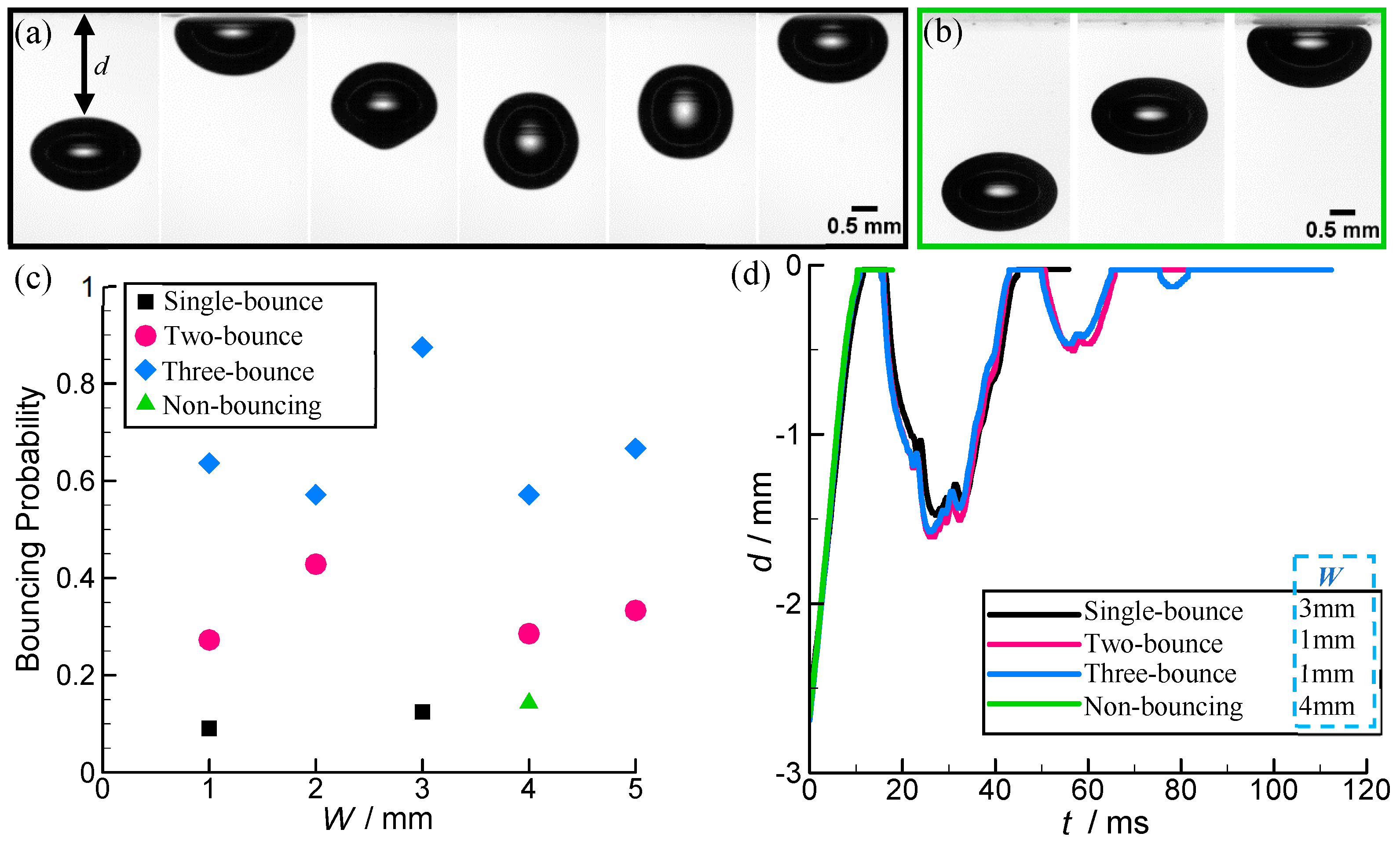
Sequence of snapshots of high-speed shadowgraph pictures illustrating the contact of bubbles with horizontal SALTs or SALS are presented in Figure 3. The time interval between adjacent frames is 8.6 ms and 5 ms for single-bounce (Figure 3a) and non-bouncing (Figure 3b), respectively.
Many previous researches indicated that bubbles tend to bounce when they approach a solid plate [10,21] and they are not sensitive to the normal wettability of the surface (aerophilic/hydrophobic or aerophobic/hydrophilic) [22]. The bouncing almost occurs with the bouncing probability of about 100%; however, the surface superaerophilicity can decrease this bouncing probability and results in non-bouncing before spreading [15]. As can be observed, the bouncing mostly happened when the bubble collided with SALTs (superaerophilicity) of different widths, and in our findings, non-bouncing only takes place for W = 4 mm. This behavior agrees with the previous results [15] but with a significantly higher bouncing probability, as shown in Figure 3c. Due to the wall-effect, despite the surface wettability, the liquid film between the wall and the bubble was drained and the shape of the bubble oscillates [23], and it tends to bounce downward against the direction of the buoyancy force. During this process, part of the total energy is dissipated due to viscous loss [2], and then, the spherical bubble at the largest depth can return to the approach to the wall for its second collision if the total remaining energy is enough. After repeated bouncing motions several times, the energy has completely dissipated, and the bubble transits to be flattened and stops on the wall. When it comes to the SALSs [15] or SALTs (present work), the bubble will perform spreading after exceeding this dynamical threshold. The whole bouncing processes for SALTs are described using d(t) plotted as a function of time t, and some typical cases are shown in Figure 3d. A high consistency was found for the evolution of d(t) between these bubble-wall collisions at different W and bounce times. This property indicates that neither SALTs’ width nor bounce times have a significant influence on the d(t) evolution before bubble spreading. Compared with the similar superaerophilic solids [15], a similar d(t) evolution can be seen for the bubble colliding with the SALTs; that is, the rebound amplitude sharply decreased as the bounce time increased.
Except for W = 4 mm, the bubbles always execute multi-time rebounds on the SALTs with the bouncing probability of 100%, while the bouncing probability has fallen from 100% to 85% for W = 4 mm, and the bubble may spread after the first touch to the surface rather than bounce back, as seen in Figure 3b. Clearly, as seen in Figure 3c, the bouncing probability is highest for three-bounce (above 55%) and is lowest for single-bounce (~10%, W = 1 mm, 3 mm) or non-bouncing (~15%, W = 4 mm). As reported by De Maleprade et al. [15], during the bubble approaching the superaerophilic surface, it decreases linearly, and the water layer between the bubble and SALT is gradually squeezed away. At the moment, a thin plastron of air on the superaerophilic surface will induce slips [15]. In the present work, when W exceeds a critical value (~4 mm), bubbles may stop on the SALT without bouncing, but the probability of non-bouncing is significantly smaller than that for the bubbles contacting the superaerophilic walls (~60%) [15]. This change can be attributed to the difference in the coating methods between our study (spray) and that of De Maleprade et al. [15] (dip-evaporation), which may build a thicker coating with lower uniformity, and this will be discussed further in Section 3.3.

3.2. Bubble Anisotropic Spreading on the SALTs

As proposed by several critical previous studies [15,18], the spreading of bubbles after contacting the SALS is very rapid, with a characteristic time of about 10 ms, and the spreading velocity, which usually corresponds to the moving contact line, can be up to ~4 m/s. To our knowledge, however, existing studies are limited to the isotropic (or quasi-isotropic) spreading of bubbles contacting walls of uniform wettability (hydrophobic, hydrophilic, aerophilic, and aerophobic). It is interesting to look what will happen if the bubbles are spreading on a surface of anisotropic aerophilicity, such as on SALTs. Consequently, the similarities and differences between the spreading of the flattened bubbles, after bouncing, contacting the uniform SALSs and SALTs are discussed from a bubble dynamical point of view.
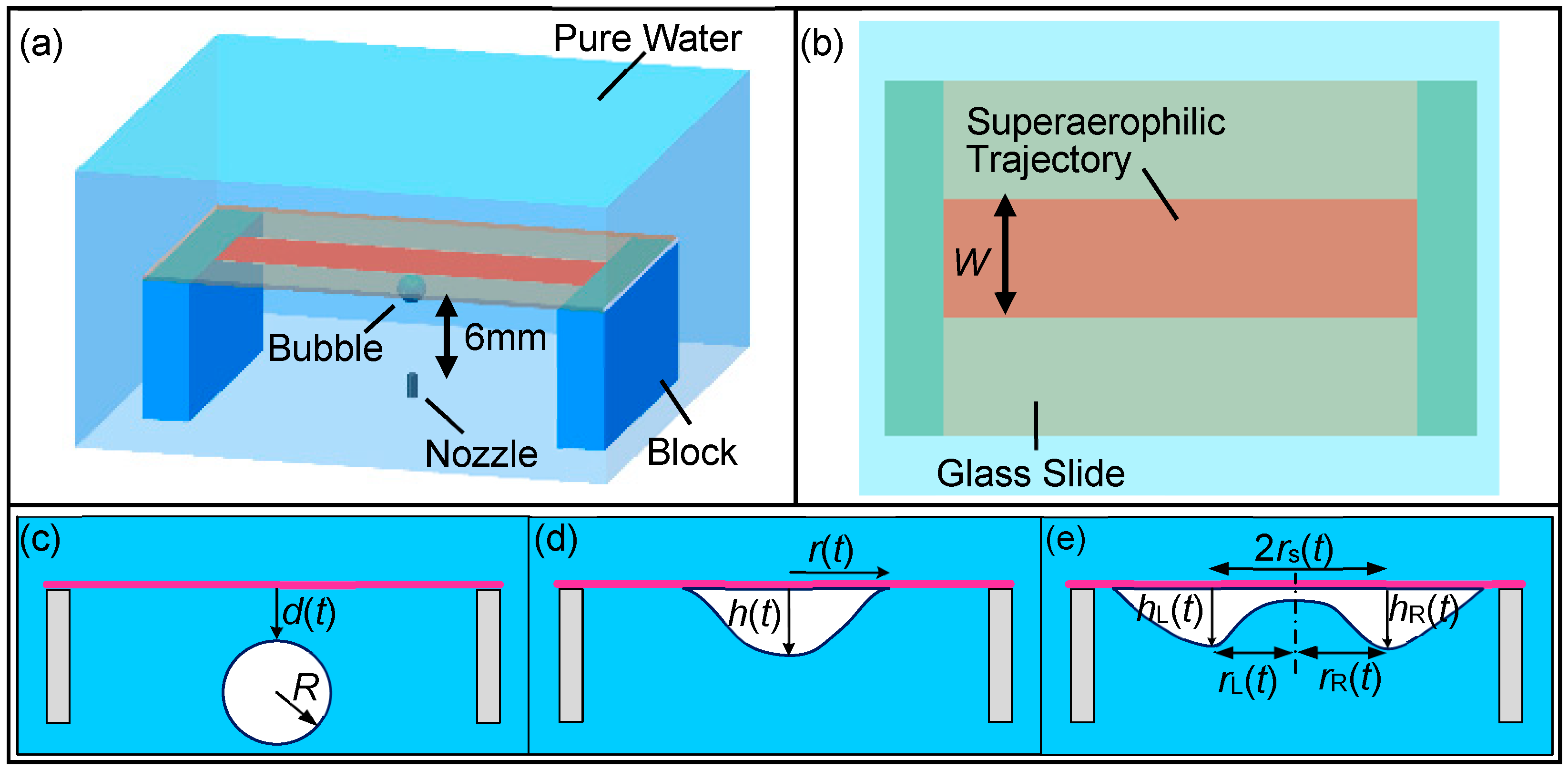
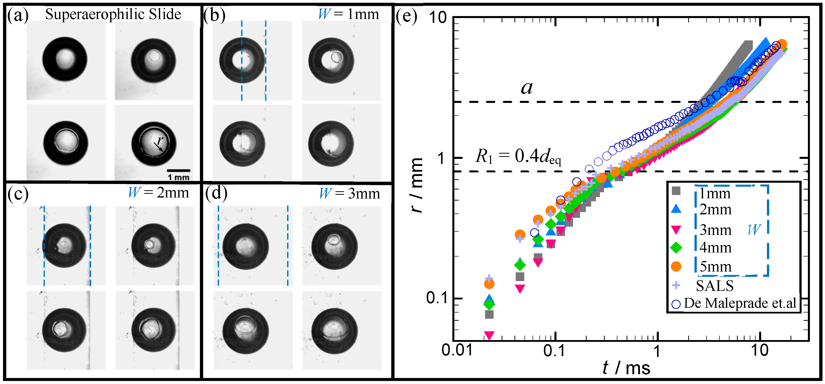
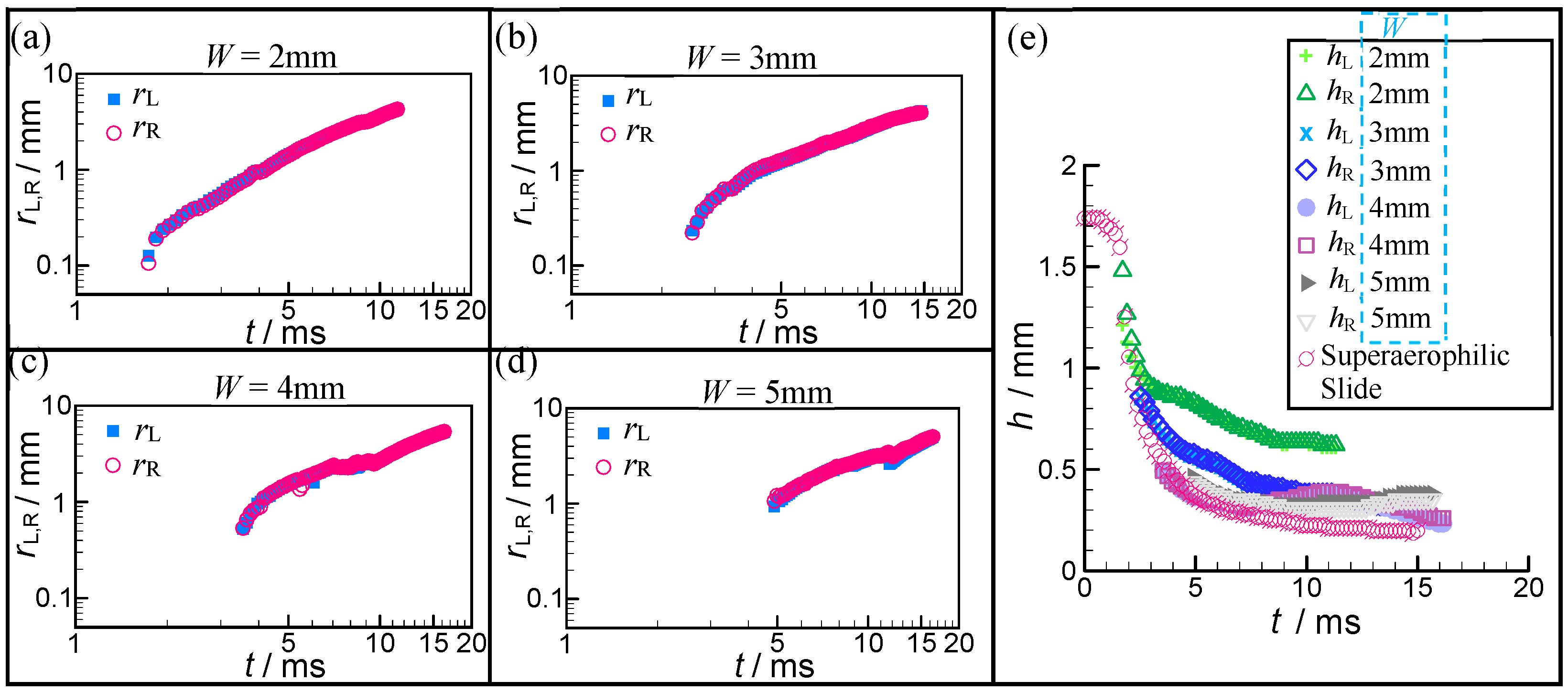
It is clear that the bubble, owing to the anisotropic aerophilicity distributed on the SALTs, will perform anisotropic spreading along the SALTs, and two contact lines moving in the opposite direction (left and right from side-view) will be formed. Half of the distance between the two outside contact lines (approximately perpendicular to the SALT at r(t) > 0.5deq) is denoted as the contact size of the SALTs (r), like SALS, and then rL and rR denote the respective distances of the left contact lines and the right contact lines to the point of puncturing, where the rupture of the fluid layer between the bubble and the SALT first happens. According to the spreading velocity (which equals the change rate of the contact size r) and the interface dynamics, the isotropic spreading of the bubble on the SALS with uniform superaerophilicity can be divided into three dynamical stages: rt at r < R1 (= 0.4deq), rt1/3 at R1 < r < a, and rt1/2 at r > a, as suggested by De Maleprade et al. [15]. Where a = ( γ / ρ g ) 1 / 2 (~2.5 mm for water) is the capillary length, γ is the surface tension, ρ is the fluid density, and g is the gravity acceleration. As shown in Figure 4e, the evolution of r(t) on SALS in our experiments (Lavender plus, present work) and that in the previous study [15] (blue circle) is very similar. However, there is still a distinguishable deviation between them, that may be related to the different preparation methods: dipping utilized by De Maleprade et al. [15] and spray by us for the superaerophilic surface. Additionally, the different definitions of the initial moment of the spreading can lead to this deviation. This earlier study provides insights into the mechanisms underlying the whole dynamical process of the bubble fast spreading on the SALS. In addition to these three dynamical stages, a short transition regime (r~a = 2.5 mm) is identified for SALSs and the wider SALTs (W = 3 mm–5 mm), and a new model of higher accuracy is proposed to replace the corresponding previous model at the third stage (r > a).
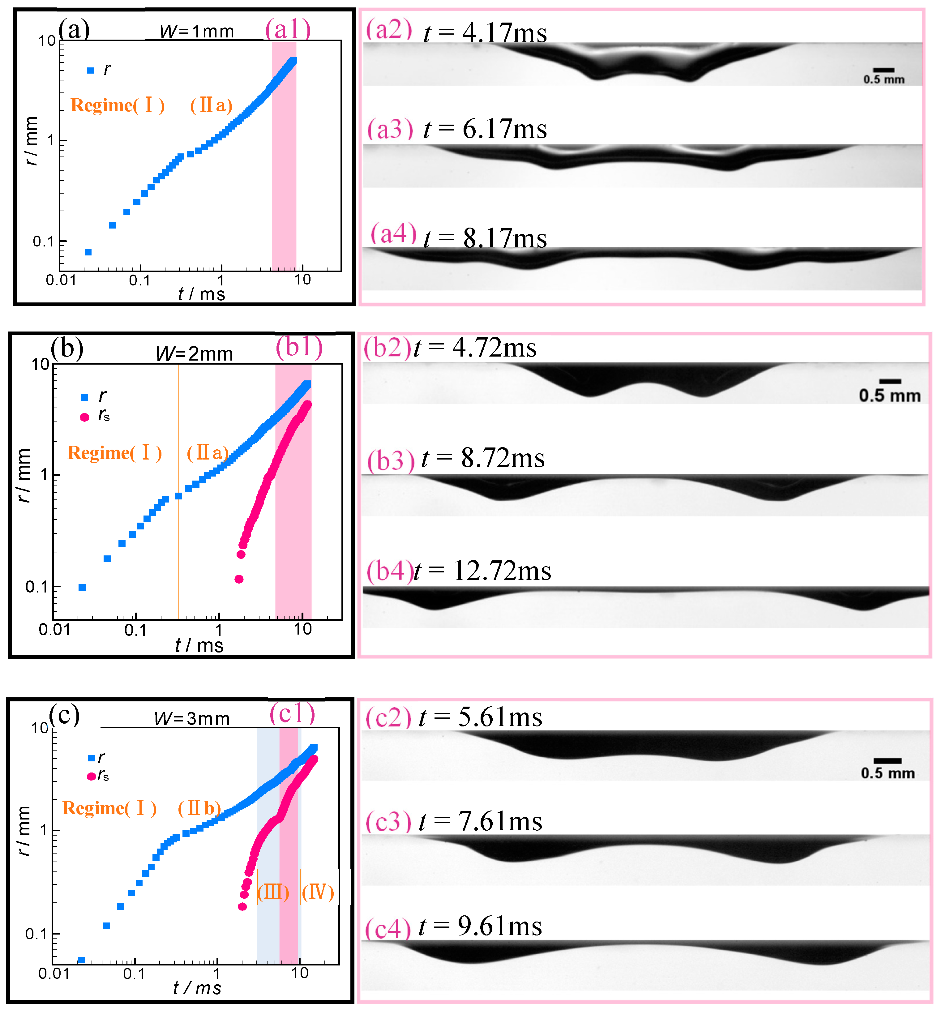
During the first regime, the bubble suffers a rapid spreading within a short time (< 3 ms) on both the SALSs and SALTs, and the contact size r is proportionally related to time t at r < R1, as shown in the Figure 4e. Figure 4a–d showed the top view of the moving contact lines, which resulted in the circular rims for SALSs and SALTs with W = 1 mm, 2 mm, 3 mm, respectively, and this highly dynamic behavior was captured using a high-speed at a rate of 89,000 fps, and the blue dashed lines indicated the boundaries of the SALTs. After the squeezed water between the flattened bubbles and the aerophilic surfaces (coated by a thin plastron of air) being punctured, this water film of thickness δ retracts, and then the contact line expands [15]. Note that the puncture of this intervening film cannot be triggered, and no bubble spreading occurred at SALT widths below 1mm (W = 0.5 mm).
Where this retracting water film can be treated as a horizontal ruptured soap film, which had been modeled by Culick [24] based on balancing surface tension 2γ and inertia ρδV2, and a constant retraction velocity can be given:
V = ( 2 γ / ρ δ ) 1 / 2
where the factor of 2 is here because the water film has two sides. Thus, the linear relation between r and time is identified:
r ( t ) = ( 2 γ ρ δ ) 1 / 2 t
Regarding the spreading velocity being stable around 4 ± 0.4 m/s, as reported by De Maleprade et al. [15], this relation implies a film thickness δ = 9 ± 2 μm. Despite using the different coating methods, the spreading velocity on both SALSs and SALTs measured in our experiments ranged from 3.0 m/s to 4.1 m/s, agreeing well with that of this previous literature [15]. Thus, we can say that the anisotropic aerophilicity of the SALTs has a slight effect on the spreading of the bubble in the first regime, even at SALTs’ widths smaller than the bubble radius. It is noted that the scattered data in the first regime (t < 3 ms) are all obtained from a typical test without averaging. The highly linear relation between r and time also can be found for SALTs of different widths during the initial spreading.
The linear r-t relations of both SALSs and SALTs in the first regime change at about t ≈ 0.3 ms with rR1 (= 0.4deq), and two different typical r(t)-t relations with different numbers of subregimes emerge for W = 1–2 mm and other wider SALTs and SALSs, respectively. Like the previous work [15], the spreading of bubbles is divided into three subregimes: for SALTs of W = 3–5 mm and SALS, denoted as regime (IIb), regime (III) and regime (IV). Note that the transition regime (III) has not been discussed yet, though it can be easily identified in Figure 3d at t ≈ 5.5 ms in this reference. Where (b) indicates the subregime corresponding to the SALTs of W = 3–5 mm and SALS, and thus, regime (IIa) denotes the second subregime for the narrower SALTs (W = 1 and 2 mm). Due to ra (~2.5 mm) in regime (IIb), the contact size is smaller than the SALT width (≥3 mm), and then the SALT can be equivalent to the SALS. Considering these results and bubble volume conservation of Ω ~ hr2, the balance of dynamical pressure ρV2 (at high Reynold number ~1000) with Laplace pressure γh/r2, as proposed by reference [15], yields
r ( t ) ( γ Ω ρ ) 1 / 6 t 1 / 3
This inertiocapillary law with the exponent of 1/3 agrees well with the corresponding data, as presented in Figure 4e. This power law suggests that the effects of resisted inertia and Laplace pressure is dominant in regime (IIb).
In the reference [15], the upper boundary of the regime (IIb) is fixed at the capillary length ~2.5 mm; whereas, in our study, the surface geometry determines it, which decreases with the decreasing W, as shown in Figure 5. For the SALTs of W = 4 mm and 5 mm, and SALS, the spreading bubble would experience a short transition (~1ms and named regime (III)), which also can be seen in Figure 4d from the reference [15], but is hardly mentioned, while the interval of regime (III) for W = 3 mm would be significantly expanded. The detailed views of these transitional regimes are presented in Figure 6. This property seems related to the bubble rupture and will be discussed in Section 3.3.
Further, De Maleprade et al. [15] deduced that the contact size exceeding r = a would grow following a power law with an exponent of 1/2, depending on the balance between the hydrostatic pressure (ρgh) and the water inertia (ρV2). During h ≤ 0.8 mm in this inertia-hydrostatic regime (the third stage in their study), just the spreading velocity of ~ 10−2 m/s can be generated by h of this velocity level. It is obvious that the hydrostatic energy is too slight to provide a practical spreading velocity of ~ 0.3 m/s, and thus, it is not the dominant driving force for the spreading of the bubble. The propagating bubbles in regime (IV) for SALTs of 3–5mm would be ruptured into two similar sub-bubbles with a velocity of ~ 0.3 m/s (Re~O2). Therefore, it can be inferred that the dominant driving force is the surface tension related to the superaerophilicity, and the dominant resistance is the water inertia. Inspired by the model of the retracting soap film with two surfaces [24], and regarding the only single side of the bubble interface, the balance between the surface tension γ and the inertia ρδV2 leads to
r ( t ) γ ρ h L , R t
where hL,R is the characteristic height of the ruptured bubble (at left or right), and it is denoted as h for SALS, as seen in Figure 1. Based on hL,R in the range of 0.2 mm–0.4 mm at t > 6 ms corresponding to the regime (IV), the spreading velocity predicted from Equation (4) ranges from 0.4 m/s to 0.6 m/s, which is close to the measurement results 0.3 m/s ≤ V ≤ 0.44 m/s. Additionally, the data in Figure 4 showed a significantly better fit to this linear relation (R2~0.98) than to the power-law with an exponent of 1/2 (R2~0.5). This finding reconfirms the above r(t)-t linear relation.
As further enhancing the anisotropic wettability by narrowing SALTs to W = 1 and 2 mm, the relations obtained above (regimes (II)–(IV)) for other, wider SALTs and SALS is invalid, and a unified sub-regime (regime (IIa)) over a broad time interval (t > 0.3 ms) emerges. In other words, only two major subregimes can be found for 1-mm and 2-mm SALTs, and the r(t)-t linear relations in their first regimes agree well with that for other SALTs and SALS. It is very interesting to find that the bubbles can spread observably faster on SALTs of W = 1 and 2 mm than on other SALTs and SALS. It would be curious to elucidate what happens to this increase in the bubble spreading velocity. Note that applying Equation (4) to the spreading of bubbles on SALTs of smaller widths (W = 1 and 2 mm) with the larger sub-bubble heights (~0.6 mm–0.7 mm corresponding to V of ~ 0.3 m/s) gives smaller V than that for other SALTs and SALS, contrary to our experimental data (V = 0.77 m/s and 0.51 m/s for W = 1 and 2 mm, respectively) in Figure 4e. This contradiction implies that there are other key factors, in addition to the surface tension, motivating the bubble spreading on the narrower SALTs. With concerning the remarkably increase in h for W = 1 and 2 mm, the more curved bubble interfaces in the transverse direction—in particular, near the two peak values of h—can be formed, and it is reasonably assumed that the Laplace pressure is another dominant driving force to accelerate the spreading. By summing the two principal velocity components derived from the surface tension and Laplace pressure (in transverse), respectively, the spreading velocity on these two narrower SALTs can be obtained as
r ( t ) ( γ h ρ R T 2 + γ ρ h ) t
The first term on the right of the expression accounts for the effect of the Laplace pressure, while the remaining term is associated with the surface tension effect of the SALTs on the bubble interface. Where RT is the curvature radius in the transverse direction and can be calculated by
R T = ( W 2 / 8 h ) + h / 2
using the circular segment assumption, as proposed by Wu et al. [6]. A high agreement between this extended model and the experiments was unexpectedly found using the time-averaged (t > 6 ms) values of h. More precisely, the bubble spreading velocity in regime (IIa) predicted by this expression is 0.76 m/s and 0.51 m/s for W = 1 mm and 2 mm, respectively, and the corresponding experimental results are 0.77 m/s and 0.53 m/s, with the relative deviation below 5%. This agreement demonstrates that the combined effect of the Laplace pressure and the surface tension on the two narrow SALTs prevails over other driving forces for the bubble spreading in regime (IIa).

3.3. Bubble Rupture on the SALTs

With the help of the anisotropic superaerophilicity of SALT, the bubble ruptures as it spreads on the SALTs (W = 2–5 mm) is observed first, and two sub-bubbles with similar sizes and velocities but in the opposite directions along the SALT were generated, as shown in Figure 5 and Figure 7. Note that the bubble interface necking at W = 1 mm cannot be defined as a rupture, due to the gas layer between their two humps too thick to be distinguished from the humps (Figure 7(a2–a4)). Compared to the SALTs, SALSs cannot result in the rupture of the flattened bubbles. It is interesting to note that the migration velocity of the two ruptured bubbles is higher (>0.3 m/s) than that of the moving contact lines (Figure 7(b1–e1)), and their transport distance can be ~10mm in our experiments. This migration capacity of the ruptured bubbles provides a potential solution for the horizontally directional transport of the bubble in aqueous environments. Ma et al. recently proposed this interesting topic [19], using the geometry gradient of the SALS to transport the bubble horizontally. Once the two sub-bubble humps established as a result of the interface necking before rupture, a high degree of symmetry in the two ruptured bubbles, including the migration velocity and bubble geometry, can be found during this whole dynamical process (Figure 5 and Figure 7). Additionally, the decrease in W accelerates the necking of the initial bubble, such as 2 ms after puncture for W = 2 mm but 5ms after puncture for W = 5 mm. The SALTs of W = 1 and 2 mm induce thicker bubbles (with a larger height of 0.5 mm–0.6 mm) than that at 3 mm ≤ W ≤ 5 mm do (0.2 mm < h < 0.38 mm), owing to their narrower widths leading to the stronger constraint effects on the bubble interface in the transverse direction. Although the remarkable difference between the SALT at W = 2 mm and other wider SALTs and SALS in the threshold of necking and bubble height was demonstrated above (Figure 5), the bubble rupture also occurred at W = 2 mm (Figure 7(b2–b4)). Considering the high consistency of r(t)-t curves with only two subregimes between the 2 mm SALT and 1 mm SALT, we can say that the bubble rupture exerts a slight influence on the contact propagation but is closely related to the SALT width.
To further understand the ruptured bubble motion, the center-to-center distance rs(t) between the ruptured bubbles was plotted as a function of t simultaneously, compared to the contact size r(t), in Figure 7 For the wider SALTs of 3 mm ≤ W ≤ 5 mm, the bubble interface necking approximately happened around the transitional regime (regime(III)), and the increase in W decreased the time gap between the necking and the regime(III) and postponed the necking. Like r(t)-t curves during regime(III), the more apparent fluctuations of rs(t) take place lagging behind that of r(t), and it can be smoothed as the SALT width decreased from 5 mm to 3 mm and almost disappeared at W = 2 mm (no similar fluctuation for r(t)-t curves). This correlation suggested that the fluctuation on r(t)-t curves may induce that on rs(t)-t curves, and the fluctuation is strengthened after the propagation. As analyzed in Section 3.2, a thicker air film retained on the narrower SALTs (such as W = 2 mm and 3 mm) would produce a stronger Laplace pressure, because of their higher transverse bending, to resist the interface necking. As a result, the r(t) and rs(t) change curves show a sharper fluctuation on them at the wider SALTs (W = 4 mm and 5 mm) and SALS, compared to that at other, narrow SALTs. Furthermore, the transitional regime can be expanded as the SALTs narrow (Figure 7), for the same reason.

4. Conclusions

Anisotropic spreading of bubbles (deq = 2 mm) on superaerophilic straight trajectories (SALTs) of different widths (0.5 mm ≤ W ≤ 5 mm) beneath a slide in water was experimentally studied using a high-speed shadowgraphy system, and the superaerophilic surface SALS and SALTs were constructed using spray coating with a silica nanoparticle solution. With the constant initial gap between the bubbles and the slide d0 = 4 mm, the bouncing mostly happened as the bubble contacted the SALTs, except for non-bouncing at W = 4 mm. The bouncing probability of SALTs is significantly higher than that in the previous study [15]. It was found that SALT widths and bounce times hardly affect the evolution of d(t). After the repeated bouncing, the bubble becomes flattened and stops on the wall for a short while (~ O (101) ms), and then the thin film between the bubble interface and SALT (or SALS) would be punctured to trigger the rapid spreading process. Two essential mechanisms are found to be responsible for the anisotropic spreading on the narrow SALTs (W = 1 mm and 2 mm) and the wide SALTs (3 mm ≤ W ≤ 5 mm), as characterized by the different evolution of the contact lines and quantified using the r(t)-t curves. In addition to the three dynamical stages as proposed by De Maleprade et al. for SALS [15] (r(t) ∝ t at r < 0.4deq, r(t) ∝ t1/3 at 0.4deq < r(t) < a, and r(t) ∝ t1/2 at r(t) > a corresponding to the major driving forces of the SALT tension effect, Laplace pressure, and hydrostatic pressure, respectively), we identified a short transitional regime (regime (III) at r~a = 2.5 mm), which was missing in the previous study, for SALS and the wider SALTs (W = 3 mm–5 mm). We further model the contact size in regime (IV) as a linear function of time to demonstrate the surface tension effect of SALTs prevailing over the hydrostatic pressure. Compared to the wide SALTs, the enhanced constraint effect of the narrow SALTs (W = 1 mm and 2 mm) on the bubble interface in the transverse direction results in a novel evolution mechanism composed of only two subregimes. The former subregime is similar to that at 3 mm ≤ W ≤ 5 mm, while the latter one shows a linear relation between contact size and time. A simple model has been developed to depict this linear relation in regime (IIa) concerning the combined effect of the surface tension effect of the SALT and Laplace pressure. This model and our experiments are in nice agreement.
Further, we first observed that the initial flattened bubble ruptured into two sub-bubbles with similar sizes and migration velocities in opposite directions during its anisotropic spreading on the SALTs at 2 mm ≤ W ≤ 5 mm. The ruptured sub-bubble pair are highly symmetric around the puncture center, concerning the bubble geometry and velocity. The bubble rupture can be attributed to the strong anisotropic-superaerophilicity of the SALT and seems to be related to the apparent fluctuations on the change curves of r(t) and rs(t). It is interesting to find that the decrease in W will smooth these fluctuations, owing to the stronger Laplace pressure generated by the smaller curvature radius of the remaining air film on the narrower SALTs to better withstand the interface necking caused by the hydrostatic effect. It is unavoidable to arrange some engineering structures horizontally in the aqueous environments, such as the electrodes of fuel cells and the heat exchangers, where the bubble accumulation on the horizontal surfaces are usually undesired. In contrast, underwater vehicles or ships covered by a thin plastron of air can achieve lower hydrodynamic resistance [25,26]. Through SALTs, the bubble can be directionally transported at a velocity of about 0.4 ± 0.1 m/s for a medium distance, and the gas film can be effectively constrained into the designated surface area of these engineering structures on demand.

Author Contributions

Conceptualization, C.T.; methodology, Q.Y., Y.Y., Y.W., S.Y., P.D., and C.T.; formal analysis, Z.Y., R.J., and X.L.; investigation, Y.C., Z.Y., R.J., and X.L.; writing—original draft preparation, C.T., Y.C., and Q.Y.; and writing—review and editing, C.T. and F.B.; All authors have read and agreed to the published version of the manuscript.

Funding

This research received no external funding.

Acknowledgments

This work was supported by the National Natural Science Foundation of China (Grants No. 11972334, No. 11672284, No. 11632016, No. 11872217, and No.51871206) and the National Key R&D Program of China (Grant no.2017YFB0603701).

Conflicts of Interest

The authors declare no conflicts of interest.

References

  1. Seymour, R.S.; Matthews, P.G. Physical gills in diving insects and spiders: Theory and experiment. J. Exp. Biol. 2013, 216, 164–170. [Google Scholar] [CrossRef] [PubMed] [Green Version]
  2. Parker, A.R.; Lawrence, C.R. Water capture by a desert beetle. Nature 2001, 414, 33. [Google Scholar] [CrossRef] [PubMed]
  3. Zheng, Y.; Bai, H.; Huang, Z.; Tian, X.; Nie, F.-Q.; Zhao, Y.; Zhai, J.; Jiang, L. Directional water collection on wetted spider silk. Nature 2010, 463, 640–643. [Google Scholar] [CrossRef] [PubMed]
  4. Kamei, J.; Saito, Y.; Yabu, H. Biomimetic ultra-bubble-repellent surfaces based on a self-organized honeycomb film. Langmuir 2014, 30, 14118–14122. [Google Scholar] [CrossRef] [PubMed]
  5. Yang, Q.; Li, T.; Lu, Z.; Sun, X.; Liu, J. Hierarchical construction of an ultrathin layered double hydroxide nanoarray for highly-efficient oxygen evolution reaction. Nanoscale 2014, 6, 11789–11794. [Google Scholar] [CrossRef] [PubMed]
  6. Wu, C.-J.; Chang, C.-C.; Sheng, Y.-J.; Tsao, H.-K. Extraordinarily rapid rise of tiny bubbles sliding beneath superhydrophobic surfaces. Langmuir 2017, 33, 1326–1331. [Google Scholar] [CrossRef] [PubMed]
  7. Yu, C.; Zhu, X.; Cao, M.; Yu, C.; Li, K.; Jiang, L. Superhydrophobic helix: Controllable and directional bubble transport in an aqueous environment. J. Mater. Chem. A 2016, 4, 16865–16870. [Google Scholar] [CrossRef]
  8. Huppert, H.E. The propagation of two-dimensional and axisymmetric viscous gravity currents over a rigid horizontal surface. J. Fluid Mech. 1982, 121, 43–58. [Google Scholar] [CrossRef] [Green Version]
  9. Tanner, L. The spreading of silicone oil drops on horizontal surfaces. J. Phys. D Appl. Phys. 1979, 12, 1473. [Google Scholar] [CrossRef]
  10. Zenit, R.; Legendre, D. The coefficient of restitution for air bubbles colliding against solid walls in viscous liquids. Phys. Fluids 2009, 21, 083306. [Google Scholar] [CrossRef]
  11. Manica, R.; Klaseboer, E.; Chan, D.Y. Force balance model for bubble rise, impact, and bounce from solid surfaces. Langmuir 2015, 31, 6763–6772. [Google Scholar] [CrossRef] [PubMed]
  12. Zawala, J.; Malysa, K. Influence of the impact velocity and size of the film formed on bubble coalescence time at water surface. Langmuir 2011, 27, 2250–2257. [Google Scholar] [CrossRef] [PubMed]
  13. Tsao, H.K.; Koch, D.L. Observations of high Reynolds number bubbles interacting with a rigid wall. Phys. Fluids 1997, 9, 44–56. [Google Scholar] [CrossRef]
  14. Pelletier, E.; Béguin, C.; Étienne, S. Experiments of air bubbles impacting a rigid wall in tap water. Phys. Fluids 2015, 27, 123302. [Google Scholar] [CrossRef]
  15. De Maleprade, H.; Clanet, C.; Quéré, D. Spreading of bubbles after contacting the lower side of an aerophilic slide immersed in water. Phys. Rev. Lett. 2016, 117, 094501. [Google Scholar] [CrossRef]
  16. Jeong, H.; Park, H. Near-wall rising behaviour of a deformable bubble at high Reynolds number. J. Fluid Mech. 2015, 771, 564–594. [Google Scholar] [CrossRef]
  17. Javadi, K.; Davoudian, S.H. Surface wettability effect on the rising of a bubble attached to a vertical wall. Int. J. Multiph. Flow 2018, 109, 178–190. [Google Scholar] [CrossRef]
  18. Wang, J.; Zheng, Y.; Nie, F.-Q.; Zhai, J.; Jiang, L. Air bubble bursting effect of lotus leaf. Langmuir 2009, 25, 14129–14134. [Google Scholar] [CrossRef]
  19. Ma, H.; Cao, M.; Zhang, C.; Bei, Z.; Li, K.; Yu, C.; Jiang, L. Directional and Continuous Transport of Gas Bubbles on Superaerophilic Geometry-Gradient Surfaces in Aqueous Environments. Adv. Funct. Mater. 2018, 28, 1705091. [Google Scholar] [CrossRef]
  20. Levich, B.; Landau, L. Dragging of a liquid by a moving plate. Acta Physicochim. URSS 1942, 17, 42. [Google Scholar]
  21. Zawala, J.; Krasowska, M.; Dabros, T.; Malysa, K. Influence of bubble kinetic energy on its bouncing during collisions with various interfaces. Can. J. Chem. Eng. 2007, 85, 669–678. [Google Scholar] [CrossRef]
  22. Zawala, J.; Dabros, T. Analysis of energy balance during collision of an air bubble with a solid wall. Phys. Fluids 2013, 25, 123101. [Google Scholar] [CrossRef]
  23. Sato, A.; Shirota, M.; Sanada, T.; Watanabe, M. Modeling of bouncing of a single clean bubble on a free surface. Phys. Fluids 2011, 23, 013307. [Google Scholar] [CrossRef]
  24. Culick, F. Comments on a ruptured soap film. J. Appl. Phys. 1960, 31, 1128–1129. [Google Scholar] [CrossRef] [Green Version]
  25. Kavalenka, M.N.; Vüllers, F.; Lischker, S.; Zeiger, C.; Hopf, A.; Röhrig, M.; Rapp, B.E.; Worgull, M.; Hölscher, H. Bioinspired air-retaining nanofur for drag reduction. ACS Appl. Mater. Interfaces 2015, 7, 10651–10655. [Google Scholar] [CrossRef]
  26. Jones, P.R.; Hao, X.; Cruz-Chu, E.R.; Rykaczewski, K.; Nandy, K.; Schutzius, T.M.; Varanasi, K.K.; Megaridis, C.M.; Walther, J.H.; Koumoutsakos, P. Sustaining dry surfaces under water. Sci. Rep. 2015, 5, 12311. [Google Scholar] [CrossRef] [Green Version]
Figure 1. SEM images. (a) Large-area SEM image of the surface of the SALTs. (b) Enlarged view from (a).
Water 12 00798 g001
Figure 2. Experimental setup. (a) Schematic of the experimental system. (b) Schematic of the superaerophilic trajectories (SALT) and the SALT characterized by its width, W. (c) An air bubble of radius R before contacting the superaerophilic slide or SALT. (d) The spreading of the bubble occurs after contact. (e) The bubble rupture takes place on a SALT (W = 2–5 mm) after the transition to a critical r(t).
Water 12 00798 g002
Figure 3. Bubble dynamics during contacting SALTs’ different widths (W) of with r = 1 mm. Sequence of snapshots of a bubble colliding with the SALT before spreading: either bubbles experience bounce off the surface for single-bounce (a) to three-bounce or non-bouncing (b), and the last image both in (a) and (b) show that the bubbles stop with their flattened shapes on the trajectory just before their spreading. Images are separated by 8.6 ms and 5 ms for the single-bounce case (a) and the non-bouncing case (b), respectively. (c) Probability of bouncing against the SALTs of different W. (d) The vertical position (depth) of the bubble d as a function of time t, and d = 0 corresponds to the depth of the SALTs’ low side.
Water 12 00798 g003
Figure 4. Spreading of flattened bubbles on the superaerophilic surface (SALS) and SALTs of different widths. (a)–(d) Top view of the propagation of contact lines for SALS and SALTs with W = 1 mm, 2 mm, and 3 mm, respectively; the interval between adjacent images is “∆t ≈ 56 μs”, and the blue dashed lines indicate the boundaries of the SALTs. (e) Contact size r plotted as a function of time t for the bubble of deq = 2 mm on SALTs of different widths depicted with different symbols; R1 ≈ 0.8 mm means the upper boundary of the initial spreading driven by the capillary effect, and a = ( γ / ρ g ) 1 / 2 (~2.5 mm) is the capillary length.
Water 12 00798 g004
Figure 5. Contact size (rL and rR) and thickness of the two ruptured bubbles plotted as a function of time t. (a)–(d) The rL, R-t curves at W = 2 mm, 3 mm, 4 mm, and 5 mm, respectively. (e) The thickness of the two ruptured bubbles plotted as a function of t at different SALT widths.
Water 12 00798 g005
Figure 6. The detailed views corresponding to the concentrated transitional regime (regime (Ⅲ)) of the r-t curves in Figure 4e around ra.
Water 12 00798 g006
Figure 7. Interface evolution of bubbles spreading on SALTs and SALS. (a)–(e) Correspond to the SALT widths ranged from 1 mm to 5 mm, and (f) corresponds to the SALS. The left subfigures (a1)–(f1) illustrate the contact size r (blue square) and the center-to-center distance rs (pink circle) between the ruptured bubbles as a function of t. The right subfigures (except (a1)–(f1)) show the sequence of snapshots (side view) of a bubble spreading (or rupture) on the SALTs and SALS, and their spans correspond to the areas marked in dark pink in the left subfigures. The areas marked in light blue indicate the transitional regime (regime (III)) of the contact propagation. Vertical orange lines mark the boundaries of the dynamical subregimes, which are labeled at the corresponding subregimes.
Water 12 00798 g007aWater 12 00798 g007b

