Parametric Terracing as Optimization of Controlled Slope Intervention


Faculty of Architecture, University of Ljubljana, Zoisova 12, 1000 Ljubljana, Slovenia
*
Author to whom correspondence should be addressed.
Water 2020, 12(3), 634; https://doi.org/10.3390/w12030634
Submission received: 31 December 2019
/
Revised: 17 February 2020
/
Accepted: 21 February 2020
/
Published: 26 February 2020
(This article belongs to the Special Issue Terraced Landscapes and Hydrological-Geological Hazards)
Abstract
:With the introduction of mechanization in agriculture, the area of terraced slopes has increased. However, in most cases, the planning of terracing in practice remains experience-based, which is no longer effective from an agricultural, geological, and hydrological point of view. The usual method of building terraces, especially terraces with earth risers, is therefore outdated, and a new method must be found for planning and building terraced areas. In addition to geographical information system (GIS) tools, parametric design tools for planning terraced landscapes are now available. Based on the design approaches for a selected plot in the Gorizia Hills in Slovenia, where we used a trial-and-error method, we improved previous results by defining a model using a computer algorithm that generates a terraced landscape on a selected slope depending on various input parameters such as the height of the terrace slope, the inclination of the terrace slope, the width of the terrace platform, and the number of terraces. For the definition of the algorithm we used the visual program tool Grasshopper. By changing the values of the input data parameters, the algorithm was able to present combinatorial simulations through a variety of different solutions with all the corresponding statistics. With such results it is much easier to make a conscious decision on which combination of parameters is optimal to prevent landslides, plan adequate drainage, and control soil movements when building terraces. The controlled slope intervention is further optimized by the introduction of a usage index (Tx), defined as the quotient of the sum of all flat areas (terrace platforms) and the total area of the plot.
1. Introduction
Terraces are a global phenomenon, and their emergence is the result of various terrain, climate, and social factors. They can be found almost everywhere in the world, but they are very different in use, size, shape, and construction. In the vast majority of cases, their main function is to increase the area of arable land in places where tillage is either impossible or very difficult owing to poor soil or steep slopes. Terraces have a positive influence on higher crop yields by improving soil quality (but not in all cases [1]) and on better quality of harvests due to the better sun exposure of the plants. They can be part of a water management system, maintain the stability of the terrain, prevent erosion, and, last but not least, have a positive influence on the visual appearance of the landscape.
The formation of terraces is a consequence of many factors. For example, terraces are one of the most obvious human interventions in the landscape and cover large areas of the Earth [2], they reduce slope gradient and length, they facilitate cultivation on steep slopes, and they have a generally positive effect on the integration of agricultural activities [3]: only well-lit grape leaves can be as photosynthetically active as possible [4].
In addition to the fact that terraces preserve more agricultural land, they were also built to decrease hydrological hazards and erosion [5]. Terraced landscapes offer aesthetic, social, and ecological values due to their biodiversity and biotopes [6].
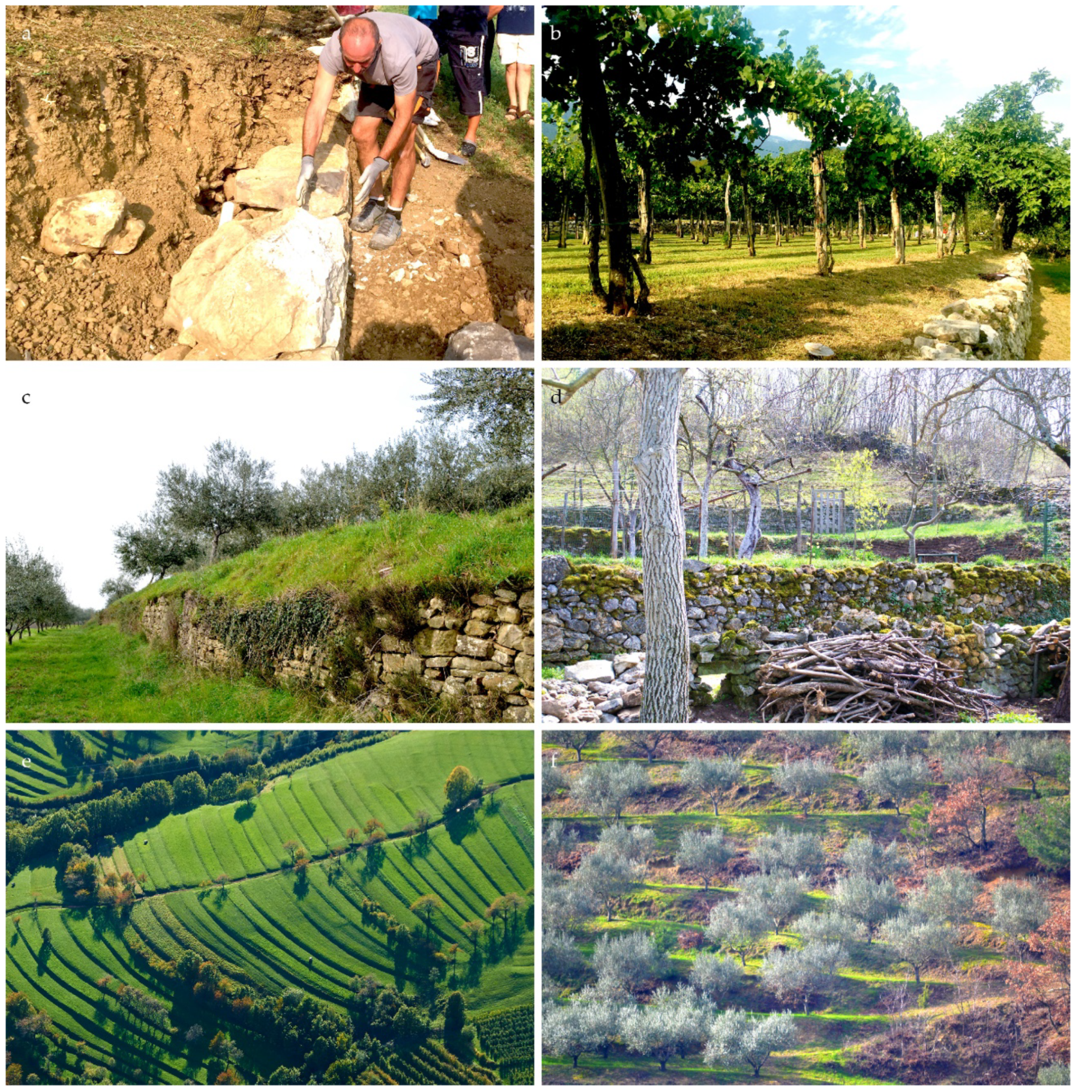
In the past, slopes were manually terraced and terraces were planned based on local needs and knowledge was passed down from generation to generation. In the United States as early as 1931, an examination of terraces on farms revealed that the causes of terrace failures were due to the terraces being poorly planned, improperly laid out, inadequately built, or carelessly maintained [7]. One of the outstanding causes of terrace failures is the failure to prevent water from draining away from a terraced field. Most historical terraces are of the bench type with dry stone walls [2]. Until the Second World War, the slopes were cultivated and terraced by hand (Figure 1) [8].
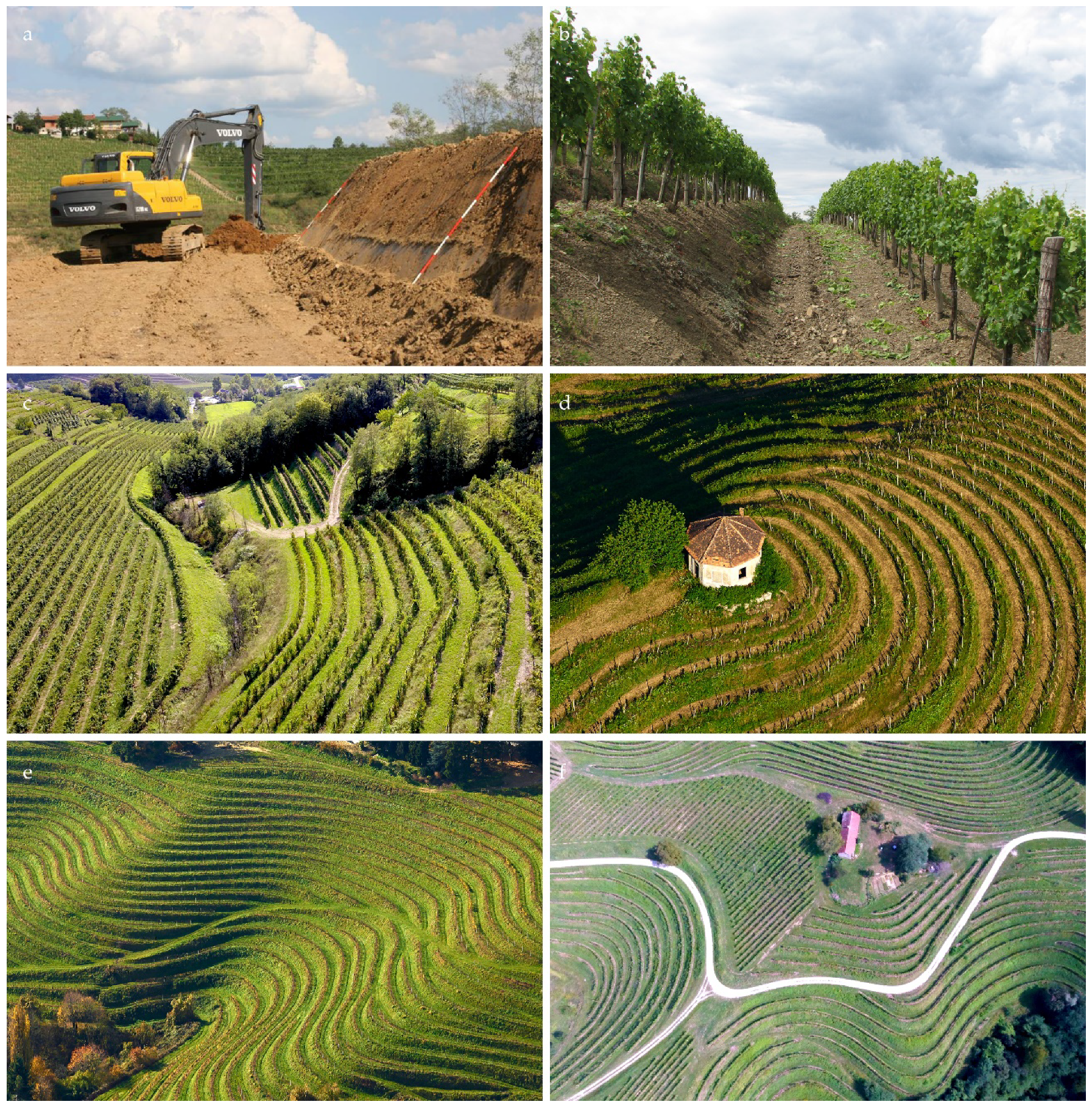
Agricultural mechanization has changed farming [9] (Figure 2). In some places it became much easier to maintain, renew, and build new terraces. Mechanized work replaced arduous manual labor [10], and knowledge about handmade terraces was partly lost or was adapted to new construction methods, but remained at an experience level.
The extensive terracing in eastern Europe in the 1960s and 1970s was a consequence of agricultural organization in the communist social system, in which farmers had to join agricultural collectives. Working with machines in large vineyards was of course easier than the heavy manual labor in traditional vineyards [11]. The areas intended for terracing and the slopes where terracing was carried out were enlarged [12] and the distance to settlements was increased.
However, the experience-based planning of terraces is no longer effective, and therefore the intervention of experts with plans and a developed planning method are needed.
Mechanization enabled farmers to first level the entire slope surface in order to obtain an even slope. Terraces were cut into the set slope, which could be made relatively even by using mechanization [13]. However, if agricultural interventions to prepare vineyards or other plantations change the shape of the slope and create steeper slopes than those created by nature through the long process of geomorphic transformation, one can expect that sooner or later more or less extensive areas of soil instability will appear on them. In such cases, additional safety should be provided; for example, with retaining walls to provide additional stability. The change in slope geometry or form over time can mean that the entire landscape becomes increasingly vulnerable to extreme weather events, especially extreme precipitation and the resulting water volumes, and that stability gradually decreases in large slope sections [14].
The use of machines—which allow for much larger slope interventions in a much shorter timeframe than, for example, in the manual management of agricultural land—also requires a different approach to planning such interventions, especially because a variety of software programs and procedures are now available that can be planned in advance for both the intervention and its consequences. The traditional way of building terraces, especially for terraces with earthen slopes, is therefore outdated, and a new methodology for planning and building terraced areas must be found.
Some authors state that the impact of mechanization is greatly under-explored in steep-slope cultivation systems, for example, for agricultural terraces [15]. Nonetheless, traditional terrace systems have been widely transformed to allow the use of machinery in recent decades [16], and newly planted vineyards have also been adapted for labor-saving mechanization [17].
1.1. Terrace Planning and Construction
The ALPTER project (Interreg project The Terraced Landscapes of the Alpine Arc, 2005–2008) reviewed the degradation of agricultural terraces caused by agricultural abandonment in the Alps [18] and the possibilities for rehabilitating these terraced spaces [19].
In the ALPTER project, for the first time one of the partners studying terraced systems was from Slovenia (the University of Ljubljana’s Faculty of Architecture, ULFA). ULFA also prepared the plan and built new terraces in the settlement of Medana. An exceptional feature of the arrangement of the vineyard terraces in Medana was creating a plan for building the terraces. The construction method was innovative, new, and applicable to previously terraced slopes or ones that had not yet been terraced. The most important innovation was collaboration with an architect, who drew up the plan for building the terraces, which included a series of interdisciplinary preparations in addition to the actual design phase.
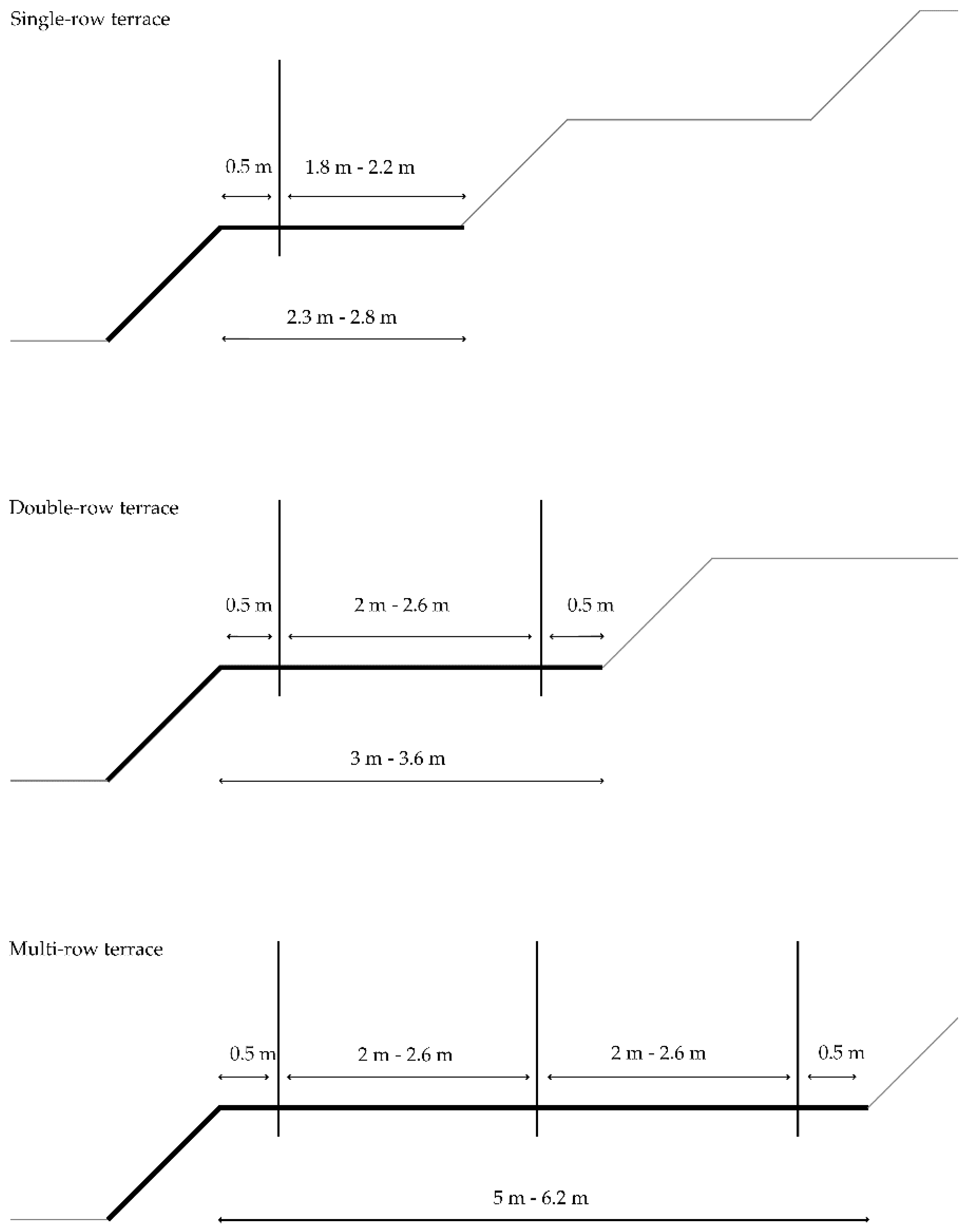
Agricultural recommendations for terrace arrangements for vineyards and orchards were considered when preparing the plan [20]. According to the recommendations, the vines in a vineyard can be arranged in single-row terraces, double-row terraces, double-row terraces with a passage for tractor between the row and the slope, or multi-row terraces (Figure 3). Orchards can be arranged in a single row, with fruit trees at the edge of the terrace or on the slope of the terrace [21].
The composition of the base soil was investigated with ten exploration shafts. Photos of the plan and individual phases can be seen in the book Terasirana pokrajina Goriških brd (Terraced Landscapes of the Gorizia Hills) [22], which shows cross sections of the terrain prior to terracing, cross-sections of the terrain according to the plan, the construction plan for the terraced area, and photos of the plot of the land before, during, and after building the terraces.
The book Terraced Landscapes of the Alps [23] features some pictures and an explanation of the methodology used to prepare the terraces.
The greatest advantages of GIS are its analytical capabilities for connecting and presenting multiple layers of a location in a multidimensional and georeferenced way. Data such as geology, soil type, type of infrastructure, and so on can be used for the design or selection of locations. GIS offers a dynamic way of presenting invisible patterns of sociocultural, socioeconomic, behavioral, or demographic data [24]. GIS tools are compatible with all established visualization tools to create attractive dynamic and complex models. Nevertheless, the experience of architectural practice and research is still limited when applying GIS techniques [25].
For this first so-called GIS architectural method, the sequence of steps was as follows [26]:
– Selection of the location for the terracing. For building the terraces, a plot located by the side of the main road from Dobrovo to Vipolže was chosen. It is easily accessible, has a triangular shape, and has an area of 0.93 hectares.
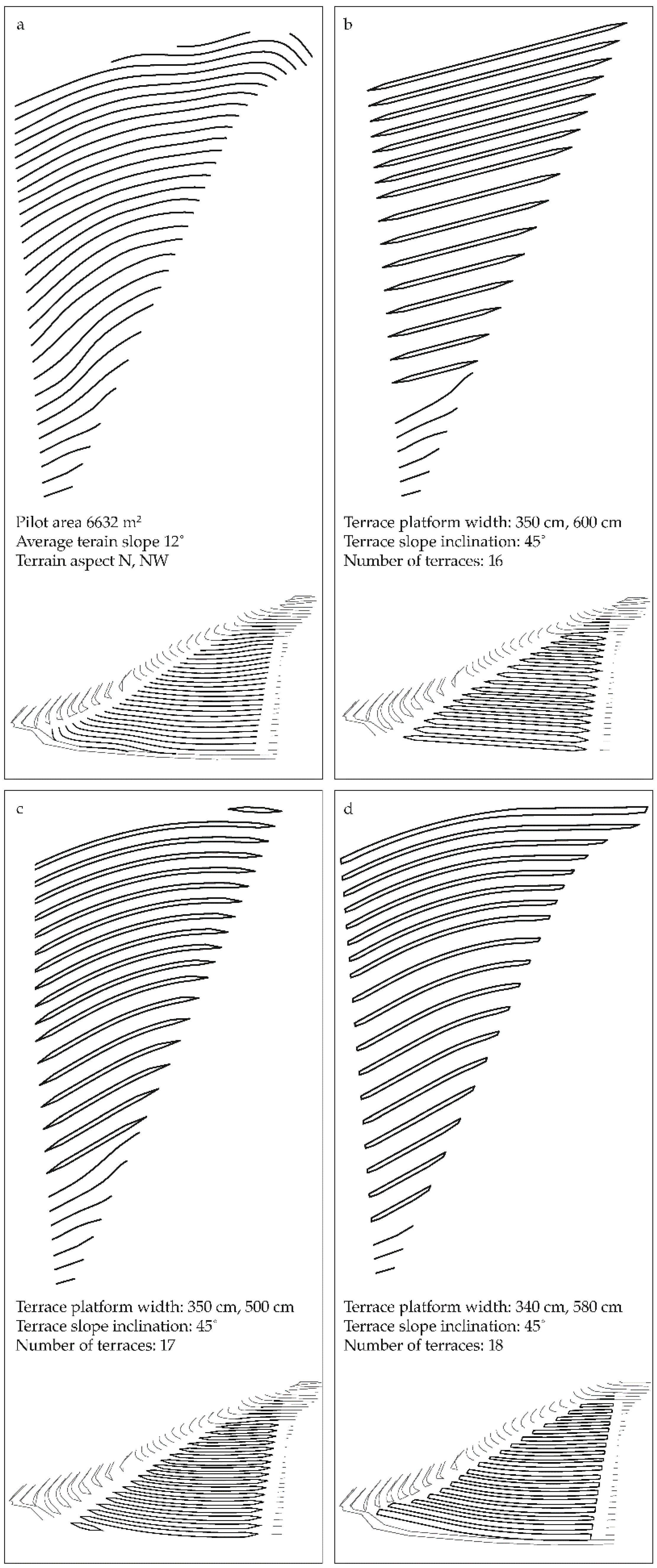
– Geodetic measurement of the plot with contour lines (Figure 4a.).
– On the basis of one-meter elevation contour lines, a digital elevation model (DEM) was created using GIS tools.
– DEM was used for a number of terrain analyses such as terrain aspect, hydrology tools, and slope inclination. Using GIS tools such as the slope tool and the flow direction tool, we determined that the lower part of the plot is steeper with an inclination of 23 to 26%, whereas the upper part has an inclination of 15 to 17%. The flow direction tool showed that water on the surface of the slope runs in three directions.
Standard geomechanical laboratory procedures were used to determine the physical properties and shear strength of the soil on the slope [27]. The relationship between rainfall and terrace landslide vulnerability was also evaluated, which only a few studies address in general [28] and not solely for terraced slopes. The soils in the chosen slope can be divided into two characteristic groups: weathered clay and very weathered soft marl under the weathered layer. The measured physical and mechanical properties of the soil show that the existing hillsides cannot be remodeled into steeper slopes without the help of additional supporting structures. Very low angled banks are imposed by the properties of gray marl, which crumbles and deteriorates when exposed to the air, and by the properties of the weathered clay, which lies on impermeable layers of marl and within which interconnected layers of groundwater form during rainfall. The study concluded [29] that tillage of the flysch bedrock could be a source for expanding unstable areas in the Gorizia Hills due to the progressive flysch bedrock decay and should be avoided or accompanied by additional construction measures, such as stone retaining walls, deep and surface drainage systems, or additional selected vegetation on terrace slopes, which draws water and functions as a reinforcement. The height and width of the terrace slopes should be configured at ratio of 1:1, and the lowest terrace slope at a ratio of 2:3 to improve the stability of the entire terraced area. Excess rainwater should be drawn away from the terrace platform by a slight inclination of a minimum of 0.5% to a maximum of 2% via the road to the drainage system. Drainage should be prepared to carry off groundwater and other sources of water. Because no springs of groundwater could be found on the slope, such a drainage system was not needed. Terraced platforms should also have a slight inclination in the transverse direction to carry the excess water toward plants and vegetation on the terrace slope.
Based on these facts, several plans were prepared. All the plans were a combination of approaches to adapting the cross-section and ground-plan to the geometry of the terrain.
The versions differed in layout or general design concept. The first plan had only straight terraces, which would make it easier to farm (Figure 4b). In the second version, the terraces were better adapted to the terrain and partially combined the existing terrain shape, and were therefore completely curved (Figure 4c). The third and final version of the model was a more ingenious combination of the first two, which also took into account the different technical requirements for pathways, drainage, and access, and it more closely approximated the contour lines in the field (Figure 4d).
When the outline was drawn up, all the variants had to be tested in the 3D model. For each 2D plan a 3D wireframe model was prepared and transferred to the GIS application of ESRI ArcDesktop (Version 10.6. ESRI Environmental Systems Research Institute, Redlands, CA, USA). Here it was compared with a survey of the original terrain and analyzed using the cut fill function, which provided information about soil movements during the transformation of the existing terrain into the final version and about the excess material. The general rule was that there should be no surplus of soil on the plot. By defining new heights of terraced slopes in virtual space it was possible to approximate this criterion. Minimal soil movement on the plot itself means more stable terrain, shorter construction time, and lower construction costs for the terraces.
1.2. Research Questions
In planning the terraces on the selected plot, we used the trial-and-error method. This is a common method in architectural planning. However, the results raise several research questions. Due to time and financial reasons, the planned variations of the terraced vineyard were limited to a few initial versions and one final version. Despite careful planning, several variations could not be tested, which means that we cannot be sure that the final variant was optimal, for example, in terms of achieving the largest terrace platform area (m2) and consequently planting the largest number of grapevines. Digging provokes marl-softening processes. Such processes consequently lead to the following changes: thicker disintegrated clay layers on the slopes, increased water permeability of the surface layer, and the possibility of water penetrating deeper into the cracked flysch base. For these reasons it is important to follow the line of the stable configuration of the old terrain during planning and construction. The following research questions remained: Could we create (or choose) an even better version of terracing? Could the area utilization be greater? How can we be sure that the variation chosen is optimal, and how can we make the selection more objective? Is it possible to choose a new method and technology, and to achieve better results in all these aspects?
1.3. New Design Techniques in Architectural Practice
New design approaches, software programs, and techniques in architectural design change rapidly. Digital parametric design is part of general digital design (architecture) practice. Parametric design is based on the digital animation technique and has evolved over the last fifteen years, taking the lead in current avant-garde architecture [30].
In mathematics, a parameter indicates a series of values expressed as a function of independent values. In architecture, a parameter is understood as a value assigned to an element or factor. Parametric design is nowadays in the domain of object-oriented parametric design, which drives BIM tools, but textual and visual parametric programming languages and platforms that offer more (Building information modeling) freedom and interdisciplinary use are coming to the fore.
The first advantage of parametric design is that it allows the user to study a series of shapes by changing the value of only one parameter, changing the value of several parameters, or changing other design principles written in the algorithm. Parametric design allows changes without significant consequences (mainly considering time and cost) in later time periods of the design process. Most importantly, it provides a level of control over the design process that was unimaginable in the past.
The digitally parameterized design can be divided into the object design and the program design. Architectural software tools such as Revit and ArchiCAD can be defined as parametric because in each part of the design process the properties (dimensions, design, type, and materiality) of the required elements can be adjusted. Software parametric tools are designed in a different way, where there are very few predefined elements in the form of prefabricated complex objects (windows, doors, roofs, stairs, etc.) or they are very basic ones (basic volumes, lines, and points). They are only one set of commands in a component, which must be redefined with each new project.
The advantage of software parametric tools is that they are not limited in their scope and can be adapted to any task. Examples of parametric software tools include Microstation (Bentley Systems), Creo Suite (PTC), CATIA (Dassault Systèmes), Dynamo (Autodesk), and Grasshopper (Robert McNeel & Associates).
Grasshopper is a visual programming language and environment developed by David Rutten at Robert McNeel & Associates. By using a combination of sliders and mathematical and visual command components, it is possible to create very complex shapes or to calculate only certain parameters. The use of the visual programming language is very broad and ranges from graphic design and manipulation and drafting of complex architectural and urban planning designs to static checks, calculations, and simulations of natural and artificial processes.
1.4. Hypothesis
We argue that it is possible to define a computer algorithm that generates a terraced landscape on a selected slope depending on various input parameters such as terrace slope height, terrace slope inclination, width of the terrace platform (width of the one-row terrace, width of the double-row terrace, width of the multi-row terrace), and number of terraces.
We argue that the answer is provided by the concept of combinatorial simulation. The term is usually associated with biological or pharmaceutical research, in which different compounds and elements are mixed in different quantities or in sequences. Through a large number of variations of the same experiment, each with slightly different parameters, it is possible to see what effects new variations have on the environment and whether a random combination brings about demanded utilizations that cannot be predicted by intuition and knowledge.
We also argue that a similar process can be imitated by generative algorithms. This is the Rhino 3D “Grasshopper” plugin platform, where trends and directions of experiment development can be identified with the initial input of terrain characteristics and a set of rules with specific and repeatable steps, through which we can find many different solutions, but which do not necessarily differ greatly from each other.
2. Materials and Methods
The development of the algorithm is based on the 3D model design method used in the 2006 pilot project. Based on the design estimate, a two-dimensional CAD (computer-aided design) model was initially developed in two versions. The model took into account the dominant elements of the terrain that influenced its formation. The models were created with computer modeling design software Autodesk AutoCAD (Version O.49.0.0 AutoCAD 2018. Autodesk, San Rafael, CA, USA) and Autodesk 3DS Max (Version 19.0, 3D Max 2017. Autodesk, San Rafael, CA, USA), with the individual terrace raised to a certain height. The height of the terrace is derived from the coefficient of the height difference from the foot of the hill to the top of the newly terraced area and the number of terraces in the plan. We also adapted it to the slope of the terrain with terraces of different lengths. Therefore the model did not have a uniform matrix and consisted of longer three-row terraces in the flatter part and shorter two-row terraces in the steeper part of the plot. The terrace platform is defined by the upper slope edge of the previous terrace and the lower slope edge of the next terrace. As a rule, the inclination of the terrace platform from the center of the slope to the edges of the terrace platforms (in the longitudinal direction of the terraces) due to rainwater runoff should be taken into account, but this detail was not considered in the 3D model. The resulting contour lines of the model were therefore transferred to the ESRI ArcGIS Desktop. A DEM (Digital Elevation Model) grid layer with a cell size of 1 m × 1 m was created there. In the same way, the existing terrain was also created from the topographic data. These two terrains were deducted using the cut fill function, which was intended to calculate the volume difference between two different terrains in raster format. The results of the operation told us what the movements of the earth look like when changing from one model to another and whether there are any soil surpluses. The main guideline was to make the values as uniform as possible. Fewer land movements mean more stable terrain, shorter production time, and lower construction costs for terraces.
To develop the algorithm, it is important to predict the workflow and criteria, and to determine the parameters that will influence the algorithm. These parameters are the width of the terrace platform, the inclination of the slope, and the plot area for which the plan will be prepared.
The first and most important criterion is the width of the terrace platform, which is determined by the width of the machinery for working the land and maintaining the plants. This determines the type of planting of the terrace platforms and the extreme dimensions of the terraces and terrace platforms, which define the sequence of the single-row, double-row, and multi-row terraces. The inclination of the slope can be arbitrary, but by changing the inclination we also change the width of the entire terrace profile (terrace width = plan width of the terrace platform area + plan width of the slope area), which changes the width of the terrace platform. The algorithm calculates the width of the terrace platform based on the total width of the terrace and the slope inclination. To simplify the procedure, the algorithm calculates only one width of the terrace platform in the entire terrain and automatically adjusts the height of the slope.
The second criterion is the parameterized surface of the plot, which can be a snapshot of a real or completely fictional surface. The input surface must be normalized. The cross sections of the terrain are usually not parallel to each other, which means that the surface is usually dynamic. The model adapts terraces to the surface without normalizing the surface. The result are terraces that closely follow the general direction of the terrain, which means that the terraces (in the given case) are inclined and as such are not suitable for cultivation. Therefore the terrain must first be leveled. This work step is equivalent to the GIS function cut fill, which is also used in the work process described above. With certain terrain configurations, small, marginal distortions may occur.
The parameters based on the rules of the algorithm (Figure 5) determine the height of the slopes, the number of square meters of the area of the slopes, and the number of square meters of terrace platforms from which a 3D model of the terraced landscape is created, including all desired metrics. In contrast to the previously described work process method, in which the steps are not necessarily consecutive, in the case of the algorithm it is essential that there be no unknowns during the process flow. Because computer tools are not particularly innovative without prior intervention, the entire process must be defined and fixed in advance, or otherwise the algorithm will not work.
The first step is to enter the selected terrain at the beginning of the matrix. This action starts the calculation of the terrain abstraction into a lower resolution of the model, which is then divided into a grid of segments. The number of segments can be specified and can be changed during the analysis as needed. We perform this action with a component or a group of commands that divides the surface into a field of points. The default value is 100 × 100 points in the U and V directions and can be larger or smaller. It depends strongly on the available computing power. In 3D modeling we treat the dynamic surface as a plain. We project the 2D coordinates to the 3D model UV/XY, which gives us 10,201 points. Note that in Grasshopper counting starts at 0, and therefore we have the additional number 101 × 101 = 10,201 points at the coordinates U = 100 and V = 100.
The points are arranged so that we can draw the lines through a series of points from the top to the bottom edge of the terrain. All of these lines are divided into the desired width of the terrace, which is one of the main parameters. This parameter gives the final image of the terraced vineyard. We obtain a series of transverse lines that, through basic trigonometry, determine the extreme boundaries of the terrace platforms. On the outermost top line of the terraced platform we determine the points around which the next terrace slope is rotated. From the line elements obtained, the area of both the terrace slopes and the terrace platforms is obtained very quickly, which allows us to visually simulate the new situation and quickly generate new variations without any additional effort. As the slope changes from the maximum utilization of the terrace platform with a vertical slope (inclination of 90°) to the optimum inclination (45°), the area of the terrace platforms changes and with it the utilization of the area of the terrace platforms. It can be determined very quickly which option is quantitatively the most advantageous.
The algorithm is able to quickly calculate and generate a variety of 3D models and calculations of their properties such as the number of terraces, areas of terrace platforms, areas of terrace slopes, heights of all slopes, minimum and maximum slope heights, and the usage index of the terraced slope based on the parameters of slope inclination and width of the terrace platform.
The usage index of the terraced plot is defined as the quotient of the sum of the areas of all flat parts (terrace platforms) and the total area of the plot:
At,i is the area of i terrace platforms, and A is the total area of the plot. Results closer to 1 are considered better.
In this study we limited the study area to the narrower plot of the terraced slope, which includes only terraced areas (terraced platforms and slopes) without roads and without useless or overgrown plot areas. Such a smaller plot area was used as a basis for the calculations and a comparative study.
The decisive criterion for the design of the terraced landscape was the width of the terrace platforms because these are determined by the width of the machinery required for agricultural work. This determines the type of planting and the extreme dimensions of the terraces and terrace platforms, which are defined as single-row terraces, two-row terraces, and multi-row terraces.
3. Results
With the algorithm we were able to calculate the three most common terrace slope inclinations that occur in terraced terrain. The 90° angle is not suitable for terraces in the chosen area and requires wall support, but it has the best efficiency. The inclination of 66° corresponds to an inclination ratio of 3:2 (height, length), but it is still too steep. The inclination of 45° is used when the ratio is 1:1. To calculate inclination values below this ratio makes no sense because the work surface is lost.
The algorithm took into account different widths of the terrace platforms (single-row terrace, double-row terrace, and multi-row terrace). Consequently, the usage index was calculated for all widths of the terrace platform (single-row terrace: 230 cm, 270 cm; double-row terrace: 300 cm, 360 cm; multi-row terrace: 500 cm, 620 cm).
We started with a terrace width of 230 cm, which allows the construction of a single-row terrace and a slope inclination of 90° (Table 1). With these parameters we obtained a maximum usage index of the slope with 72 terraces: the lowest terrace height was 33 cm and the highest 66 cm. The usage index in this case is Tx = 0.98. When we changed the slope inclination to 66° and 45° (Figure 6a) using the same terrace platform width, the usage index dropped significantly to 0.84 and 0.77. The maximum height of the terraces was 84 cm and 134 cm, and the number of terraces 63 and 57. For the extreme dimensions of the single-row terraces with a terrace platform width of 270 cm, the usage indexes were identical: 0.98, 0.84, and 0.77. The number of terraces at an inclination of 90° is 61, at an inclination of 66° is 53, and at an inclination of 45° is 49. The slope heights were similar.
If we use the width of the terrace platform of 300 cm, which is the smallest possible terrace platform width of the two-row terraces, the results are very similar when using the maximum dimension of the terrace platform of single-row terraces. The usage indexes are also similar: 0.97, 0.84, and 0.77. The minimum height of the terrace slopes is 44 cm, 60 cm, and 78 cm, and the maximum height of the terrace slopes is 81 cm, 106 cm, and 148 cm. Compared to the results for single-row terraces, only the number of terraces has changed significantly: there are 55 terraces at a 90° inclination, 47 terraces at a 66° inclination, and 44 terraces at a 45° inclination. For double-row terraces with a width of 360 cm of the terrace platform, the usage indexes are similar to those for double-row terraces with a width of 300 cm of the terrace platform: Tx are 0.97, 0.83, and 0.76. The minimum heights of the terraces are 52 cm, 70 cm, and 91 cm, and the maximum heights of the terraces for different slope inclinations are between 95 cm, 122 cm, and 167 cm. The number of terraces decreases as the slope inclination decreases: now only 46, 40, and 37 (Figure 6b) terraces can be planned.
In the last type of terraces—three-row terraces or multi-row terraces—the width of the terrace platform is between 500 cm and 620 cm. With the width of the terrace platform of 500 cm and the inclination of the terrace slope of 90°, 66°, and 45°, the number of terraces decreases to 33, 29, and 26 (Figure 6c). The minimum heights of the terraces are 72 cm, 99 cm, and 127 cm, and the maximum heights of the terraces reach 124 cm, 182 cm, and 220 cm with usage index Tx at 0.96, 0.83, and 0.75. With a maximum terrace platform width of the multi-row terraces of 620 cm and the same sequence of slope terrace inclinations, we obtain Tx 0.95, 082, and 0.75. The number of terraces decreases and is only 27, 23, and 21 (Figure 6d). The minimum height of the terraces is between 87 cm, 124 cm, and 161 cm, and the maximum terrace heights are between 150 cm, 218 cm, and up to an extreme of 278 cm.
4. Discussion
Of particular interest is the comparison between the previous plan variations of the terraces made according to the GIS architectural method in 2006. When evaluating the results, it has to be considered that, based on the algorithm, the model automatically adapts to the terrain and automatically generates the shape of the terrain. This is why there are no longer straight terraces or a combination of straight and curved terraces in the plan. The outcome of the model is an optimal plan of the terraces, which are slightly curved in our case.
For the 2006 terraced landscape plan, the values regarding the terrace metrics are already known (Table 2). The usage index is 0.75 for straight terraces, 0.7 for curved terraces, and 0.73 for the final plan. Surprisingly, the Tx is highest for the straight terraces, although this variation does not take into account the inclination of the slope of the terrain and the use of the plot down to its last part.
The Tx of the combinatorial simulation shows that largest usage index is when the terrace slopes are vertical (90°). This result is indicative because the algorithm has neglected the wall thickness required by such construction of the terrace slope. Namely, the physical and mechanical properties of the soil from the chosen location show that steeper slopes or slopes at an inclination of 90° cannot be constructed without the help of additional supporting structures due to soil erosion. Dry stone walls have a certain width. If there are a large number of terraces with dry stone walls, the wall thickness can significantly reduce the area of the terrace platforms. Taking the wall thickness into account would increase the sum of the terrace slope area by a considerable amount, which would affect both the Tx and the number of terraces.
If the terrace slope inclination is 66° or 45°, this problem does not exist. We know from both empirical field measurements as well as from geomechanical measurements in the selected location that the break between the terrace slope and the terrace platform (as shown in Figure 3) is without any additional soil bundle between the two terrace elements, and that the optimum slope inclination, taking into account soil stability, is 45°. In addition, the vegetation and its roots also improve the stability of the soil due to drawing water, although vegetation is a complex and highly variable biological material and it is difficult to predict its mechanical reinforcement of the soil.
Therefore, the optimal scenario for the construction of terraces with modern machinery would be one in which the inclination of the slope of the terrace is 45°. The usage index varies between 0.77 (single-row terrace, double-row terrace) and 0.75 (multi-row terrace). There are 44 double-row terraces with terrace platforms 300 cm wide and a terrace height between 78 cm and 148 cm, and there are 21 multi-row terraces with terrace platforms 620 cm wide and a terrace height between 161 cm and 278 cm. The first option is better, not only because of the simpler construction of the terraces, but also to avoid bureaucratic problems: a building permit is required if the height of the terrace exceeds 1.5 m.
Interestingly, the usage index at a terrace slope inclination of 45° is very similar, although not entirely identical, to the mode of operation in 2006, which confirms that the model works and its results are relevant. Most interesting is the alternative arrangement of the new terraces on the plot, which was determined by the algorithm, which is an additional argument for the application of this planning methodology. The greatest benefit is the calculation of the different heights of the terraces, which would have been quite complicated and time-consuming with the previous planning method. The matrix (Table 1) shows which variations do not come into selection because the height of the terraces is too low: it is generally considered that terraces with a height less than 1 m are not built.
When building terraces, it is important to make the inclinations of the terrace slope in such a way that the slopes remain stable without landslides. The terrace slopes also need to become overgrown with greenery in a short time, which helps water absorption. Terrace platforms are inclined in two directions: transverse and longitudinal. It is possible that the algorithm could not only provide additional statistics in terms of the number of vines, annual wine yield, and other economic indicators, but also hydrological control, because it would be much easier to calculate the drainage system for adequate amounts of water and to calculate soil losses due to both regular rainfall and extreme events.
We have shown that technology has great potential for optimizing the design process in terraced landscapes. The algorithm makes it possible for both less- and more-experienced professionals to use such a construction method.
Of course, many improvements can be made to the algorithm. Runoff and landslide risk–related variables of terraces designs can be part of future model development. It would be possible for the algorithm to adjust different terrace platform lengths according to the slope of the terrain, which would improve the accuracy of the results and make the algorithm not only a gadget but also a construction and statistical tool.
In the future, with the help of an extended database, the algorithm could choose the optimal version by itself, not only in terms of terrace platform areas (m2) or the number of vines, but also in terms of ease of construction, cost, and the simplest agricultural working method.
With some effort toward the further development of the algorithm based on the characteristics of the plot and some input parameters, it would be possible to extract the slope plans with all the relevant statistics. At a municipal or state level, a web application based only on available digital terrain data (Lidar) for use by persons involved in planning, agriculture, or soil protection is within reach, to be applied to a selection of single or multiple plots of land to obtain an assessment of how the plots can be developed.
Author Contributions
Conceptualization, T.B. and L.A.-M.; methodology, T.B.; software, T.B.; validation, L.A.-M.; formal analysis, T.B. and L.A.-M.; investigation, T.B. and L.A.-M.; resources, T.B. and L.A.-M.; data curation, T.B. and L.A.-M.; writing—original draft preparation, T.B. and L.A.-M.; writing—review and editing, T.B. and L.A.-M.; visualization, T.B. and L.A.-M. All authors have read and agreed to the published version of the manuscript.
Funding
This research received no external funding.
Acknowledgments
The authors thank Simon Petrovčič for advice and assistance in mathematically defining the equation for the terraced area usage index.
Conflicts of Interest
The authors declare no conflict of interest.
References
- Posthumus, H.; Stroosnijder, L. To terrace or not: The short-term impact of bench terraces on soil properties and crop response in the Peruvian Andes. Environ. Dev. Sustain. 2010, 12, 263–276. [Google Scholar] [CrossRef]
- Tarolli, P.; Preti, F.; Romano, N. Terraced landscapes: From an old best practice to a potential hazard for soil degradation due to land abandonment. Anthropocene 2014, 6, 10–25. [Google Scholar] [CrossRef]
- Tarolli, P.; Sofia, G.; Calligaro, S.; Prosdocimi, M.; Preti, F.; Dalla Fontana, G. Vineyards in Terraced Landscapes: New Opportunities from Lidar Data. Land Degrad. Dev. 2014, 26, 92–102. [Google Scholar] [CrossRef]
- Ažman Momirski, L. Terasirana pokrajina. In Terasirana pokrajina Goriških brd; Perko, D., Kladnik, D., Eds.; Založba ZRC: Ljubljana, Slovenia, 2008; pp. 98–118. [Google Scholar]
- Lasanta, T.; Arnáez, J.; Oserín, M.; Ortigosa, L. Marginal Lands and Erosion in Terraced Fields in the Mediterranean Mountains. Mt Res. Dev. 2001, 21, 69–76. [Google Scholar] [CrossRef]
- Höchtl, F.; Ruşdea, E.; Schaich, H.; Wattendorf, P.; Bieling, C.; Reeg, T.; Konold, W. Building bridges, crossing borders: Integrative approaches to rural landscape management in Europe. Nor. Geografisk Tidsskr.-Norw. J. Geogr. 2007, 61, 157–169. [Google Scholar] [CrossRef]
- Eisenhower, M.S. (Ed.) Yearbook of Agriculture 1931. United States Department of Agriculture, 1931. Available online: https://archive.org/details/yoa1931/page/n1/mode/2up (accessed on 27 January 2020).
- Bertovič, M.; Andlar, G. The Grey Istria Cultural Landscape–The Analysis of Town of Oprtalj Terraced Landscape. Ann. Istrian Mediterr. Stud. (ANNALES Series Historia et Sociologia) 2019, 29, 101–124. [Google Scholar] [CrossRef]
- Tavares, T.d.O.; de Oliveira, B.R.; Silva, V.d.A.; Pereira da Silva, R.; dos Santos, A.F.; Okida, E.S. The times, movements and operational efficiency of mechanized coffee harvesting in sloped areas. PLoS ONE 2019, 14. Available online: https://doi.org/10.1371/journal.pone.0217286 (accessed on 27 January 2020). [CrossRef] [PubMed]
- Varotto, M.; Bonardi, L.; Tarolli, P. (Eds.) World Terraced Landscapes: History, Environment, Quality of Life; Springer: Cham, Switzerland, 2019; pp. 1–356. [Google Scholar]
- Štefunková, D.; Hanušin, J. Viticultural landscapes: Localised transformations over the past 150 years through an analysis of three case studies in Slovakia. Moravian Geog. Rep. 2019, 27, 155–168. [Google Scholar] [CrossRef] [Green Version]
- Lieskovský, J.; Kenderessy, P.; Špulerová, J.; Lieskovský, T.; Koleda, P.; Kienast, F.; Gimmi, U. Factors Affecting the Persistence of Traditional Agricultural Landscapes in Slovakia during the Collectivization of Agriculture. Landscape Ecol. 2014, 29, 867–877. [Google Scholar]
- Škvarč, A.; Kodrič, I. Nature and regulation: Management of vineyards and orchards on terraces. Urbani izziv 2006, 17, 78–84. [Google Scholar] [CrossRef]
- Ažman Momirski, L. Kulturne terase v severnih Goriških brdih na primeru katastrske občine in naselja Kožbana. In Terasirana pokrajina Goriških brd; Perko, D., Kladnik, D., Eds.; Založba ZRC: Ljubljana, Slovenia, 2008; pp. 139–155. [Google Scholar]
- Pijl, A.; Barneveld, P.; Mauri, L.; Borsato, E.; Grigolato, S.; Tarolli, P. Impact of mechanisation on soil loss in terraced vineyard landscapes. Geog. Res. Lett. 2019, 45, 287–308. [Google Scholar] [CrossRef] [Green Version]
- Ramos, M.C.; Cots-Folch, R.; Martínez-Casasnovas, J.A. Sustainability of modern land terracing for vineyard plantation in a mediterranean mountain environment–The case of the Priorat Region (NE Spain). Geomorphology 2007, 86, 1–11. [Google Scholar] [CrossRef]
- Ramos, M.C.; Benito, C.; Martínez-Casasnovas, J.A. Simulating soil conservation measures to control soil and nutrient losses in a small, vineyard dominated, basin. Agric. Ecosyst. Environ. 2015, 213, 194–208. [Google Scholar] [CrossRef]
- Alpter. Available online: http://predmet.fa.uni-lj.si/alpter/terraced-landscapes.html (accessed on 19 December 2019).
- Scaramellini, G.; Varotto, M. (Eds.) Terraced Landscapes of the Alps: Atlante, (Progetto Alpter); Marsilio: Venezia, Italy, 2008; Available online: https://www.alpter.net/IMG/pdf/ALPTER_Atlas_ENG_small.pdf (accessed on 23 February 2020).
- Ažman Momirski, L. Kulturne terase v južnih Goriških brdih na primeru katastrske občine in naselja Medana. In Terasirana pokrajina Goriških brd; Perko, D., Kladnik, D., Eds.; Založba ZRC: Ljubljana, Slovenia, 2008; pp. 119–138. [Google Scholar]
- Škvarč, A. Renewal of the Vineyard. Knowledge as a Determining Factor in Agricultural Development; KGZNG: Dobrovo, Slovenia, 1999. [Google Scholar]
- Ažman Momirski, L.; Kladnik, D.; Komac, B.; Petek, F.; Repolusk, P.; Zorn, M. Terraced Landscapes of the Gorizia Hills; Založba ZRC: Ljubljana, Slovenia, 2008; pp. 1–197. [Google Scholar]
- Ažman Momirski, L.; Škvarč, A.; Kodrič, I. The terraces of Goriška Brda—Case study of Medana. In Paesaggi Terrazzati Dell’arco Alpino; Fontanari, E., Patassini, D., Eds.; Marsilio: Venice, Italy, 2008; pp. 40–46. [Google Scholar]
- Zeiger, M. Meet the Geodesigner. ARCHITECT: The Magazine of the American Institute of Architects. 2010. Available online: https://www.architectmagazine.com/technology/gis-and-data-enriched-design_o (accessed on 17 December 2019).
- Moore, J. GIS for Architecture. Research Guides, WU Libraries. 2013. Available online: http://libguides.wustl.edu/gisforarchitecture (accessed on 1 May 2017).
- Ažman Momirski, L.; Berčič, B.; Škvarč, A.; Kodrič, I. Guidelines for the Arrangement of Permanent Planting on Terraces: The Case of Vineyard Renewal in the Goriška; University of Ljubljana, Faculty of Architecture: Ljubljana, Slovenia, 2007. [Google Scholar]
- Majes, B.; Petkovšek, A.; Klopčič, J. Geotechnical Treatment of the Vineyard Renewal on the Flysch Slope—A model Example for "Medana"; University of Ljubljana, Faculty for Civil and Geodetic Engineering: Ljubljana, Slovenia, 2006. [Google Scholar]
- Rupp, S.; Wohlers, A.; Damm, B. Long-term relationship between landslide occurrences and precipitation in southern Lower Saxony and northern Hesse. J. Geomorphol. 2018, 61, 327–338. [Google Scholar] [CrossRef]
- Petkovšek, A.; Klopčič, J.; Majes, B. Terraced landscapes and their influence on the slope stability. In Living Terraced Landscapes: Perspectives and Strategies to Revitalise the Abandoned Regions; Ažman Momirski, L., Černič Mali, B., Eds.; University of Ljubljana: Ljubljana, Slovenia, 2008. [Google Scholar]
- Schumacher, P. Parametricism: A new global style for architecture and urban design. Archit. Des. 2009, 79, 14–23. [Google Scholar] [CrossRef]
Figure 1.
Terraced landscapes built and maintained by hand. (a) Building a dry stone wall in Vrtovin, Slovenia, in 2019 (photo by Lucija Ažman Momirski). (b) Terraced vineyards and old traditional terraces in Vrtovin, Slovenia, in 2019 (photo by Lucija Ažman Momirski). (c) Old agricultural terraces in the Koper Hills, Slovenia (photo by Lucija Ažman Momirski). (d) Old garden terraces in the Karst area, Slovenia (photo by Lucija Ažman Momirski). (e) Old agricultural terraces in Brkini, Slovenia (photo by Matevž Lenarčič). (f) Old agricultural terraces in Krkavče, Koper Hills, Slovenia (photo by Lucija Ažman Momirski).

Figure 2.
Terraced landscapes built and maintained by agricultural machinery. (a) Building new terraces in 2006 in Medana, Gorizia Hills, Slovenia (photo by Lucija Ažman Momirski). (b) Newly planted vineyard in 2006 in Medana, Gorizia Hills, Slovenia (photo by Lucija Ažman Momirski). (c) Traditional terraced landscapes in the Gorizia Hills, renewed every thirty years (photo by Lucija Ažman Momirski). (d) Bizeljsko area, Slovenia, terraced in the 1960s and 1970s (photo by Matevž Lenarčič). (e) Jeruzalem area, Slovenia, terraced in the 1960s and 1970s (photo by Matevž Lenarčič). (f) Jeruzalem area, Slovenia, terraced in the 1960s and 1970s (photo by Lucija Ažman Momirski).

Figure 3.
Section of single-row terraces, double-row terraces, and multi-row terraces for a vineyard.
Figure 3.
Section of single-row terraces, double-row terraces, and multi-row terraces for a vineyard.

Figure 4.
Plot survey and terraced plot models: plan (top) and 3D view (bottom). (a) Geodetic measurement of the plot with contour lines. (b) Model of the terraced slope with straight terraces. (c) Model of the terraced slope with curved terraces. (d) Model of the final construction plan, which was a combination of the model with straight terraces and curved terraces.

Figure 5.
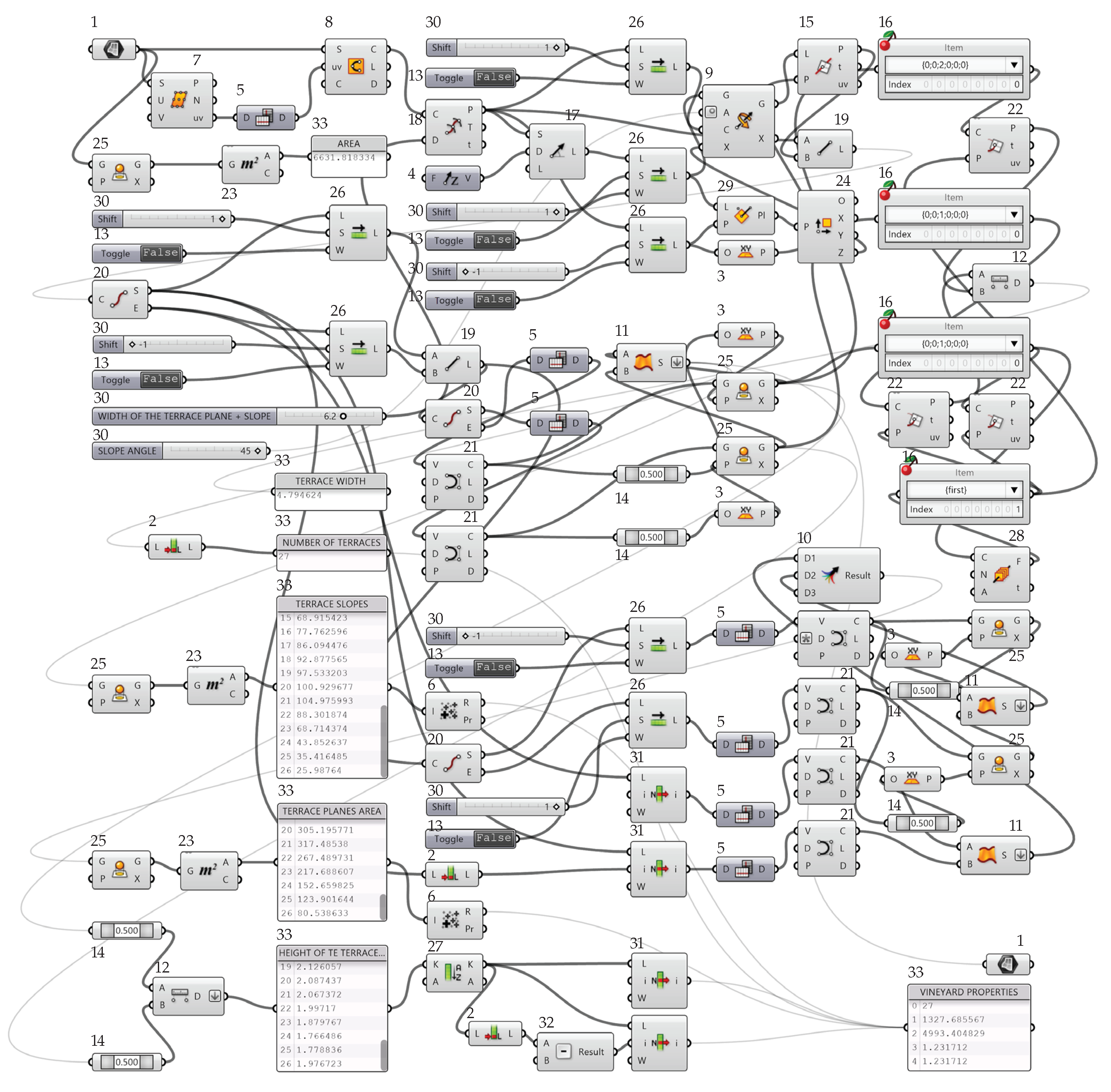
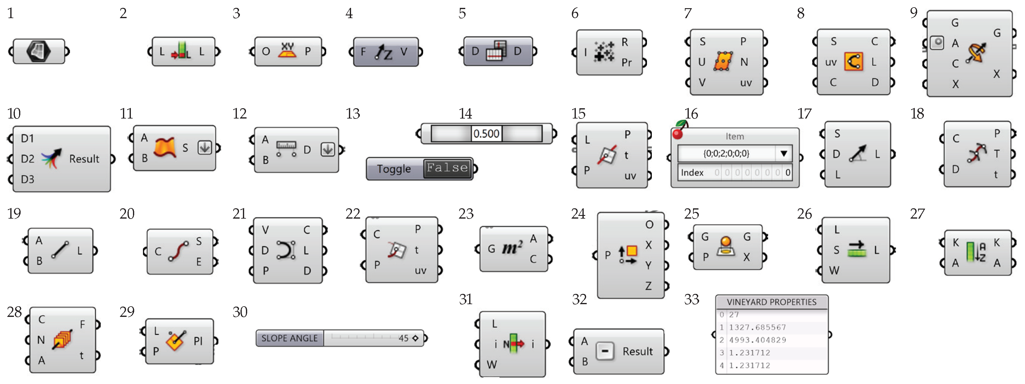
Illustration of the algorithm in Grasshopper that allows the combinatorial simulation of 3D terrace slope models by changing selected parameters. The individual components of the algorithm are: 1: surface parameter; 2: measure the length of a list; 3: world XY plane; 4: unit vector on {z} axis; 5: flip a matrix-like data tree; 6: perform mass addition; 7: divide surface; 8: create an interpolated curve on a surface; 9: rotate an object around a center point and an axis vector; 10: merge data streams; 11: create a surface between two curves; 12: compute Euclidean distance between two point coordinates; 13: Boolean (true/false) toggle; 14: evaluates a curve at a specific location; 15: solve intersection event for a line and a plane; 16: pick a single item from a data tree; 17: create a line segment defined by a start point, tangent, and length; 18: create an interpolated curve through a set of points; 19: create a line between two points; 20: represents a collection of 3D point coordinates; 21: represents a collection of 3D point coordinates; 22: solve intersection events for a curve and a plane; 23: solve area properties; 24: deconstruct a plane into its component parts; 25: project an object onto a plane; 26: offset all items in a list; 27: sort a list of numeric keys; 28: planes are defined by an origin point and three-axis vectors; 29: create a plane from a line and a point; 30: the setting of individual numeric values; 31: retrieve a specific item from a list; 32: subtraction command; and 33: text panel.
Figure 5.
Illustration of the algorithm in Grasshopper that allows the combinatorial simulation of 3D terrace slope models by changing selected parameters. The individual components of the algorithm are: 1: surface parameter; 2: measure the length of a list; 3: world XY plane; 4: unit vector on {z} axis; 5: flip a matrix-like data tree; 6: perform mass addition; 7: divide surface; 8: create an interpolated curve on a surface; 9: rotate an object around a center point and an axis vector; 10: merge data streams; 11: create a surface between two curves; 12: compute Euclidean distance between two point coordinates; 13: Boolean (true/false) toggle; 14: evaluates a curve at a specific location; 15: solve intersection event for a line and a plane; 16: pick a single item from a data tree; 17: create a line segment defined by a start point, tangent, and length; 18: create an interpolated curve through a set of points; 19: create a line between two points; 20: represents a collection of 3D point coordinates; 21: represents a collection of 3D point coordinates; 22: solve intersection events for a curve and a plane; 23: solve area properties; 24: deconstruct a plane into its component parts; 25: project an object onto a plane; 26: offset all items in a list; 27: sort a list of numeric keys; 28: planes are defined by an origin point and three-axis vectors; 29: create a plane from a line and a point; 30: the setting of individual numeric values; 31: retrieve a specific item from a list; 32: subtraction command; and 33: text panel.


Figure 6.
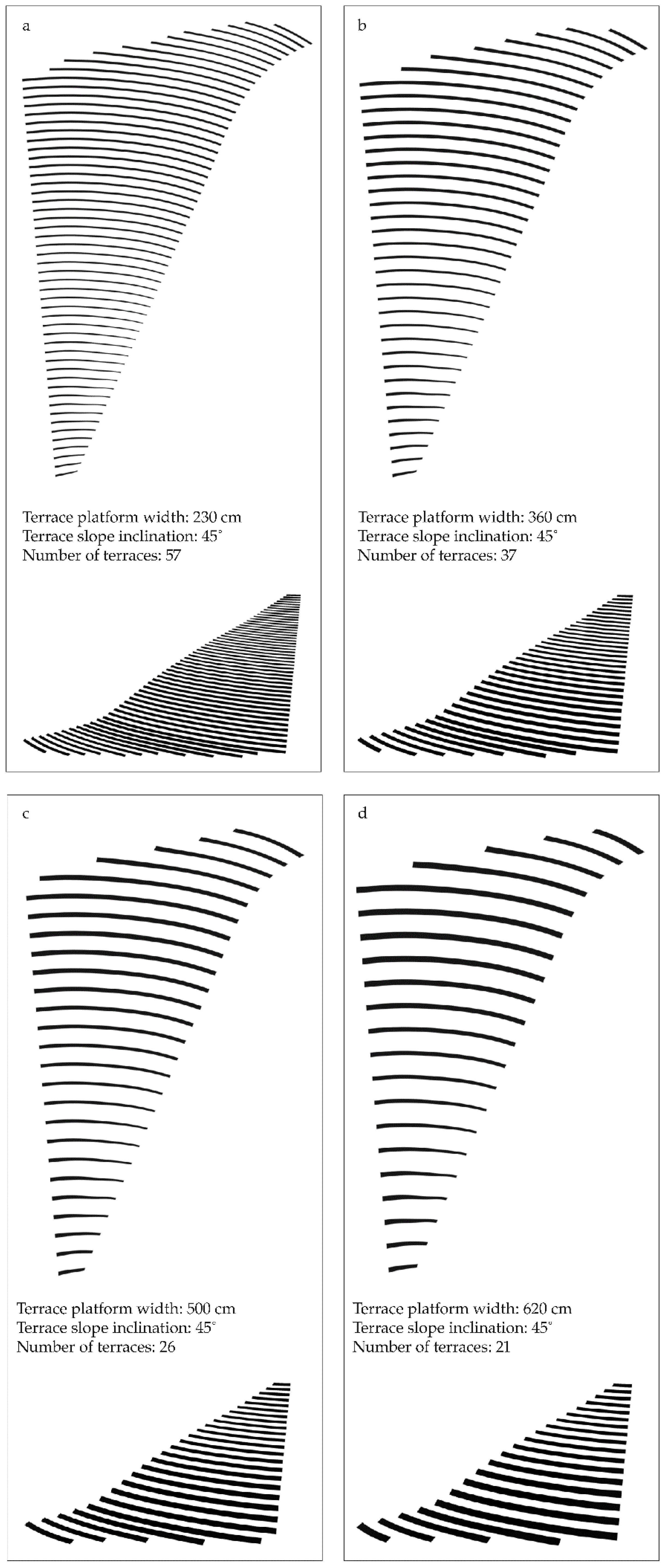
Terraced plot models generated in Grasshopper with selected parameters: plan (figure top) and 3D view (figure bottom). (a) Model of the terraced slope with 57 single-row terraces with terrace platforms 230 cm wide. (b) Model of the terraced slope with 37 double-row terraces with terrace platforms 360 cm wide. (c) Model of the terraced slope with 26 multi-row terraces with terrace platforms 500 cm wide. (d) Model of the terraced slope with 21 multi-row terraces with terrace platforms 620 cm wide.
Figure 6.
Terraced plot models generated in Grasshopper with selected parameters: plan (figure top) and 3D view (figure bottom). (a) Model of the terraced slope with 57 single-row terraces with terrace platforms 230 cm wide. (b) Model of the terraced slope with 37 double-row terraces with terrace platforms 360 cm wide. (c) Model of the terraced slope with 26 multi-row terraces with terrace platforms 500 cm wide. (d) Model of the terraced slope with 21 multi-row terraces with terrace platforms 620 cm wide.


Table 1.
Results of the combinatory parametric simulation of the terraced slope of the pilot area in Medana, Goriška Brda, Slovenia.
Table 1.
Results of the combinatory parametric simulation of the terraced slope of the pilot area in Medana, Goriška Brda, Slovenia.
| Terrace Type | Platform Width (m) | Platform and Slope Width (m) | Slope Inclination (°) | Number of Terraces | Slope Plan Area (m2) | Platform Plan Area (m2) | Minimum Height of Slopes (m) | Maximum Height of Slopes (m) | Usage Index (Tx) |
|---|---|---|---|---|---|---|---|---|---|
| Single-row | 2.3 | 2.3 | 90 | 72 | 0.00 | 6472 | 0.33 | 0.66 | 0.98 |
| 2.3 | 2.7 | 66 | 63 | 876 | 5600 | 0.45 | 0.84 | 0.84 | |
| 2.3 | 3 | 45 | 57 | 1347 | 5118 | 0.60 | 1.34 | 0.77 | |
| 2.7 | 2.7 | 90 | 61 | 0 | 6466 | 0.39 | 0.74 | 0.98 | |
| 2.7 | 3.2 | 66 | 53 | 877 | 5595 | 0.53 | 0.96 | 0.84 | |
| 2.7 | 3.5 | 45 | 49 | 1342 | 5094 | 0.70 | 1.33 | 0.77 | |
| Double-row | 3 | 3 | 90 | 55 | 0 | 6447 | 0.44 | 0.81 | 0.97 |
| 3 | 3.6 | 66 | 47 | 872 | 5558 | 0.60 | 1.06 | 0.84 | |
| 3 | 3.9 | 45 | 44 | 1339 | 5076 | 0.78 | 1.48 | 0.77 | |
| 3.6 | 3.6 | 90 | 46 | 0 | 6421 | 0.52 | 0.95 | 0.97 | |
| 3.6 | 4.2 | 66 | 40 | 868 | 5525 | 0.70 | 1.22 | 0.83 | |
| 3.6 | 4.6 | 45 | 37 | 1342 | 5068 | 0.91 | 1.67 | 0.76 | |
| Multi-row | 5 | 5 | 90 | 33 | 0 | 6364 | 0.72 | 1.24 | 0.96 |
| 5 | 5.9 | 66 | 29 | 870 | 5490 | 0.99 | 1.82 | 0.83 | |
| 5 | 6.4 | 45 | 26 | 1332 | 5001 | 1.27 | 2.20 | 0.75 | |
| 6.2 | 6.2 | 90 | 27 | 0 | 6321 | 0.87 | 1.50 | 0.95 | |
| 6.2 | 7.4 | 66 | 23 | 867 | 5436 | 1.24 | 2.18 | 0.82 | |
| 6.2 | 8.1 | 45 | 21 | 1341 | 4983 | 1.61 | 2.78 | 0.75 |
Table 2.
List of parameters of the variants on the pilot terraced slope in Medana, Gorizia Hills, Slovenia in 2006. V1: The version with straight terraces, where the plot was not fully utilized. V2: The alternative with curved terraces, where the terraces are better adapted to the terrain. V3: The version is a combination of straight and curved terraces adapted to the slope and shape of the terrain.
| Version | Number of Terraces | Number of Double-Row Terraces | Number of Multi-Row Terraces | Terrace Platform Plan Area (m2) | Terrace Slope Plan Area (m2) | Total Slope Area (m2) | Usage Index (Tx) |
|---|---|---|---|---|---|---|---|
| V1 | 16 | 7 | 9 | 4978 | 1278 | 6632 | 0.75 |
| V2 | 17 | 10 | 7 | 4638 | 1506 | 6632 | 0.70 |
| V3 | 18 | 7 | 10 | 4863 | 1678 | 6632 | 0.73 |
© 2020 by the authors. Licensee MDPI, Basel, Switzerland. This article is an open access article distributed under the terms and conditions of the Creative Commons Attribution (CC BY) license (http://creativecommons.org/licenses/by/4.0/).
Share and Cite
MDPI and ACS Style
Berčič, T.; Ažman-Momirski, L. Parametric Terracing as Optimization of Controlled Slope Intervention. Water 2020, 12, 634. https://doi.org/10.3390/w12030634
AMA Style
Berčič T, Ažman-Momirski L. Parametric Terracing as Optimization of Controlled Slope Intervention. Water. 2020; 12(3):634. https://doi.org/10.3390/w12030634
Chicago/Turabian StyleBerčič, Tomaž, and Lucija Ažman-Momirski. 2020. "Parametric Terracing as Optimization of Controlled Slope Intervention" Water 12, no. 3: 634. https://doi.org/10.3390/w12030634
Note that from the first issue of 2016, this journal uses article numbers instead of page numbers. See further details here.