Article

Electrospun Nylon 6,6/ZIF-8 Nanofiber Membrane for Produced Water Filtration

by
Nur Syakinah Abd Halim
1,
Mohd Dzul Hakim Wirzal
1,*,
Muhammad Roil Bilad
1,
Nik Abdul Hadi Md Nordin
1,
Zulfan Adi Putra
1,
Abdull Rahim Mohd Yusoff
2,
Thanitporn Narkkun
3 and
Kajornsak Faungnawakij
3
1
Chemical Engineering Department, Universiti Teknologi PETRONAS, Seri Iskandar 32610, Malaysia
2
Faculty of Science, Universiti Teknologi Malaysia, Skudai 81310, Malaysia
3
National Nanotechnology Center (NANOTEC), National Science and Technology Development Agency (NSTDA), 111 Thailand Science Park, Pathum Thani 12120, Thailand
*
Author to whom correspondence should be addressed.
Water 2019, 11(10), 2111; https://doi.org/10.3390/w11102111
Submission received: 1 August 2019 / Revised: 24 August 2019 / Accepted: 28 August 2019 / Published: 11 October 2019
(This article belongs to the Special Issue Advances in Water and Wastewater Monitoring and Treatment Technology)

Abstract

:
This study develops electrospun nylon 6,6 nanofiber membrane (NFM), incorporating zeolitic imidazolate framework-8 (ZIF-8) as the additive for produced water (PW) filtration. Electrospun NFM is suitable to be used as a filter, especially for water treatment, since it has a huge surface area to volume ratio, high porosity, and great permeability compared to the conventional membranes. These properties also enhance its competitiveness to be used as reverse osmosis pre-treatment, as the final stage of PW treatment water reuse purpose. However, the fouling issue and low mechanical strength of NFM reduces hydraulic performance over time. Therefore, this study employs ZIF-8 as an additive to improve nylon 6,6 NFM properties to reduce fouling and increase membrane tensile strength. Results show that the optimum loading of ZIF-8 was at 0.2%. This loading gives the highest oil rejection (89%), highest steady-state pure water permeability (1967 L/(m2·h·bar)), 2× higher than untreated nylon 6,6 NFM with tensile strength 5× greater (3743 MPa), and a steady-state permeability of 1667 L/(m2·h·bar) for filtration of real produced water.

1. Introduction

Produced water (PW) is a major contributor of waste stream in the oil and gas exploration and production process. Because of excessive discharge of poorly treated PW, marine ecosystems face great damage. This is worsened by the accidental spills of crude oil and refined petroleum products into the sea [1,2,3]. Several conventional methods have been implemented for treating PW, including coagulation/flocculation, adsorption, hydrocyclone, and floatation [4]. All of them have merits and shortcomings, particularly in removing small droplets of oil larger than 10 µm in size. PW can be treated further via reverse osmosis-based desalination for reused water purposes.
Membrane technology is one of the most reliable and effective remedies for wastewater. It requires a small footprint and gives stable quality of effluent. Nevertheless, fouling is one of the serious threats that decreases flux over time and membrane efficiency [5]. Fouling occurs due to deposition of particles at the top of membrane surfaces or inside membrane pores. This will increase the membrane replacement and backwashing costs while at the same time reduce the system productivity [6,7,8].
To address this issue, electrospun nanofiber membrane (NFM) has great potential to be used as a filter since it is found to be a more effective approach to reduce fouling [9]. Electrospun NFM is suitable to be applied in water treatment since it can handle the fouling problem better, has high porosity, and great surface area to volume ratio [10,11]. Usually, NFM is used for pre-treatment before nanofiltration or reverse osmosis processes [12]. Nylon 6,6 is also attractive to be used in the pre-treatment stage for removal of oils and particulate organics when aiming to reuse the treated PW. However, electrospun NFMs have poor mechanical strength because of random orientation within fibers, and have large distribution of fiber diameter [13,14].
Fortunately, the issues of fouling and low mechanical strength can be solved by applying material and surface modification such as blending. Numerous inorganic fillers such as silicon oxide [15], graphene oxide [16], and metal organic frameworks (MOFs) [17] have been introduced as additives to polymeric membranes for better separation performance. Various research has proven that MOFs is a potential filler for membrane separation due to its high compatibility with polyamide chain and porous structure [18,19]. Zeolitic imidazolate framework-8 (ZIF-8), which is one of the most significant parts of MOFs, would be a perfect filler to improve membrane separation as it has huge surface area, high adsorption capacity, and great chemical stability [20,21,22]. For example, Dai et al. [23] improved the properties of poly(lactic acid) (PLA) NFM by incorporating ZIF-8 as the additives for oily wastewater treatment. The resulting PLA/ZIF-8 membrane with 0.5 wt% ZIF-8 had tensile strength of 5.02 MPa, 1.81× higher, and all oil droplets ranging from 2–15 µm able to be removed, as it gave clearer filtrate compared to the pure PLA membrane. Furthermore, Ibrahim et al. [5] reported on the fabrication of polyvinylidene fluoride membranes incorporated with ZIF-8. It was found that at 8% loading of ZIF-8, highest permeability of pure water (150 L/(m2·h·bar)) and wastewater (94 L/(m2·h·bar)) were able to be achieved. The resulting membrane was also able to achieve an 87% reduction rate compared to the pure polyvinylidene fluoride membrane, which was about only 36%.
In the present study, we employ nylon 6,6 for fabrication of electrospun NFM. It has great hydrophilicity, good tensile strength, is very stable in nature, and has a high melting point which causes it to have great resistance to fouling, heat, and friction [24]. ZIF-8 has been introduced as the inorganic additive. It is expected that by blending ZIF-8 in nylon 6,6 solution, water permeability can be enhanced since ZIF-8 is able to control the swelling phenomena in NFM water filtration due to its hydrophobic nature. It will also improve electrospun NFM fouling resistance for real PW treatment.

2. Materials and Methods

2.1. Materials

The materials used were 2-Methyllimidazole, 2-MeIM (99%, Sigma Aldrich, St. Louis, MO, USA), trimethylamine (>99%, Sigma Aldrich), formic acid (98–100%, MERCK, Kenilworth, NJ, USA), glacial acetic acid (99.85%, VWR Chemicals, Radnor, PA, USA), zinc nitrate hexahydrate, Zn (NO3)2·6H2O (98%, Sigma Aldrich, St. Louis, MO, USA), and nylon 6,6 pellets (Sigma Aldrich). All were used as received without further purification.

2.2. Synthesis of ZIF-8

ZIF-8 was prepared with the ratio of Zn (NO3)2:2-MeIM:H2O 1:6:500. Two grams of Zn (NO3)2·6H2O was dissolved in 12.11 g of deionized water for preparation of metal salt solution. Ligand solution was prepared by dissolving 3.312 g of 2-MeIM into 48.45 g of deionized water, and 3.0 mL of trimethylamine was added subsequently. The metal salt solution was gradually added to the ligand solution until the solution became cloudy. The solution was then stirred vigorously for 30 minutes and the reaction product was centrifuged for several times. By using deionized water, the obtained product was washed several times to remove excess reactants. The product was dried in an oven at 60 °C for 12 hours, and was ground into fine particles before being dried in an oven again for a minimum of 12 hours at 100 °C [21].

2.3. Electrospinning of Nylon 6,6/ZIF-8 NFM

Nylon 6,6 pellets and a mixture of formic and acetic acid were used with a volume ratio of 14:86 respectively, in order to prepare the polymer solution. Different loadings of ZIF-8 powder (0.2 wt.%, 0.4 wt.%, 0.6 wt.%, 0.8 wt.%, and 1.0 wt.%) were added to the solvent mixture. Then, a 5 mL syringe was filled with the solution. The syringe was attached with a capillary tip of 0.8 mm inner diameter. The feeding rate was set at a fixed rate of 0.4 mL h−1. The voltage was set at 22.0 kV, and the distance from needle tip to a metal screen collector was set at 20 cm. The collector rotation was set at 500 RPM.

2.4. Membrane and Additive Characterization

The NFM was characterized based on surface morphology, viscosity of solution, crystallinity, porosity, hydrophilicity (contact angle), surface roughness, and mechanical strength, while for the additive it was measured based on surface morphology and crystallinity. Field emission scanning electron microscope (FESEM, Model: VPFESEM, Zeiss Supra55 VP, Feldbach, Switzerland) was used to observe the morphology of the membrane and ZIF-8 powder. As for the measurement for viscosity of the dope solution, viscosity meter (Brookfield CAP 2000+, Viscometer, Middleboro, MA, USA) was used. For measurement of membrane and additive crystallinity, powder X-ray diffractometer (XRD, Model: X’Pert3 Powder & Empyrean, PANalytical, Royston, UK) was used. For pore size measurement, Capillary Flow Porometry and ImageJ software were used. Furthermore, for porosity measurement, the dry wet method was implemented where the membrane weight and volume were measured. Membrane hydrophilicity was measured by using Interfacial Tension (IFT, Model: OCA 20, Data Pysics, Filderstadt, Germany). To analyze surface roughness, it was performed using an atomic force microscope (AFM, Model: NanoNavi E-Sweep, Anton Paar GmbH, Graz Austria). The mechanical strength of the membrane was tested according to ASTM standard D638 with crosshead speed 10 mm/min by using Universal Testing Machine (UTM, Shimadzu, Nakagyo-ku, Kyoto, Japan). The membranes were cut with a dimension of 30 mm × 70 mm and were mounted with aluminum plates at both ends for a better grip.

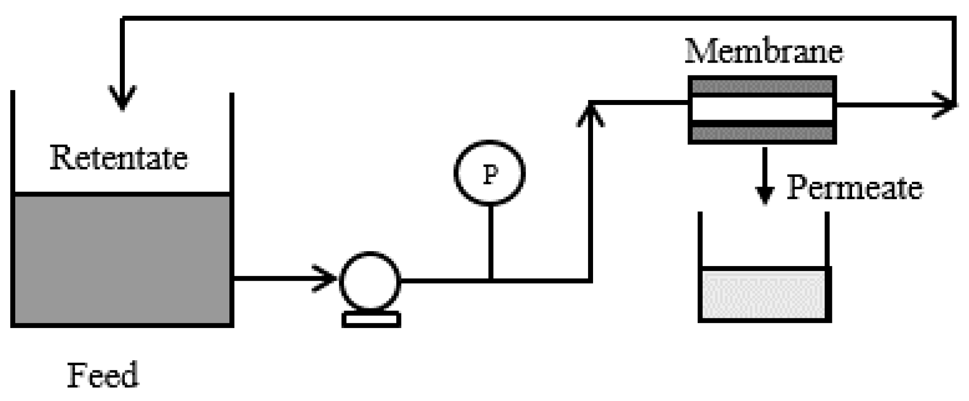
2.5. Permeability Analysis

Permeability of electrospun NFM for pure water and PW were measured by using cross-flow MF/UF testing units operated at constant feed pressure of 0.1 bar. The permeate was measured between 10-minute intervals until it reached a steady-state value. A NFM with an area of 9 cm2 was placed at the membrane holder while water was pumped from the feed tank. The feed liquid was pumped at a constant cross flow velocity of 0.44 cm/s. The set-up of cross-flow MF/UF Testing Unit can be seen at Figure 1.

2.6. Rejection Analysis

Some of the liquid samples were kept before and after filtration tests in order to conduct rejection analysis. Rejection analysis was divided under several tests: Rejection of oil, total organic carbon (TOC), and turbidity. They were measured using UV-VIS Spectrophotometer (Model: DR 5000 Spectrophotometer, Hach Company, Loveland, CO, USA), TOC analyzer (Model: TOC-VCSH, Shimadzu, Kyoto, Japan), and turbidity meter (Model: 2100Q Portable Turbidimeter, Hach Company, Loveland, CO, USA), respectively.

3. Results and Discussion

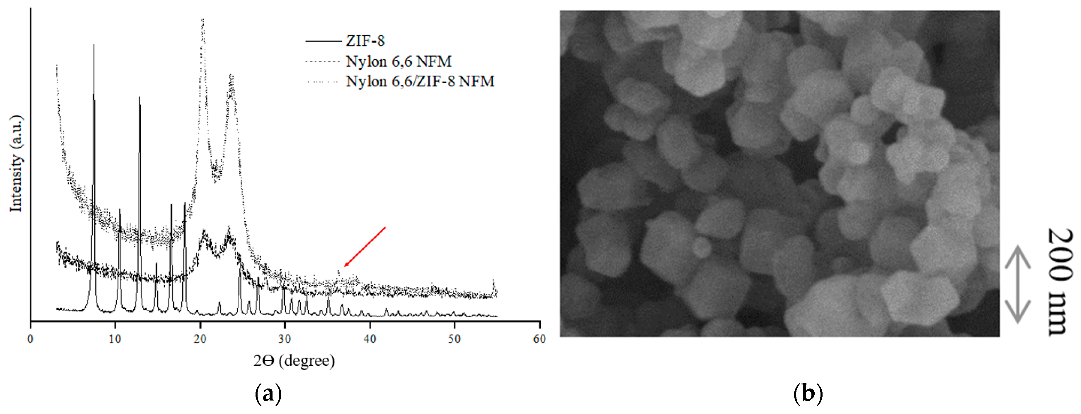
3.1. ZIF-8 Characterization

Figure 2a represents the XRD pattern of the synthesized ZIF-8. It shows that the synthesized ZIF-8 has sharp peaks, especially at 2θ of 7.40°, indicating good crystallinity and purity as also found in the literature [25], proving the sodalite structure of typical ZIF-8 nanoparticles. The morphology of the nanoparticles is shown in Figure 2b. The synthesized ZIF-8 has rhombic dodecahedron morphology with sizes around 140 nm, corresponding with the literature [19,26] as most of the particles show significant facets and sharp edges and corners.

3.2. Membrane Crystallization

The XRD patterns of nylon 6,6 NFM and nylon 6,6/ZIF-8 NFM are shown in Figure 2a. The XRD pattern of nylon 6,6 is in good agreement with the literature and had two peaks at 2ϴ of 20° and 23° which were called as phase α (alpha) and related with the formation of a crystalline polyamide phase [27]. Nylon 6,6/ZIF-8 NFM shows more characteristics of nylon 6,6 since both are amorphous. However, in the XRD pattern of nylon 6,6/ZIF-8 NFM, there was a stronger peak at 36° (see the red arrow in Figure 2a) which suggests that there is presence of ZIF-8 in the fiber. It is noted that the characteristic peaks of ZIF-8 in the membrane have low intensity; this might be due to low loading of ZIF-8 in the membrane, and also due to membrane amorphous structure which overpowers the membrane XRD pattern.

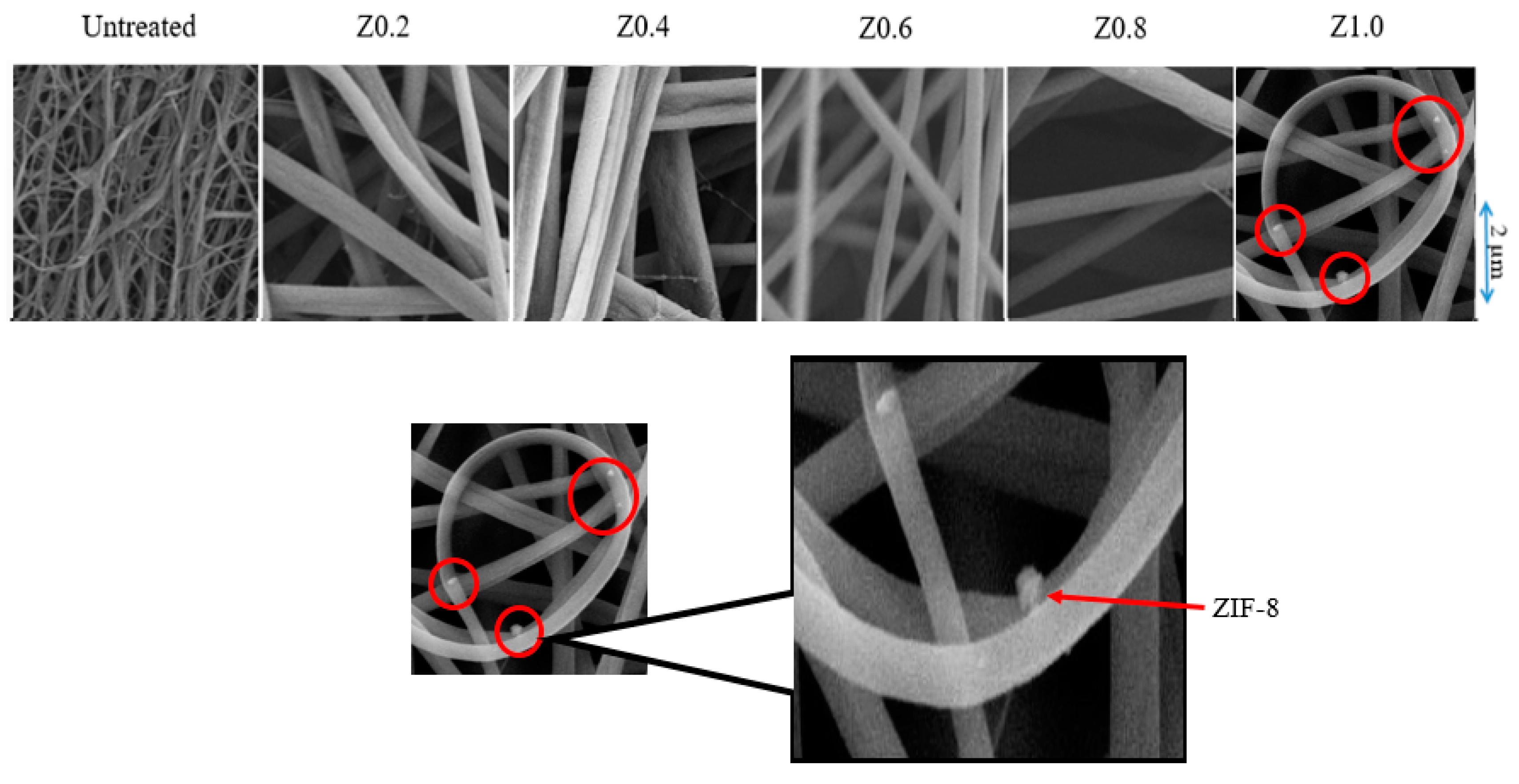
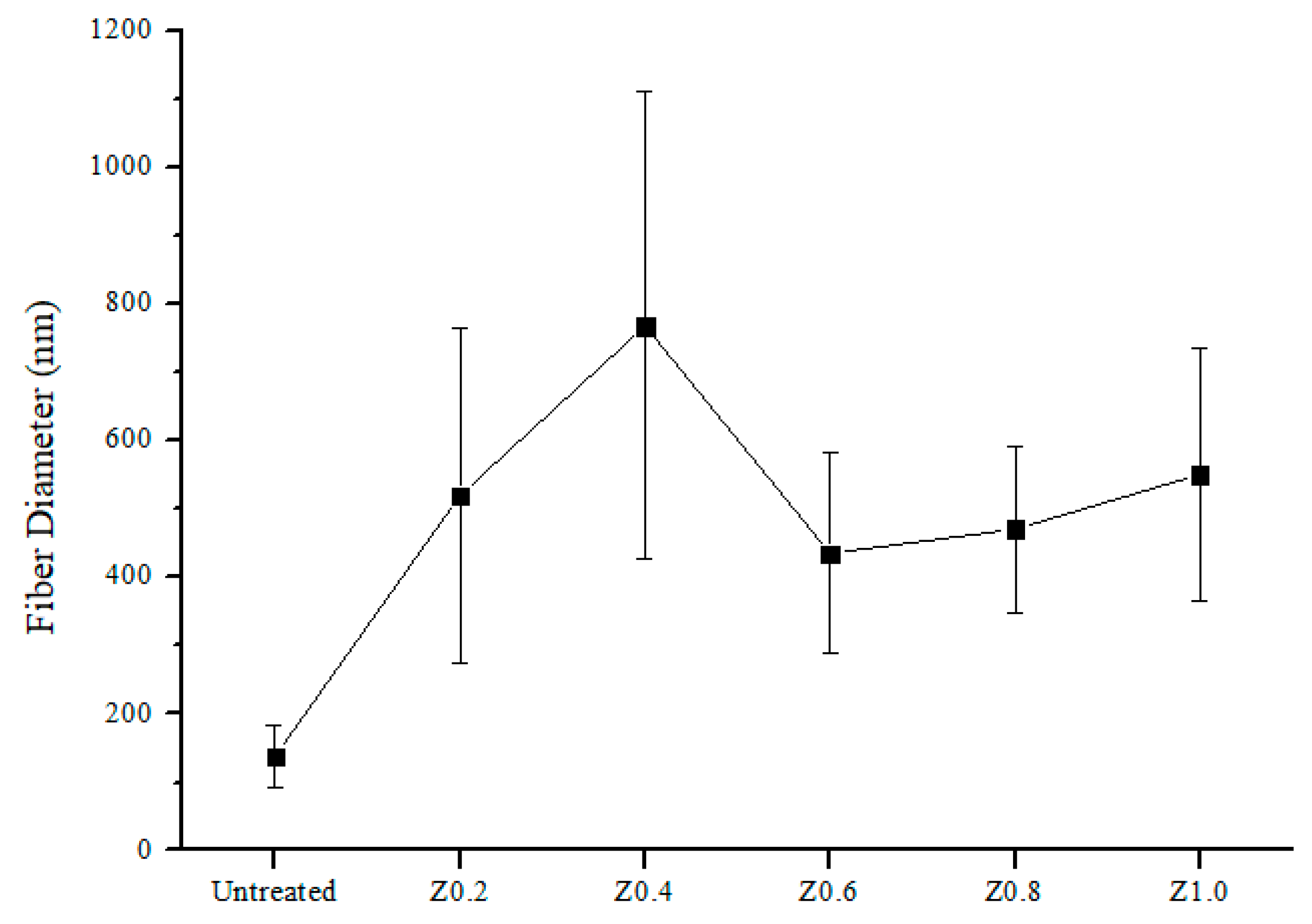
3.3. Surface Morphology and Fiber Diameter of Nylon 6,6/ZIF-8 NFM

The greater loading of the additives causes higher concentration/viscosity of the dope solution (Figure 3), resulting in a larger polymer jet and leading to deposition of fiber with a larger diameter [28]. Moreover, the increase in fiber diameter will produce a membrane with bigger pore size [29,30]. This could happen as there is incomplete drying of NFM due to higher viscosity of dope solution [31].
Figure 4 shows the FESEM images of the plain and electrospun nylon 6, 6/ ZIF-8 NFM. The morphology of nylon 6,6/ZIF-8 NFM shows notable changes in comparison with the untreated NFM. From the figure, it can be observed that at Z1.0 NFM, ZIF-8 nanoparticles have been embedded onto the membrane due to polymer-filler interface (see the red circles). Moreover, the fiber diameter started to increase up till 800 nm (Figure 5) as the weight percentage of ZIF-8 increased from 0.2% to 0.4%. This trend suggests that the addition of ZIF-8 changes the concentration of the dope solution.
However, as the loading was set to 0.6%, the membrane fiber diameter reduced to 400 nm. This is due to the absorption of solvent by the porous ZIF-8 nanoparticles. This causes slower evaporation of solvent, hence producing fibers with smaller diameters [23]. From here, it can be concluded that at 0.6% loading of ZIF-8, fiber diameter is the lowest, and by having smaller fiber diameter it will increase the membrane surface area.

3.4. Membrane Porosity and Surface Roughness

The porosity of NFM increased with the increase of ZIF-8 loading (Table 1). This is most probably due to its pore size. Bigger pore size will allow more water uptake. As mentioned before, the increment in membrane pore size is due to increase in membrane diameter. Furthermore, the surface roughness of the membrane increases as the loading of ZIF-8 increases (Table 1) due to the presence of ZIF-8 particles, as also reported by others [23].

3.5. Contact Angle

Figure 6 shows water contact angle vs. time for untreated nylon 6,6 NFM and nylon 6,6 NFM incorporated with ZIF-8. It was observed that the hydrophilicity of NFM decreases as the loading of ZIF-8 increases. This is due to the hydrophobic nature of ZIF-8 [32] which hinders the water uptake. Apart from that, decrease in membrane hydrophilicity is also associated with the surface roughness. Rougher surface leads to lower interface energy due to a greater interfacial contact area between liquid and solid and hence increases the water contact angle [33,34]. Nevertheless, even though the water contact angle increases, it is still below 90°, which indicates that all of the membranes are hydrophilic.

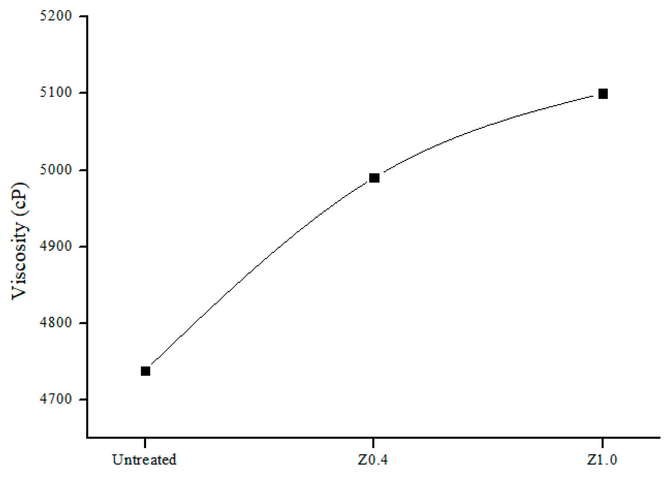
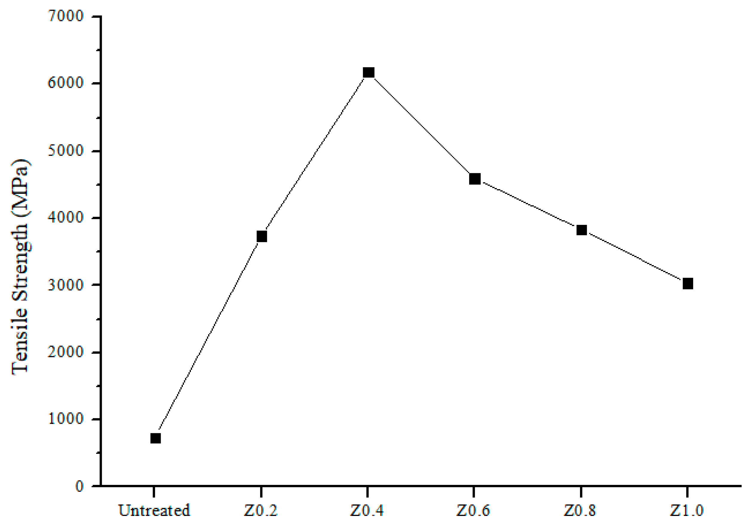
3.6. Mechanical Properties of Nylon 6,6/ZIF-8 NFM

Figure 7 shows the graph of tensile strength between the untreated NFM and nylon 6,6 NFM/ZIF-8. As observed, the tensile strength of the NFM increases as the loading of ZIF-8 increases. Significant increment of tensile strength was observed at 0.4% loading of ZIF-8, 8× higher (6180 MPa) than the untreated nylon 6,6 NFM (738 MPa). The increment in tensile strength indicates that ZIF-8 and nylon 6,6 matrix have strongly interacted with each other [21,35].
Further, increasing the ZIF-8 loading beyond 0.4% decreases the tensile strength of NFM. This can be explained by the weak interfacial adhesion phenomena, which might be due to particle aggregation. It is very important to have strong interfacial adhesion in order for effective stress transfer to occur so that high composite strength of the membrane will be achieved [36,37]. From this, it can be concluded that 0.4% is the optimum ZIF-8 loading to achieve the highest tensile strength for nylon 6,6 based NFM.

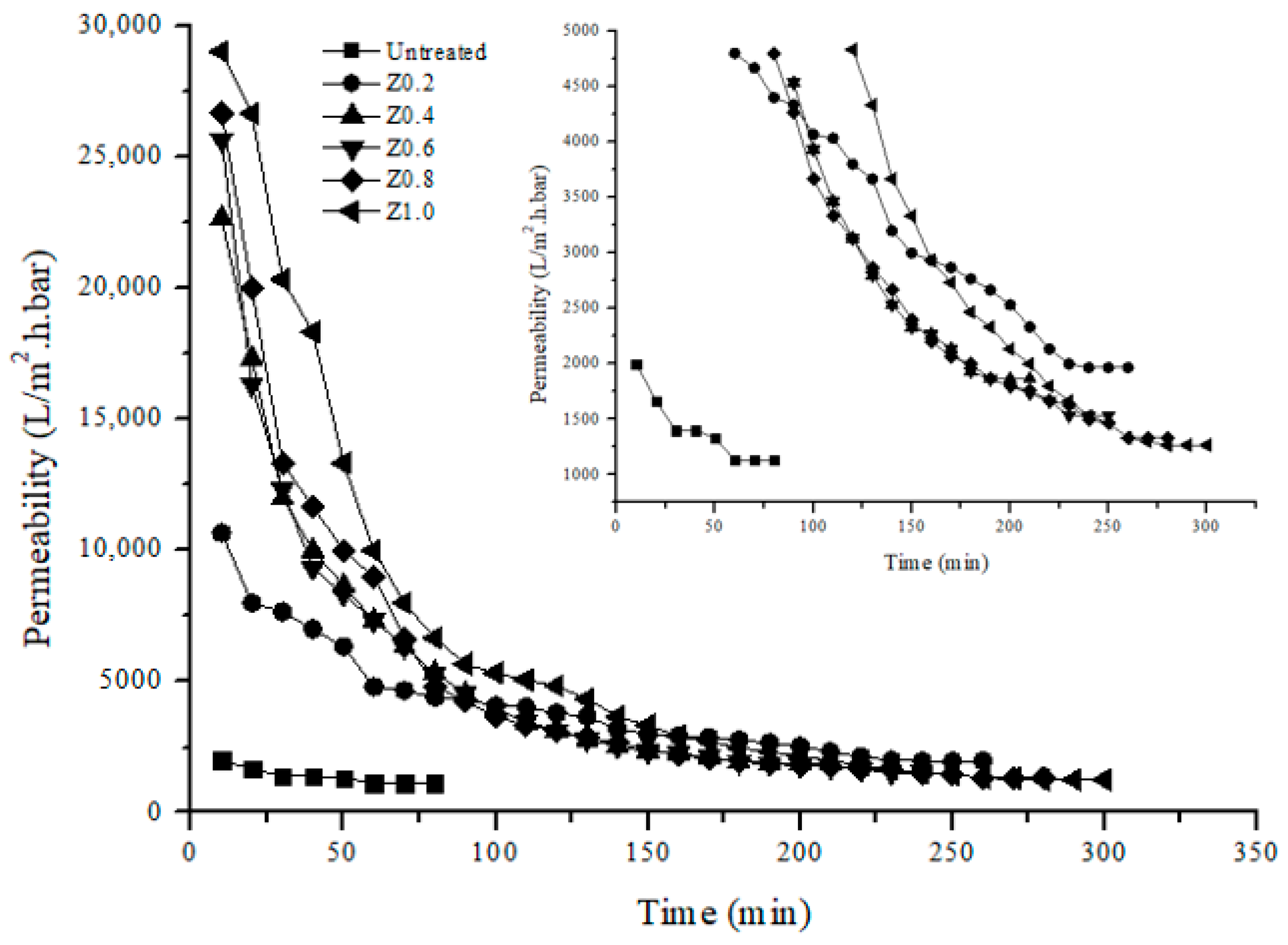
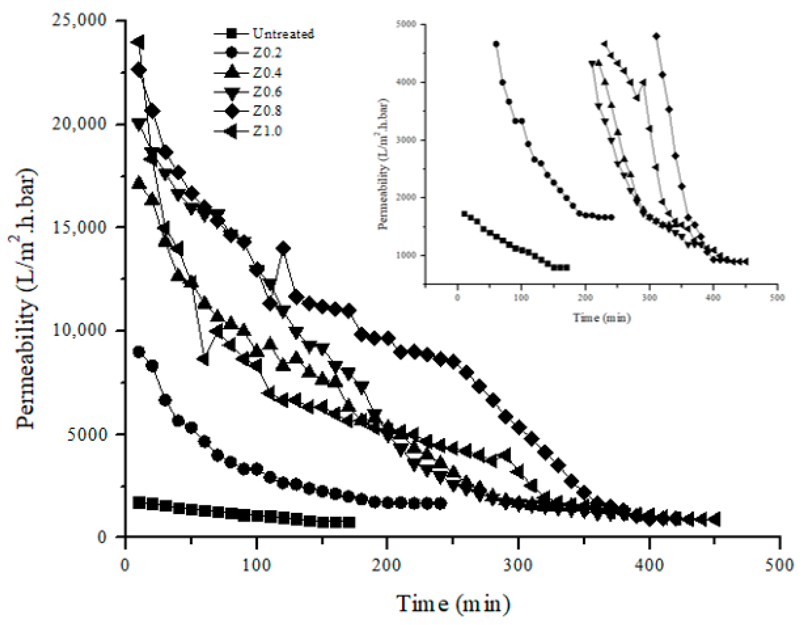
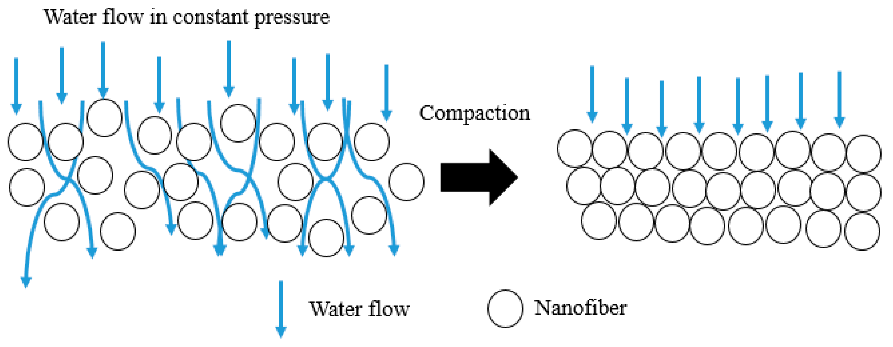
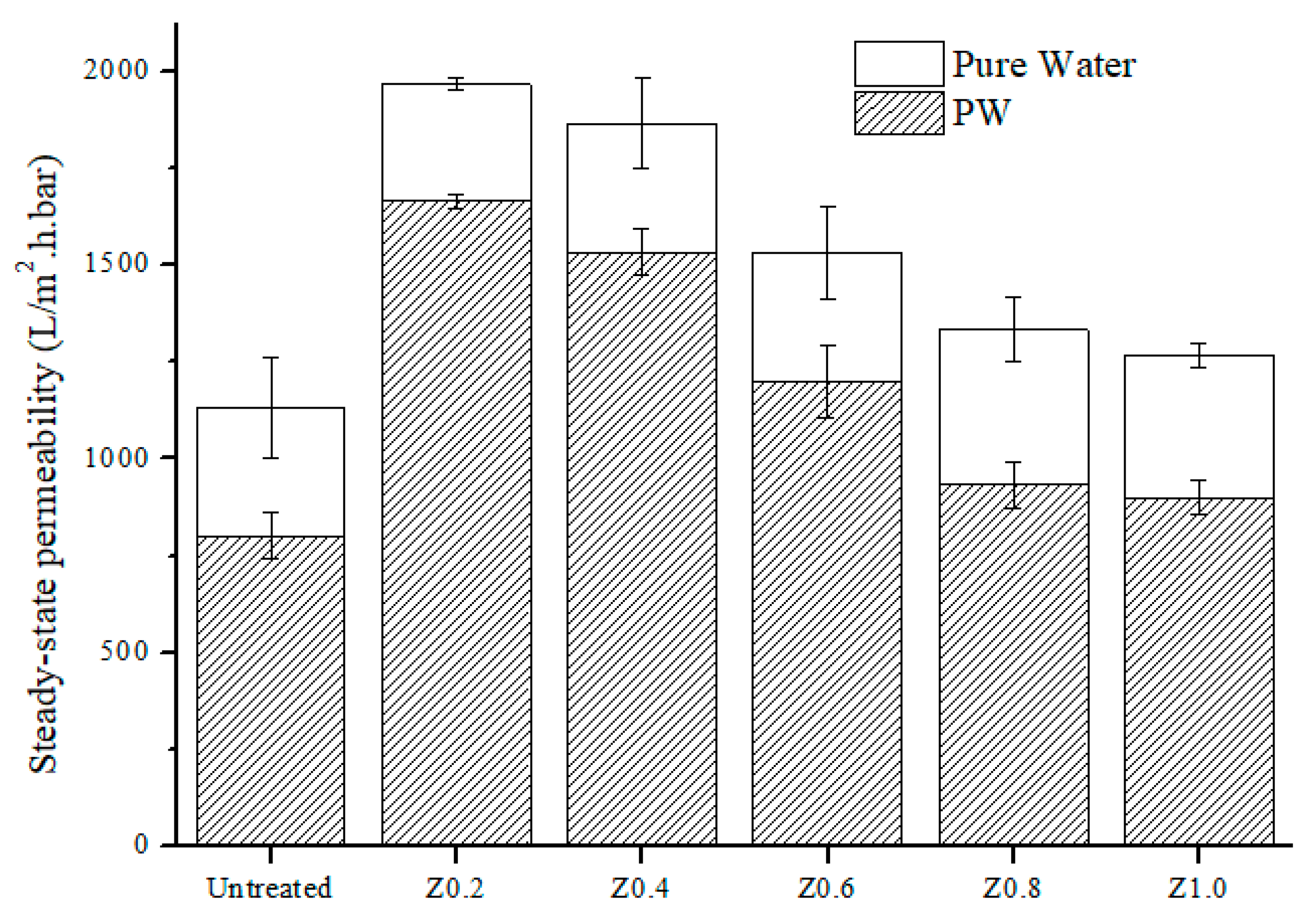
3.7. Permeability Analysis

Figure 8 shows that the addition of ZIF-8 greatly increases the initial permeability of pure water which correlates with the pore size and porosity data in Table 1. The presence of ZIF-8 as a hydrophobic additive promotes the “deswelling effect” as the membrane pores are retained at their size, allowing more liquid to pass through without absorbing too much water, thus reducing membrane swelling. Usually, hydrophilic materials swell in water as water forms physical interactions with the material [38]. Due to this reason, the superhydrophilic membrane is sometimes not preferable to be used since it has greater water uptake, and therefore greater swelling effect. Swelling enlarges the fiber and eventually reduces the membrane pore size and water permeability [39]. Due to this phenomena, hydrophobic additive is preferred in this study in order to control the swelling effect.
However, the permeability decreasing with time may be due to compression of the pores under the pressure. As time goes by, the “deswelling effect” slows down due to fouling, as can be seen in Figure 9 where at 1.0% loading of ZIF-8, it faces sharp decline due to higher hydrophobicity than other membranes. The hydrophobic nature of ZIF-8 favors more adsorption of oil, which then causes the oil to be accumulated and eventually blocks the membrane pores. Other than that, NFM membranes incorporated with ZIF-8 took a longer time to get fouled, where at Z1.0 NFM (Figure 9), the longest it took was about 6 hours. This is because the greater water uptake at the initial permeability and harder structure causes the membrane to take more time to achieve steady-state. Moreover, Figure 10 illustrates the membrane compaction process, which explains the reason for the membrane taking a longer time to achieve steady-state in PW treatment. Due to fouling phenomena, treatment for PW took a longer time compared to pure water. Normally, the water will flow freely through the pores until the membrane becomes compact, hence achieving a steady- state condition. However, as the feed changes into PW, the formation of cake layer on top of the membrane surface will block the pores. This will then delay the membrane compaction process since water will take more time to flow through the membrane, as there is not much presence of pores. The increase in membrane resistance prolongs the time taken for the membrane to achieve steady-state, as the cake layer needs to be compact along with the membrane. In addition, the highest steady-state permeability of 1967 L/(m2·h·bar)was observed at Z0.2 NFM (Figure 11) for pure water, and 1667 L/(m2·h·bar) for PW which are 2× higher than the untreated nylon 6,6 NFM.

3.8. Rejection Analysis

From the rejection analysis shown in Table 2, nylon 6,6 NFM incorporated with ZIF-8 gave more than 80% rejection of oil and excellent suspended solid removal shown from turbidity data. Due to its large pore size, NFM incorporated with ZIF-8 was unable to achieve 100% rejection, as some oil droplets smaller than 0.86 µm were able to pass through the membrane pores. Z0.2 NFM has the highest rejection at 89% with oil concentration below 10 ppm, which is able to meet the Malaysia standard B discharge requirement. This is due to its smaller pore size and lower hydrophobicity compared to the other membranes, so less oil molecules can absorb and pass through the membrane. Nevertheless, increasing the loading of ZIF-8 will decrease the selectivity of the membrane. This can relate to the “deswelling effect” where at higher loading of ZIF-8, the pore size of the membrane is maintained at its size, allowing more liquid to penetrate through the membrane. Moreover, there no significant changes could be observed at TOC data. This is because the properties of NFM, which are similar to MF membrane, enables it to only filter large colloids or in this study, dispersed oil inside PW. From here, it can be concluded that NFM is suitable to act as a pre-treatment for PW. Based on both permeability and rejection analysis, it shows that NFM is able to reduce the fouling issue, and can act as a pre-treatment for nanofiltration, reverse osmosis, or forward osmosis process. From here, operational costs can be reduced since bigger particles are able to be removed from PW which make them easier to be cleaned and operated [7].

4. Conclusions

The effect of blending on the surface properties and performance of electrospun nylon 6,6 NFM for pre-treatment of PW were studied and compared. It is found that the presence of ZIF-8 nanoparticles enlarges fiber diameter and the water permeability due to the deswelling effect. The highest steady-state pure water permeability was found at Z0.2 NFM, two times higher (1967 L/(m2·h·bar)) than untreated nylon 6,6 NFM and took a longer time to get fouled (about 220 min), compared to untreated nylon 6,6 NFM (about 160 min). Z0.2 membrane also has the highest oil rejection (89%) with 5× higher in tensile strength (3743 MPa).

Author Contributions

Conceptualization, M.D.H.W., N.A.H.M.N., and M.R.B.; methodology, N.A.H.M.N. and M.R.B.; validation, M.D.H.W., and M.R.B.; formal analysis, Z.A.P.; investigation, N.S.A.H.; resources, A.R.M.Y. and M.D.H.W.; data curation, M.R.B. and M.D.H.W.; writing—original draft preparation, N.S.A.H.; writing—review and editing, M.D.H.W., M.R.B., N.A.H.M.N., T.N., and K.F.; visualization, N.S.A.H.; supervision, M.D.H.W.; project administration, M.D.H.W.; funding acquisition, M.D.H.W.

Funding

This research was funded by Yayasan Universiti Teknologi Petronas with grant number 0153AA-H29.

Acknowledgments

We would like to acknowledge Universiti Teknologi PETRONAS for providing facilities to conduct research activities.

Conflicts of Interest

The authors declare no conflict of interest.

References

  1. Bakke, T.; Klungsøyr, J.; Sanni, S. Environmental impacts of produced water and drilling waste discharges from the Norwegian offshore petroleum industry. Mar. Environ. Res. 2013, 92, 154–169. [Google Scholar] [CrossRef] [PubMed] [Green Version]
  2. Soto, L.V.; Botello, A.; Licea, S.; Lizárraga-Partida, M.; Yáñez-Arancibia, A. The environmental legacy of the Ixtoc-I oil spill in Campeche Sound, southwestern Gulf of Mexico. Front. Mar. Sci. 2014, 1, 1–9. [Google Scholar] [CrossRef]
  3. Zhang, C.; Li, P.; Cao, B. Electrospun Microfibrous Membranes Based on PIM-1/POSS with High Oil Wettability for Separation of Oil–Water Mixtures and Cleanup of Oil Soluble Contaminants. Ind. Eng. Chem. Res. 2015, 54, 8772–8781. [Google Scholar] [CrossRef]
  4. Su, Y.; Zhao, Q.; Liu, J.; Zhao, J.; Li, Y.; Jiang, Z. Improved oil/water emulsion separation performance of PVC/CPVC blend ultrafiltration membranes by fluorination treatment. Desalin. Water Treat. 2015, 55, 304–314. [Google Scholar] [CrossRef]
  5. Ibrahim, N.A.; Wirzal, M.D.H.; Nordin, N.A.H.; Halim, N.S.A. Development of Polyvinylidene fluoride (PVDF)-ZIF-8 Membrane for Wastewater Treatment. IOP Conf. Ser. Earth Environ. Sci. 2018, 140, 012021. [Google Scholar] [CrossRef]
  6. Benito, A.; Garcia, G.; Gonzalez-Olmos, R. Fouling reduction by UV-based pretreatment in hollow fiber ultrafiltration membrane for urban wastewater reuse. J. Membr. Sci. 2017, 536, 141–147. [Google Scholar] [CrossRef]
  7. Eliseus, A.; Bilad, M.R.; Nordin, N.A.H.M.; Putra, Z.A.; Wirzal, M.D.H. Tilted membrane panel: A new module concept to maximize the impact of air bubbles for membrane fouling control in microalgae harvesting. Bioresour. Technol. 2017, 241, 661–668. [Google Scholar] [CrossRef] [PubMed]
  8. Jepsen, K.L.; Bram, M.V.; Pedersen, S.; Yang, Z. Membrane Fouling for Produced Water Treatment: A Review Study from a Process Control Perspective. Water 2018, 10, 847. [Google Scholar] [CrossRef]
  9. Bilad, M.R.; Westbroek, P.; Vankelecom, I.F.J. Assessment and optimization of electrospun nanofiber-membranes in a membrane bioreactor (MBR). J. Membr. Sci. 2011, 380, 181–191. [Google Scholar] [CrossRef]
  10. Jiříček, T.; Komárek, M.; Lederer, T. Polyurethane Nanofiber Membranes for Waste Water Treatment by Membrane Distillation. J. Nanotechnol. 2017, 2017. [Google Scholar] [CrossRef]
  11. Homaeigohar, S.; Elbahri, M. An Amphiphilic, Graphitic Buckypaper Capturing Enzyme Biomolecules from Water. Water 2019, 11, 2. [Google Scholar] [CrossRef]
  12. Liu, C.; Li, X.; Liu, T.; Liu, Z.; Li, N.; Zhang, Y.; Xiao, C.; Feng, X. Microporous CA/PVDF membranes based on electrospun nanofibers with controlled crosslinking induced by solvent vapor. J. Membr. Sci. 2016, 512, 1–12. [Google Scholar] [CrossRef]
  13. Ahmadi, A.; Qanati, O.; Seyed Dorraji, M.S.; Rasoulifard, M.H.; Vatanpour, V. Investigation of antifouling performance a novel nanofibrous S-PVDF/PVDF and S-PVDF/PVDF/GO membranes against negatively charged oily foulants. J. Membr. Sci. 2017, 536, 86–97. [Google Scholar] [CrossRef]
  14. Huang, L.; Manickam, S.S.; McCutcheon, J.R. Increasing strength of electrospun nanofiber membranes for water filtration using solvent vapor. J. Membr. Sci. 2013, 436, 213–220. [Google Scholar] [CrossRef]
  15. Islam, M.S.; McCutcheon, J.R.; Rahaman, M.S. A high flux polyvinyl acetate-coated electrospun nylon 6/SiO2 composite microfiltration membrane for the separation of oil-in-water emulsion with improved antifouling performance. J. Membr. Sci. 2017, 537, 297–309. [Google Scholar] [CrossRef]
  16. Naseeb, N.; Mohammed, A.A.; Laoui, T.; Khan, Z. A Novel PAN-GO-SiO2 Hybrid Membrane for Separating Oil and Water from Emulsified Mixture. Materials 2019, 12, 212. [Google Scholar] [CrossRef] [PubMed]
  17. Yang, L.; Wang, Z.; Zhang, J. Zeolite imidazolate framework hybrid nanofiltration (NF) membranes with enhanced permselectivity for dye removal. J. Membr. Sci. 2017, 532, 76–86. [Google Scholar] [CrossRef]
  18. Basu, S.; Balakrishnan, M. Polyamide thin film composite membranes containing ZIF-8 for the separation of pharmaceutical compounds from aqueous streams. Sep. Purif. Technol. 2017, 179, 118–125. [Google Scholar] [CrossRef]
  19. Nordin, N.A.H.M.; Racha, S.M.; Matsuura, T.; Misdan, N.; Sani, N.A.A.; Ismail, A.F.; Mustafa, A. Facile modification of ZIF-8 mixed matrix membrane for CO2/CH4 separation: Synthesis and preparation. RSC Adv. 2015, 5, 43110–43120. [Google Scholar] [CrossRef]
  20. Nordin, N.A.H.M.; Ismail, A.F.; Mustafa, A. Synthesis and Preparation of Asymmetric PSf/ZIF-8 Mixed Matrix Membrane for CO2/CH4 Separation. J. Teknologi 2014, 69, 9. [Google Scholar] [CrossRef]
  21. Nordin, N.a.H.M.; Ismail, A.F.; Mustafa, A.; Murali, R.S.; Matsuura, T. The impact of ZIF-8 particle size and heat treatment on CO2/CH4 separation using asymmetric mixed matrix membrane. RSC Adv. 2014, 4, 52530–52541. [Google Scholar] [CrossRef]
  22. Hadi, A.; Karimi-Sabet, J.; Dastbaz, A. Parametric study on the mixed solvent synthesis of ZIF-8 nano- and micro-particles for CO adsorption: A response surface study. Front. Chem. Sci. Eng. 2019, 1–16. [Google Scholar] [CrossRef]
  23. Dai, X.; Cao, Y.; Shi, X.; Wang, X. The PLA/ZIF-8 Nanocomposite Membranes: The Diameter and Surface Roughness Adjustment by ZIF-8 Nanoparticles, High Wettability, Improved Mechanical Property, and Efficient Oil/Water Separation. Adv. Mater. Interfaces 2016, 3, 1–6. [Google Scholar] [CrossRef]
  24. Bilad, M.R.; Azizo, A.S.; Wirzal, M.D.H.; Jia Jia, L.; Putra, Z.A.; Nordin, N.A.H.M.; Mavukkandy, M.O.; Jasni, M.J.F.; Yusoff, A.R.M. Tackling membrane fouling in microalgae filtration using nylon 6,6 nanofiber membrane. J. Environ. Manag. 2018, 223, 23–28. [Google Scholar] [CrossRef] [PubMed]
  25. Jian, M.; Liu, B.; Zhang, G.; Liu, R.; Zhang, X. Adsorptive removal of arsenic from aqueous solution by zeolitic imidazolate framework-8 (ZIF-8) nanoparticles. Colloids Surf. A Physicochem. Eng. Asp. 2015, 465, 67–76. [Google Scholar] [CrossRef]
  26. Schejn, A.; Balan, L.; Falk, V.; Aranda, L.; Medjahdi, G.; Schneider, R. Controlling ZIF-8 nano- and microcrystal formation and reactivity through zinc salt variations. CrystEngComm 2014, 16, 4493–4500. [Google Scholar] [CrossRef]
  27. Araujo, E.; Leite, A.M.D.; Medeiros, V.D.N.; Paz, R.A.; Lira, H.D.L. Comparative Study of Membranes Obtained from PA6 and PA66/National Clay Nanocomposites. Adv. Nanocomposite Technol. 2011. [Google Scholar] [CrossRef] [Green Version]
  28. Zhong, Z.; Cao, Q.; Wang, X.; Wu, N.; Wang, Y. PVC–PMMA composite electrospun membranes as polymer electrolytes for polymer lithium-ion batteries. Ionics 2012, 18, 47–53. [Google Scholar] [CrossRef]
  29. Rnjak-Kovacina, J.; Weiss, A.S. Increasing the pore size of electrospun scaffolds. Tissue Eng. Part B Rev. 2011, 17, 365–372. [Google Scholar] [CrossRef]
  30. Širc, J.; Hobzová, R.; Kostina, N.; Munzarová, M.; Juklíčková, M.; Lhotka, M.; Kubinová, Š.; Zajícová, A.; Michálek, J. Morphological Characterization of Nanofibers: Methods and Application in Practice. J. Nanomater. 2012. [Google Scholar] [CrossRef]
  31. Pillay, V.; Dott, C.; Choonara, Y.E.; Tyagi, C.; Tomar, L.; Kumar, P.; du Toit, L.C.; Ndesendo, V.M.K. A Review of the Effect of Processing Variables on the Fabrication of Electrospun Nanofibers for Drug Delivery Applications. J. Nanomater. 2013. [Google Scholar] [CrossRef]
  32. Ortiz, A.U.; Freitas, A.P.; Boutin, A.; Fuchs, A.H.; Coudert, F.-X. What makes zeolitic imidazolateframeworks hydrophobic or hydrophilic? The impact of geometry and functionalization on water adsorption. Phys. Chem. Chem. Phys. 2014, 16, 9940–9949. [Google Scholar] [CrossRef] [PubMed]
  33. Nosonovsky, M.; Bhushan, B. Wetting of rough three-dimensional superhydrophobic surfaces. Microsyst. Technol. 2006, 12, 273–281. [Google Scholar] [CrossRef]
  34. Reshmi, C.R.; Suja, P.S.; Juraij, A.; Athiyanathil, S. Fabrication of superhydrophobic polycaprolactone/beeswax electrospun membranes for high-efficiency oil/water separation. RSC Adv. 2017, 7, 2092–2102. [Google Scholar] [Green Version]
  35. Gholami, M.; Mohammadi, T.; Mosleh, S.; Hemmati, M. CO2/CH4 separation using mixed matrix membrane-based polyurethane incorporated with ZIF-8 nanoparticles. Chem. Pap. 2017, 71, 1839–1853. [Google Scholar] [CrossRef]
  36. Fu, S.-Y.; Feng, X.-Q.; Lauke, B.; Mai, Y.-W. Effects of particle size, particle/matrix interface adhesion and particle loading on mechanical properties of particulate–polymer composites. Compos. Part B Eng. 2008, 39, 933–961. [Google Scholar] [CrossRef]
  37. Metın, D.; Tihminlioğlu, F.; Balköse, D.; Ülkü, S. The effect of interfacial interactions on the mechanical properties of polypropylene/natural zeolite composites. Compos. Part A Appl. Sci. Manuf. 2004, 35, 23–32. [Google Scholar] [CrossRef] [Green Version]
  38. Wang, Y.; Górecki, R.P.; Stamate, E.; Norrman, K.; Aili, D.; Zuo, M.; Guo, W.; Hélix-Nielsen, C.; Zhang, W. Preparation of super-hydrophilic polyphenylsulfone nanofiber membranes for water treatment. RSC Adv. 2018, 9, 278–286. [Google Scholar] [CrossRef]
  39. Lubasova, D.; Mullerova, J.; Netravali, A.N. Water-resistant plant protein-based nanofiber membranes. J. Appl. Polym. Sci. 2015, 132. [Google Scholar] [CrossRef]
Figure 1. Cross-flow filtration testing unit.
Water 11 02111 g001
Figure 2. (a) XRD patterns for zeolitic imidazolate framework -8 (ZIF-8) nanoparticles, nylon 6,6 nanofiber membrane, and nylon 6,6/ZIF-8 NFM; (b) SEM image showing morphology of ZIF-8.
Water 11 02111 g002
Figure 3. A plot of viscosity according to different loading of ZIF-8.
Water 11 02111 g003
Figure 4. FESEM images (magnification 5000×) of untreated nylon 6,6 and nylon 6,6/ZIF-8 NFM. The inset shows the presence of ZIF-8 on the structure of NFM.
Water 11 02111 g004
Figure 5. A plot of fiber diameter according to different loading of ZIF-8.
Water 11 02111 g005
Figure 6. Water contact angle for untreated nylon 6,6 NFM and nylon 6,6/ZIF-8 NFM.
Water 11 02111 g006
Figure 7. Tensile strength of untreated nylon 6,6 NFM and nylon 6,6/ZIF-8 NFM.
Water 11 02111 g007
Figure 8. Pure water permeability for untreated nylon 6,6 NFM and nylon 6,6/ZIF-8 NFM with condition pressure at 0.1 bar. The inset shows water permeability value near steady-state.
Water 11 02111 g008
Figure 9. Produced water permeability for untreated nylon 6,6 NFM and nylon 6,6/ZIF-8 NFM with condition pressure at 0.1 bar. The inset shows PW permeability value near steady-state.
Water 11 02111 g009
Figure 10. Membrane compaction process.
Water 11 02111 g010
Figure 11. Steady-state pure water and PW permeability for untreated nylon 6,6 NFM and nylon 6,6/ZIF-8 NFM.
Water 11 02111 g011
Table 1. Membrane properties of untreated nylon 6,6 NFM and nylon 6,6/ZIF-8 NFM.
ZIF-8 Loading (%)Sample NameThickness (mm)Porosity (%)Mean Pore Size (µm)Surface Roughness (nm)
0.00Untreated0.22 ± 0.0870.00 ± 0.500.20231.10
0.20Z0.20.19 ± 0.0272.00 ± 1.500.86270.00
0.40Z0.40.22 ± 0.0576.00 ± 1.002.56384.00
0.60Z0.60.20 ± 0.0478.00 ± 0.503.45569.00
0.80Z0.80.19 ± 0.0378.00 ± 2.003.65681.00
1.00Z1.00.18 ± 0.0379.00 ± 1.002.51758.00
Table 2. Rejection analysis for untreated nylon 6,6 NFM and nylon 6,6//ZIF-8 NFM.
Sample NameTurbidity (NTU)TOC (ppm)Oil Conc. (ppm)Rejection of Oil (%)
PW (Feed)33.50583.0088.43-
Untreated1.88572.604.9394.40
Z0.20.67573.809.1889.00
Z0.40.67570.8010.6888.00
Z0.60.65572.0012.4386.00
Z0.80.61569.1014.4384.00
Z1.00.56575.8016.1882.00

