Recent Progresses of Forward Osmosis Membranes Formulation and Design for Wastewater Treatment

Advanced Membrane Technology Research Centre (AMTEC), School of Chemical and Energy Engineering, Faculty of Engineering, Universiti Teknologi Malaysia, Johor 81310, Malaysia
*
Authors to whom correspondence should be addressed.
Water 2019, 11(10), 2043; https://doi.org/10.3390/w11102043
Submission received: 30 August 2019
/
Revised: 26 September 2019
/
Accepted: 27 September 2019
/
Published: 29 September 2019
(This article belongs to the Special Issue Membrane and Membrane-Based Hybrid Processes for Water Treatment)
Abstract
:Production of potable water or reclaimed water with higher quality are in demand to address water scarcity issues as well as to meet the expectation of stringent water quality standards. Forward osmosis (FO) provides a highly promising platform for energy-efficient membrane-based separation technology. This emerging technology has been recognized as a potential and cost-competitive alternative for many conventional wastewater treatment technologies. Motivated by its advantages over existing wastewater treatment technologies, the interest of applying FO technology for wastewater treatment has increased significantly in recent years. This article focuses on the recent developments and innovations in FO for wastewater treatment. An overview of the potential of FO in various wastewater treatment application will be first presented. The contemporary strategies used in membrane designs and fabrications as well as the efforts made to address membrane fouling are comprehensively reviewed. Finally, the challenges and future outlook of FO for wastewater treatment are highlighted.
1. Introduction
Water shortage is one of the most pervasive issues that hinders the social-economic growth of a community. Many parts of our world, particularly the arid regions, lack access to safe drinking water due to rapid growth of human population, industrialization and urbanization [1]. The increasing risk from climate change has further intensified the demands for clean water. A rising amount of pollutants entering the surface water and groundwater due to various uncontrollable anthropogenic activities is another critical issue to be addressed urgently [2]. In a general context, wastewater contains a broad range of contaminants, including pharmaceutical compounds, heavy metals, oil/water emulsions, pathogens, disinfection by-products, and pesticides [3]. Due to their complex nature, the pollutants are normally poorly degraded and can stay dissolved in water for a long duration. On the other hand, the recovery of water, energy, and nutrient resources from municipal wastewater offers great opportunities to address the intensified issues of water–energy nexus [4]. The energy required for the treatment can also be offset by utilizing the biogas produced from the organic content of wastewater. Combining these scenarios, it has been increasing use of various technologies in wastewater reclamation for indirect potable use. Over the last decade, it has been a surge in the establishment and utilization of new technologies to support the traditional limitations of technologies [5,6]. Substantial challenges related to water shortage and the need for wastewater treatments have advanced the development of membrane-based separation processes for the treatment of complex and impaired water resources. Various membrane processes have been successfully utilized in commercial scale to reclaim water for beneficial reuse [7,8,9]. While promising membrane technology such as reverse osmosis (RO) is gaining more popularity in wastewater treatment owing to its high rate of contaminant removal, the energy consumption and the cost of chemical cleaning and membrane replacement are still the major stumbling blocks for RO to be competitive with conventional treatment technologies [10,11].
As an alternative of conventional membrane processes, the potential of forward osmosis (FO) for the production of clean water has been unleashed since the mid 1960s [12]. In the last decade, real momentum has been made in the state-of-the-art research and development of FO for water reclamation through desalination and wastewater treatment. Principally, FO is a membrane process driven by natural osmotic pressure created when draw solution and feed solutions with different concentrations separated by a semipermeable membrane as shown in Figure 1a [13]. Without the requirement for externally applied hydraulic pressure, FO can be installed with simple and inexpensive low-pressure apparatus which in turn reduce the capital costs associated with pumping and system construction [14]. Thus, this emerging technology has been addressed as a sustainable and cost-efficient solution to classical membrane-based separation technologies such as RO and membrane distillations. Ability to reject almost all solutes and suspended solids and operate at ambient temperature are other great benefits of FO process. Due to these reasons, FO process has been favorably applied for desalination, wastewater reclamation, food processing, and power generation as outlined in Figure 1b.
The energy consumption of FO desalination was reported at 0.84 kWh/m3, which is multiple folds lower than that of RO with energy consumption typically ranges from 2–6 kWh/m3 [15]. FO has been considered as an interesting technology in direct and indirect desalination for osmotic dilution processes or pre-treatments for RO desalination or membrane distillation, particularly when dealing with challenging feed waters with high salinity and fouling potentials. In the FO-RO hybrid system, the upstream FO directly confronts the wastewater and the diluted draw solution is then used as the feed water of downstream RO to accomplish water reclamation [16,17]. The integration can reduce the fouling of RO membrane as well as yields much higher overall energy efficiency compared to conventional RO process. FO can be applied for treating seawater with high salinity because the process does not require high external pressure to counter the high osmotic pressure. Besides widespread application in desalination, FO has also been attempted to polish a treated secondary or tertiary effluent for sewage, municipal wastewater, and digested sludge which are notorious as complex waste stream. Several major system configurations which vary depending on the type of waste stream have been explored for FO wastewater treatment applications. FO has been integrated within a membrane bioreactor as an osmotic membrane bioreactor (OMBR) for raw municipal wastewater treatment [18,19]. Instead of using a porous UF or MF membrane, a dense FO membrane is used in MBR and a draw solution is circulated to extract the purified wastewater [20]. In aerobic osmotic membrane bioreactor, the wastewater is fed into an activated sludge reactor installed with a submerged FO module [21]. In general, the technical feasibility of the FO process for these applications is dictated by the required feed water quality and product water purity, the choice of draw solution and the performances of FO membranes.
To date, a number of comprehensive review articles related to the development of FO membrane and processes as well as their antifouling strategies have been published [13,22,23,24,25,26,27]. Most of these contributions focused on the advancement of FO for desalinations and pre-treatment in the integrated membrane-processes. In view of the potential and increasing interest of FO in addressing the global challenges in wastewater treatment, the purpose of this review is to provide a timely review with particular attention placed on the applications of FO in wastewater treatment and reclamation, majorly based on the literature published in the recent 5 years. In this article, the overview of FO process is first presented and followed by the discussion on the innovations in FO membrane design and fabrication. This serves as basis for the subsequent review on the applications of FO in various niche wastewater treatment areas. In this section, the criteria required to meeting the expectations and the performances of FO for conventional and emerging wastewater treatment processes are evaluated. As fouling is an inevitable issue in all membrane-based separation processes including FO, the recent advances of antifouling and cleaning strategies in FO during wastewater treatment are also presented. This review is finally wrapped up with the challenges and future outlook of FO for wastewater treatment applications.
2. Forward Osmosis—An Overview
2.1. Principle in Brief
As FO utilizes the driving force induced by the osmotic pressure difference across the membrane active layer to draw the water flow from the low concentration feed solution side to the high concentration draw solution side, the hydraulic pressure difference across the membrane (ΔP) is almost equal to zero. FO can be operated in two modes, i.e., active layer-facing-feed–solution (AL-FS) and active layer-facing-draw–solution (AL-DS) orientations. Generally, the FO membrane water flux in the AL-DS mode is much higher than the water flux in the AL-FS mode owing to the suppressed internal concentration polarization (ICP) [28]. Nevertheless, the foulants reside within the porous support exacerbate membrane fouling and reduces the membrane cleaning efficiency [29]. In FO systems, specific solute flux (Js/Jw) is an important indicator for the membrane performance. A lower Js/Jw ratio suggests a higher selectivity in the FO process in which the forward solute flux selectivity is increased and the permeation of undesired feed solutes can be hindered [30]. As the penetrated solutes that diffuse into the draw solution can accumulate over time and lead to precipitation in the draw solution, maintaining low Js/Jw is important in all FO applications [31].
The long-term performance and efficiency of FO process is controlled by all components in the system. Draw solution selection is related to several factors such as their osmotic pressure, recover-ability and mass transfer through the membranes. A comprehensive review on draw solutions used in FO water treatment processes has been recently published by Johnson et al. [32]. As a rule of thumb, the selected draw solution must be non-toxic, inexpensive and suitable for industrial applications. Some commonly studied draw solutions are mono- and divalent salts, organic compounds, dissolved gasses, and fertilizer [33]. Monovalent solutions, particularly NaCl has been widely applied in most bench scale studies. They are characterized with desired properties of draw solutions in terms of their cost and availability in large quantity. They are known to produce relatively high osmotic pressures hence increase the water flux [34]. Additionally, their high diffusion coefficients also benefit in retarding concentrative internal concentration polarization. On the other hand, organic compounds such as potassium acetate and potassium formate have been shown to exhibit much lower specific reverse salt fluxes compared to monovalent draw solutions due to a low reverse salt flux with a high water flux [35,36]. Concentrated fertilizer solutions is an attractive candidate for FO draw solution as the diluted draw solution can be directly for agricultural cultivation [37]. Recently, several laboratory studies also explored the potential of ionic liquid [38], electro-responsive hydrogel [39], and human wastes [40] as draw solutions. It is worth mentioning that, the RO concentrate is also a potential draw solution candidate for FO process as the high salt concentration is favorably for producing high osmotic pressure to increase the permeation flux and enhance water recovery [41]. Attractively, the brine dilution through FO process would alleviate environmental impact of directly discharging the concentrate.
As mentioned earlier, reclaimed water for industrial reuse must conform very stringent purity requirements [42]. Achievement of this standard is primarily dependent on the membrane performance. An excellent candidate of FO membrane should feature appropriate structure and chemistry to sustain its performance in FO processes. As high water flux normally goes hand-in-hand with lower rejection or vice versa, development of an all-rounder membrane is of the top priority of membrane scientists. Ideally, the FO membrane should be fabricated as thin defect-free membrane to combine high flux and high rejection. Durability and reusability of membranes are also important criteria for long-term applications. In some applications such as pressure retarded osmosis (PRO) and pressure-assisted osmosis (PAO), the FO membrane are used under hydraulic pressurized conditions [43,44]. For the PRO system, the hydraulic operating pressure up to 30 bar is required to achieve maximum net meanwhile for PAO and fertilizer-driven FO, the use of hydraulic pressure of 10 bar can enhance the FO flux thus reduce the initial membrane cost.
2.2. Forward Osmosis Membranes
The first-generation FO membranes such as nonwoven (HTI-NW) and embedded support (HTI-ES) FO membranes are asymmetric cellulose triacetate (CTA) membranes commercialized by HTI. The membranes are produced by casting CTA with an embedded polyester mesh to form a dense active layer. The active layer thickness is minimized to increase membrane water permeability without sacrificing contaminant rejection or membrane integrity. Despite the robustness of CTA membrane in field tests, the membrane did not achieve the desired water and salt rejection and was vulnerable in high acidity or alkalinity conditions [45]. The sponge-like structure that was initially aimed for improving flux has induced severe concentration polarization (CP). The second generation of FO membranes are thin film composite (TFC) which have been first brought to market by HTI and Oasys Water. This membrane aims to address the bottlenecks of CTA membranes. While exhibiting comparable rejection, TFC membrane improves the water flux to 30–40 LMH (L m−2 h−1)from about 10 LMH for CTA membranes [46]. More importantly, the configuration of TFC allows high flexibility in structural design as the properties of the selective layer and substrate layer can be tuned separately to cater specific needs. In the standard procedure of TFC preparation, the microporous substrate is obtained through phase inversion casting while the polyamide (PA) selective layer is formed via interfacial polymerization (IP) between amine and chloride monomers. m-phenylenediamine (MPD) and trimesoyl chloride (TMC) are the common reactive monomers used to form PA layer of FO membrane.
FO membrane moduled into traditional spiral wound and plate-and-frame configurations have been tested at pilot-scale with specific design modification of conventional RO membrane module [47]. As one of the main service providers in FO, Oasys Water has ventured into fully integrated FO system completed with thermally regenerated ammonium carbonate draw solution. More recently, Aquaporin A/S deployed new configuration of hollow fiber membranes that feature high packing density compared to common spiral wound configuration. Since the first commercial FO membrane was introduced to market more than a decade ago, currently more global FO membrane suppliers have entered the market to provide more competitive solutions. Table 1 summarizes the details of currently available commercial FO membranes [27,48,49]. Table 2 Performed evaluation of FO membranes in various wastewater treatment applications.
2.3. Challenges of Forward Osmosis Processes
Despite the benefits of FO compared to conventional pressure driven membrane processes, the reliable applications of FO are also hindered by several limitations namely reverse solute diffusion from draw solution into feed solution, concentration polarization (CP) and membrane fouling [65]. Ideally, the FO membrane would restrict the passage of any dissolved draw solutes into the feed solution. However, in reality, small amounts of dissolved solute always leak into the feed solution in a phenomenon known as reverse salt diffusion. The reverse salt transport phenomenon not only decreases the driving force, but also enhance membrane fouling. On the other hand, CP is known to significantly reduce the membrane performance due to the reduced concentration gradient across the membrane rejection layer. ICP occurs within the membrane porous layer while external concentration polarization (ECP) takes place at the interface of selective layer–bulk fluids during the mass transport in FO [30]. Compared to ECP, the ICP brings more severe effect on the reduction of water flux in the FO process than the ECP effect as an axial flow of salt solution also takes place within the porous layer of the FO membrane and result in solute build-up within the porous layer [26]. During FO operation, linear decrease in water flux is normally observed as time increasing. This trend is caused by ECP on the feed solution side and ICP on the draw solution side. The occurrence of CP and dilution of draw solution by permeation water concertedly contributed to the decrease in osmotic pressure difference. The structural parameter, an intrinsic property in the function of the membrane’s porosity, thickness, and tortuosity is commonly used to define ICP conditions. As ICP occurs within the support layer of the membrane, it cannot be alleviated by altering the hydrodynamic conditions such as by increasing the turbulence and flow rate of the solutions [28]. Hence, the most effective way to mitigate ICP is to use an FO membrane with a thin, defect-free selective layer and highly porous substrate.
Like other membrane processes, FO suffers from various forms of membrane fouling including colloidal fouling, organic fouling, inorganic scaling and biofouling [66,67]. Although the fouling in FO is less compacted and more reversible which allow the membrane cleaning and regeneration easier and more cost-effective than the pressure driven counterparts, the long-term fouling resistance of an FO membrane is still an important key in dictating the sustainability of the membrane and it process. It has been observed that FO membrane exhibits lower fouling propensity in AL-FS orientation. However, the major drawback of AL-FS orientation is the more severe dilutive ICP and lower initial water flux. Over the last decade, fouling of FO membranes during desalination and wastewater treatment has been extensively investigated. In brief, organic and colloidal fouling share the similar fouling mechanisms where macromolecules and colloidal particles in the feedwater aggregate or attach on the membrane through van der Waals and electrical double layer force [68]. Scaling is mainly resulted from the precipitation of sparingly soluble salts such as CaSO4, BaSO4, and CaCO3 near or on the membrane surface when the local concentration is higher than their solubility [69]. Biofouling is often described as a complex issue attributed to bacterial adhesion onto the membrane surface which subsequently form biofilm that foul the membrane [70]. Albeit the mitigations strategies associated to the nature of these fouling mechanisms have been well correlated in previous studies, current efforts have still been made to provide better understanding and solutions to address fouling issues in FO processes. Regardless of the type of fouling, the foulants deposited on the membrane surface or within the microporous substrate increase the resistance for water transport and affect the CP to certain extent. The fouling-enhanced CP and ICP self-compensation effect eventually compromises the permeate water flux and overall productivity of the membranes process [26].
3. Approaches in Forward Osmosis Membrane Fabrication and Modifications
The state-of-the-art development of FO membrane focuses on the innovative design and modifications of membrane to heighten the performances in desalination and wastewater treatment. Microporous substrate modification and selective layer modifications are the two major domains in FO membrane modifications. In order to minimize the adverse effects of ICP, optimizing the substrate structure in terms of thickness, tortuosity, and porosity is essential. On the other hand, the introduction of specific functional groups or compound on the selective layer surface is also crucial to address the issues related to fouling and low productivity. The contemporary strategies in FO membrane design, fabrications and modifications have been comprehensively reviewed [71]. It can be generally summarized that, regardless of the approaches used, the main goals are to obtain thin and highly selective membrane with improved membrane hydrophilicity, antifouling propensity and long-term stability. In this section, the progresses and achievements in FO membrane development in recent 5 years are highlighted.
3.1. Modifications of Microporous Substrate
In the FO process, the ICP-induced water flux reduction is mainly affected by the porosity, tortuosity, and thickness of the support layer. Hence, the morphology of the microporous substrate of TFC FO membrane is one of the most important factors to reduce ICP and achieve high FO flux. A desired FO membrane substrate should be very thin, highly porous, with low tortuosity and have sufficient mechanical strength when hydraulic pressure is required for some applications [72]. The membrane substrate with a molecular weight cut-off less than 300 kDa is favorable to attain high performance TFC FO membrane [73]. The commercially available commercial RO membranes are deemed to be inappropriate for FO operation due to their dense and thick support layer that are meant to withstand high trans-membrane pressure up to 10 bar. The dense layer imparts resistance to diffusion and results in severe ICP that reduced the water flux by more than 80% [28]. Conveniently, the microporous substrate of TFC FO membrane is fabricated through phase inversion. The major drawback of these substrates is their thickness and dense structure that could induce severe ICP [74]. Hydrophilicity of support layer also plays dominant role in mitigating ICP. Substrate wetting is known to be very essential for osmotic flow as effective solute diffusion can be facilitated through the wetted porosity of the support [75].
Electrospun nanofibers has been attempted as the substrate of TFC FO membrane. The intrinsically high porosity and low tortuosity make it a good candidate to form highly porous substrate structure [76]. Some studies have reported the preparation of TFC FO membrane that composed of electrospun nanofibers substrate and a selective layer through conventional IP. A significant enhancement in the water flux is observed compared to the previously synthesized membranes. The diffusive resistance has been remarkably reduced on account of the open 3-dimentionally interconnected pore structure of the electrospun nanofibers support layer. Consequently the highly-porous morphology and low tortuosity suppressed the ICP and enhanced the permselectivity performance. Crosslinked electrospun polyvinyl alcohol (PVA) nanofiber has been established as a potential support layer for TFC FO applications as it fulfils the criteria of low tortuosity, very high porosity, and remarkable hydrophilic property [77]. Chemically crosslinking of PVA via glutaraldehyde further improved the water insolubility, mechanical stability and hydrophilicity of the porous support. The high hydrophilicity promoted water transport and solute diffusion across the support layer. Using 0.5 M NaCl as draw solution, the TFC FO membrane supported on crosslinked PVA displayed a flux of 27.74 Lm−2 h−1, which was 7.5 times and 4.3 times higher than the HTI-NW and HTI-ES, respectively. The high porosity of 93% and the less tortuous path of PVA substrate allowed a small structural parameter of 66 ± 7.9 μm. In some cases, the open structure of electrospun nanofiber substrate may hamper the formation of defectless thin selective layer due to its large interconnected pores. Deteriorated mechanical strength is another concern of highly porous substrate. To address these issues, Tian et al. developed a TFC FO membrane supported on a double-layer substrate to simultaneously reduce the ICP and enhance the mechanical stability [78]. The double support layer composed of electrospun hydrophobic polyethylene terephthalate (PET)/hydrophilic PVA interpenetrating network composite nanofibers at a bottom support layer and a PVDF upper layer form through phase inversion. The double layer gets hold of the benefits of each layer where the PET/PVA provided the wetting characteristics and water-transferring function while PVDF offered good mechanical property and strong chemical resistance.
The hydrophilicity of substrate can also be enhanced through in-situ crosslinked polymerization technique. Compared to the conventional polymer blending, in-situ crosslinked polymerization is a relatively simple and cost-effective approach to harness the advantages of two crosslinked polymers [79]. A polymeric substrate consisted of acrylic acid (AA) polymerized with N,N-methylene-bis (acrylamide) (MBA) crosslinker in polyethersulfone (PES) solutions was prepared as shown in Figure 2a. During phase inversion, poly(acrylic acid) (PAA) act as porogen to induce the formation of finger-like structure which could favor the water transport. The carboxyl groups of PAA chain formed ionic bonds with the MPD during the IP and limited the diffusion of MPD into the reaction zone, resulting in a thin and highly selective PA layer with enhanced long-term stability (Figure 2b). The resulting network structure improves the hydrophilic stability of membranes. The structural parameter has been reduced from 1134 μm for pristine PES-based TFC to 212 μm for PAA/PES counterpart. Compared with the pristine membrane, the TFC membrane with in-situ crosslinked substrate exhibited high water flux up to 32.9 and 56.3 Lm−2 h−1 under AL-FS and AL-DS mode, respectively in an FO cross-flow setup using 2M NaCl as draw solution and DI as feed solution.
3.2. Incorporation of Nanomaterials
Preparation of nanocomposite membranes is now the most commonly employed strategy to augment the standard polymeric membrane materials for water treatment processes [80]. The construction of 3-dimensional rapid water channel through the direct incorporation of inorganic nanomaterials in the PA active layer on the resultant thin film nanocomposite membrane (TFN) has shown promising capability of breaking the rejection-water flux trade-off phenomenon during the separation process. On the other hand, the presence of nanomaterials within the substrate layer can alter the hydrophilicity and morphology, hence altering the water or solute transport behavior during the FO process. Substrate modification using inorganic nanofiller is one of the most common approaches to address ICP issue. The main driving factor for the explosive growth of the research efforts in this field is the relatively simple approach used to directly introduce different types of nanomaterials into the polymer matrix. Furthermore, a wide selection of nanomaterials ranging from inorganic to biomimetic materials can also be favorably used to prepare the nanocomposite FO membrane [81]. Figure 3 depicts the typical preparation and structures of TFC PA FO membranes [82]. The simplest and the most commonly reported preparation is accomplished through physical blending of the nanomaterials with the polymer dope prior to the phase inversion process. For the case where the nanomaterials are incorporated into the PA layer, the nanomaterials can be optionally introduced to the monomer solution, either the aqueous phase or organic phase, depending on the nature and interaction of the nanomaterials with the monomer solutions. More recently, the introduction of nanomaterials through in-situ growth approach has been attempted to address the limitations of the physical mixing method particularly the high tendency of nanomaterial agglomeration. Vacuum-filtration IP in which the monomer solution containing is filtered through the substrate can also be performed to form a nanomaterial interlayer between the PA selective layer and porous substrate [83]. In order to minimize the impact of nanomaterial agglomerations on the integrity of the selective layer, the nanomaterials are introduced through post-fabrication surface coating using techniques such as spin coating.
The addition of hydrophilic nanomaterials to the substrate of TFC FO membrane can result in the formation a larger porosity, better hydrophilicity and lower tortuosity which concertedly mitigate ICP [84]. Mostly, metal oxide nanoparticles and carbon-based nanomaterials functionalized with hydrophilic moieties have been widely applied to achieve this purpose [85,86,87]. SiO2/MWNTs obtained from the hydrolysis of tetraethyl orthosilicate (TEOS) onto aminated multiwalled carbon nanotube (MWCNT) were incorporated into the PVDF substrate for the fabrication of TFC-FO membrane [88]. The synergistic effects of the SiO2@MWNTs hybrid nanomaterial improved the porosity and hydrophilicity of membrane such that an optimized membrane morphology was with a suitable pore size distribution formed to facilitate the formation of defect-free PA layer. The additional mass transfer channels in the FO membrane substrate with SiO2@MWNTs promoted water transport, hence highest water flux of 22.1 Lm−2 h−1 with a specific reverse salt flux of 0.19 g/L was observed when using DI water and 1M NaCl aqueous solution as the feed and draw solutions respectively. The reduction of structural parameter from 729 µm for pristine TFC membranes to 240 µm for 0.75 wt% SiO2/MWNTs incorporated membrane indicated that ICP has been mitigated.
A number of inorganic nanoparticles are known to demonstrate toxicity effects on some microorganisms hence can be advantageously applied in antimicrobial applications. Ag nanoparticles (AgNP) is the most classical example of antibiocidal nanomaterial that has exhibited very high antibacterial and antifungal properties [89]. The antibacterial action is based on their high selectivity towards specific microorganisms and their small sizes that allow them to easily in contact and penetrate into biological entities. Anti-biofouling TFN membrane functionalized with graphene oxide (GO)–silver nanocomposites has been reported [90]. In the one-pot in-situ reaction, GO sheets served as a high surface area template for particle attachment so the usage of capping agent could be excluded. The hybrid was then anchored on the surface of PA layer through the crosslinking reaction between the carboxyl groups activated on the AgNP/GO hybrid composite membranes and PA surface. In the static antimicrobial assay, the TFN FO membrane exhibited an 80% inactivation rate against attached Pseudomonas aeruginosa cells.
Besides utilizing the hydrophilicity antimicrobial activities of nanomaterials to enhance flux and productivity as well as to enhance antifouling properties, there are more attractive features can be harnessed from the unique physico-chemical properties of various nanomaterials. Lately, by taking the advantage of electro-conductive reduced graphene oxide (rGO) nanosheets, highly antifouling rGO laminate membrane fabricated by depositing a thin layer of nano-structured graphene onto the PSf support layer has been explored for organic wastewater treatment [91]. As shown in Figure 4a, although the rGO laminated membrane lost flux more rapidly and more severely fouled compared to the PA TFC membrane, under electrical potential of 2.0 V direct current (Figure 4b), the resistance to sodium alginate fouling could be improved in the electroactive membrane. The flux recovery ratio was increased from 75.4% for pristine TFC membrane to 98.7% for the rGO laminated membranes. The superior antifouling performance of the rGO laminated membrane was arisen from the direct and indirect oxidative degradation of organic substrates through the electro-oxidation process. Upon their physical adsorption on the anode surface, the sodium alginate molecules was partially oxidized through the direct mechanism. Oxygen could also be generated on the membrane sur face as a competitive side reaction, which indirectly oxidize the organic sodium alginate. Furthermore, the oxygen bubbles produced on the anode surface could also mitigate membrane fouling and the improve water flux through the membrane. Conductive TFC PA membranes with support layer incorporated with carbon nanoparticles has also been reported [92]. For wastewater consisting contaminants of different charge, customizing membrane surface charges is a versatile approach to control membrane fouling. By adjusting the voltage applied, the water flux decline of surface charged C/TFN-FO membrane was significantly retarded. As the voltage was increased to +1.7 V when tested with positively charged CaSO4 and lysine which represented the inorganic and protein foulants respectively, the membrane flux loss was greatly reduced. The electrostatic repulsion between the positively charged membrane and positively charged foulants was enhanced to prevent the foulants from adsorbing to the membrane surface. By reducing the voltage to −1.7V, the flux decline in BSA solution was greatly suppressed due to the repulsion of negatively charged membrane surface and negatively charged foulant.
Development of biomimetic FO membrane is also currently at the forefront of the research. Inspired by the rapid water transport potential of aquaporin channel, the pore-forming protein has been integrated into the PA active layer of FO membranes to facilitate gradient driven water diffusion hence enhance the permeabilities. Owing to the passive facilitated transport mechanisms, aquaporin can sustain its stable geometrical structure with turnover rate up to 109 water molecule per second in a single channel [93]. The selective layer of FO membrane has been fabricated by mimicking the structure of natural aquaporin to give rise to high selectivity and rapid permeation of water molecules. Aquaporin-based biomimetic FO membrane also exhibits high chemical resistance for most chemicals such as NaOCl and Alconox used in membrane cleaning maintaining hence able to effectively recover flux and maintain salt rejection after cleaning procedures [94]. While most nanomaterials have been utilized as nanofillers that directly incorporated into the PA layer of substrate matrix, investigation has also been reported on the use of nanomaterials as sacrificial component during membrane fabrication to form a nanoporous membrane with high water flux. Liu et al. used calcium carbonate (CaCO3) nanoparticles as sacrificial additives to fabricate PSf substrate membranes [95]. The substrate was then etched with hydrochloric acid to create porous structure to improve the water permeability and reduce mass transfer resistance. With the increasing of CaCO3 content in the substrate matrix up to 7.5 wt%, a more opened-up bottom surface was formed to provide continuous channels for ion and water transportation, hence resulted in a remarkable decrease of structural parameters to 525 ± 50.1 μm from 4834 ± 123.7 μm for neat TFC.
3.3. Double-Skinned Thin Film Composite
Due to the direct contact with feed solution and draw solution, both active layer and substrate of FO membrane show significant influences on the FO performance. As fine-tuning the surface and separation properties of the two sides are equally important, this has multiplied the challenges in the fabrication of FO membrane compared to its pressure-driven counterparts [96]. Formation of double-skinned membrane is a feasibly way to render desired properties on both sides of the FO membrane. Typical double-skinned TFC FO membrane structure is described as a sandwiched structure where the two rejection skins are formed at the top and bottom parts of the substrate. The dense skin faces the draw solution is aimed to prevent solute reverse diffusion whereas the second rejection skin faces the feed solution to cater for fouling mitigation. The double-skin design provides a way to mitigate ICP as the solute solution does not have direct access to the membrane support layer. The feasibility of double-skin TFC FO membranes has been evaluated using a mathematical approach [97]. It was demonstrated that the double-skin membranes produced much lower water flux than single-skin TFC membranes in both AL-DS and AL-FS modes. However, in terms of fouling resistance, double-skin membranes could outperform the single-skin counterpart by rejecting the draw solute from entering the support layer, particularly when viscous draw solution which induces serious ICP is used in AL-FS mode. Further [97]. Zhang et al. investigated the antifouling properties of a double-skinned CA FO membrane and found that high water flux can be restored by simple membrane cleaning process [98]. Wei et al. further verified the advantages of double-skinned FO membrane by testing the membrane using highly viscous draw solution. They observed that the double skinned TFC membrane with PA layer on both top and bottom layers exhibited much less fouling tendency and significantly reduced ICP effects when using sucrose, hydroacid complex, and PEG 640ML as draw solution [99].
Double-skinned membrane with polydopamine (PDA) surface deposition on the bottom surface of the mesh-incorporated substrate membrane and PA layer on the top surface was explored for their antifouling behavior [100]. In mild alkaline aqueous environments, the catechol and amine functional groups attached to dopamine can self-polymerize thus adhered firmly to the membrane surfaces. Despite a slight decrease pure water permeability due to the reduction of substrate pore size and increased mass transfer resistance resulted from PDA deposition, the double-skinned TFC-FO membrane has effectively prevented the entrance and entrapment of foulant into the porous support when the membrane was in the AL-DS orientation. Very recently, double-skinned FO membrane containing polyketone substrate sandwiched in between PA active layer and a poly[2-(methacryloyloxy)ethyl]dimethyl-(3-sulfopropyl)ammonium hydroxide (PSBMA) zwitterionic brush- decorated MWCNT bottom layer [101]. The zwitterionic brush-decorated MWCNT was first prepared by grafting PSBMA brushes on the MWCNT via atom-transfer radical-polymerization (ATRP) (Figure 5a) and followed by vacuum filtration onto the top layer of support to form brush with thickness of 375 nm and a loading density of 322 mg m−2. IP was later completed on another side of the substrate to form a dense PA selective layer (Figure 5b). Compared to the pristine PA TFC membrane, the smaller mean pore size was observed as the MWCNT/PSBMA layer which can be ascribed to the swelling chain conformation of PSBMA brushes in the water. The surface water contact angle and charge were also considerably reduced due to the hydrophilicity and acidic characteristics of the zwitterion brushes, respectively. In the static bacteria adhesion test, the double-skinned FO membrane exhibited a antiadhesive property toward E-coli, with bacterial coverage reduction of 37% compared to the single skin TFC PA membrane.
3.4. Layer-By-Layer Assembly
Layer-by-layer (LbL) assembly technique has been known as a versatile technique for the fabrication of very thin polyelectrolyte multilayers membrane. The simplicity of this method making is highly suitable for the preparation of FO membranes with tailored composition and tunable properties. This technique has been proposed for the formation of FO membrane selective layer with a controlled structure at the nanometer scale [102]. Since the first attempt made by Decher to form layered polymeric multicomposites [103], the LbL technique has been widely explored in various potential applications including membranes. In typical LbL technique, the multilayer selective layer is formed by alternating sequential adsorption of polycations and polyanions on a charged surface. Simple rinsing is carried out after each adsorption to remove excess or weakly associated polymer chains. The remarkable advantage of LbL deposition technique is the accurate nanometer-scale thickness control by simply adjusting the number of sequential adsorption steps. As the number of assembled layers governs the thickness of the resultant membrane selective layer, the selectivity and flux can be precisely controlled by the number of LbL cycles as well as choosing the right chemical composition of the polyelectrolyte materials and optimizing the processing parameters. Another attractive feature of LbL assembly technique is that the preparation of membranes that based on aqueous solution can offer high processing sustainability.
Numerous works have demonstrated the feasibility of using LbL technique to form thin selective layer that could lead to extremely high flux. The fabrication of FO membrane selective layer using molecular LBL approach has been demonstrated [104]. A hydrolysed polyacrylonitrile (PAN) support was coated with a bilayer of branched polyethyleneimine (PEI) and poly(acrylic acid) (PAA) polyelectrolytes through electrostatic interaction. The PA selective layer was then formed on the PEI/PAA interlayer through IP of MPD and TMC. Toluene was used as a common solvent for both MPD and TMC to ensure the miscibility of the two monomers during IP. The reaction rate in typical IP process is determined by the diffusion of aqueous MPD into the organic TMC phase where the quick diffusion rate induces the formation of rough PA surface. On the contrary, when toluene was used to dissolve both monomers, the migration of MPD was hindered, hence a smoother PA surface was observed. In this sandwich configuration, the PEI/PAA bilayer serves as an interlayer to prevent the penetration of monomers into the PAN support pores. With the formation of thin PA layer of 30 nm on the PAN substrate, the resultant TFC FO membrane achieved 200% higher water flux and 70% lower reverse salt flux compared to the TFC prepared without the LbL assembly. Yang et al. prepared a thin and highly cross-linked PA layer through LbL assembly on a PAN porous substrate and investigated the effects of number of bilayer on the performance of the TFC FO membranes [105]. They observed that the water flux increased, and the reverse salt flux decreased with the assembled layer was increased from 2 to 8. The TFC FO membrane prepared with 8 cycles of IP exhibited the maximum water flux of 14.4/7.8 LMH and lowest reverse salt flux of 10.0/5.4 gMH due to the formation denser and thicker PA layer.
3.5. Surface Grafting
Among the various modification approaches, grafting allows the introduction and direct exposure of functional groups on the surface of the FO membrane. Grafting is particularly important to render antifouling properties to the resultant membranes as the functional entities can directly and effectively act on the foulant present in the feed water. Surface modification of liquid separation membranes accomplished using zwitterionic species are gaining popularity in the recent years. Zwitterionic monomers possess cationic and anionic moieties can induce the formation of free water hydration layers to enhance water permeability while reducing fouling tendency. Zwitterion-augmented TFC FO membranes exhibited improved water flux without compromised salt rejection. As illustrated in Figure 6a, Qiu and He enhanced the antibiofouling properties of TFC FO membrane by grafting 1,4-Bis(3-amino- propyl)-piperazine propane carboxylate (DAPPC) zwitterionic monomer on the membrane surface through second IP between amino group and unreacted acryloyl chloride group, followed by in-situ reduction of silver precursor to form AgNPs [106]. The carboxylic acid groups of DAPPS act as an anchor site for Ag ion on the membrane surface and prevented the detachment of AgNPs. Due to the improved hydrophilicity, the water flux has been improved. Using DI water as the feed solution and 1M NaCl as the draw solution, the water flux of DAPPC/Ag grafted membranes was increased from 10.9 to 16.6 Lm−2 h−1 in the AL-FS and from 21.3 to 33.2 Lm−2 h−1 in the AL-DS mode, when compared to the pristine membrane (Figure 6b,c). By coupling the antiadhesion property from the zwitterion and the antibacterial property from the Ag NPs. The dynamic biofouling filtration using Lysogeny broth (LB) solution with 106 CFU/mL (CFU= colony forming unit) of E. coli as the feed solution indicated that the pristine membrane experienced approximate 50% of flux decline while surface modified FO membrane only exhibited 8% of flux decline, as shown in Figure 6d.
The in-situ grafting of Ag/MOFs on the PA layer surface was accomplished by depositing the precursors of AgNP and MOF, i.e., silver acetate and 2-aminoterephthalic acid (NH2-BDC), respectively on the membrane surface [107]. The increase in surface hydrophilicity and negative surface charge due to the presence of grafted nanomaterials favored the solute rejection and lowered the fouling propensity. The modified membrane experienced a slight decrease in water permeability from 1.1 to 0.94 Lm−2 h−1 due to the additional resistance layer but the reverse salt flux has been reduced from 0.334 to 0.275 Lm−2 h−1compared to pristine membrane. The antibacterial properties rendered by AgNP contributed to nearly 100% reduction of live bacteria. The improved antifouling property can be ascribed to the antimicrobial action of AgNP and enhanced surface hydrophilicity of the Ag-MOFs anchored membrane. Additionally, the nitrogen atom attached to the Ag-MOFs can form a hydration layer by attracting water molecules as hydrogen acceptors hence hampering bacteria accumulation [92].
4. Wastewater Treatment with Forward Osmosis
4.1. Oily Wastewater Treatment
Oily wastewater contamination is a serious matter as the incurred environmental impacts are often negative due to their toxicity to almost all marine creatures. During every operation of drilling and hydraulic fracturing of wells in petrochemical industries, a huge amount of oil and gas wastewater is produced as produced water [108]. The production of produced water which include injection water and solutions of chemical used to intensify crude oil and natural gas production is known as the major sources of oil pollution in the open seas. Therefore, eliminating oily wastewater from the water sources without damaging the environment is an important concern for the oil industry and government agents to protect public health and environment. In fact, if it is appropriately cleaned to meet the quality and standard set by the national and local regulations and laws, produced water holds a good potential be recycled and switched from waste to resource [109]. Regrettably, in most cases, produced water from oil and gas fields does not meet the requirements due to the poor treatment protocols. Although the compositions may vary significantly from field to field, produced water typically contains toxic pollutants of organic and inorganic materials include dissolve and suspended oil, emulsion and particulates, dissolved minerals, chemicals, dissolved gases, and microorganisms [110]. The presence of a huge amount of substances and impurities has led to increased stability of the oil/water emulsion, thus making the separation even more tedious. Several remedies based on chemical, physical, and biological principles have been conventionally used to treat oily wastewater. Coagulation, floatation, advanced oxidation process, and membrane separation, as well as the integration of these approaches have been widely employed to reduce the impacts of oily wastewater [111].
Among the abovementioned techniques, FO is a relatively new approach for oily wastewater treatment. Although some pioneering studies have observed fast and dramatic FO membrane fouling induced by emulsified oil droplets [112], tremendous efforts have been made recently to advance the feasibility of FO in this field. In situ surface grafting of PA layer using amine-terminated sulfonated poly (arylene ether sulfone) (NH2-BPSH100) improved the antifouling propensity of the FO membrane for emulsified oil due to the enhancement of superhydrophilic and underwater superoleophobic properties as indicated by the water contact angle of <10° underwater oil contact angle of >150° [50]. During the treatment of 40,000 ppm soybean oil/water emulsion 2M NaCl draw solution, the surface modified FO membrane exhibited water recovery as high as 80% and retained 69.8% of its initial water flux. The achievement evidenced the improved antifouling as compared to the pristine TFC membrane which retained 11.0% of its initial flux. Chiao et al. introduced N-aminoethyl piperazine propane sulfonate (AEPPS) zwitterionic moieties on the PA surface using secondary IP method [51]. Compared to pristine TFC, the modified TFC membrane showed increased underwater oil contact angle from ~110° to ~160° and water contact angle within from 80° to 15°, indicating that the introduction of AEPPS has improved the superhydrophilicity and super-oleophobicity of the modified membranes. The quaternary amine moieties of AEPPS also increased the neutral charge and isoelectric point of the membranes. The water flux of AEPPS modified TFC membrane increased by 65% from 11.48 to 18.91 Lm−2 h−1 when draw solution of 1M NaCl was used. Using the actual produced water samples, it was observed that the pristine membrane declined sharply in its specific water flux by ~52% while a less significant decrease of ~20% was observed for the AEPPS modified membrane due to improvement in antifouling properties which can be ascribed to the incorporation of zwitterionic moieties.
Double-skinned FO TFC membrane decorated with (poly(3-(N-2-methacryloxyethyl-N,N-dimethyl) ammonatopropanesultone) (PMAPS) zwitterionic brush on the substrate surface has been fabricated [52]. The PMAPAS copolymer layer was first formed onto the bottom of the PES substrate followed by the formation interfacially polymerized PA layer on the top of the substrate. When using 10,000 ppm emulsified oil–water solution as the feed solution under AL-DS mode, high quality water with purity >99.9% was drawn from an oily solution and water flux of 13.7 Lm−2 h−1 were obtained using 2 M NaCl as the draw solution Although a slight decrease in water flux of the double-skinned membrane compared to that of PES-TFC due to the increased transport resistance created by the zwitterionic brushes, the presence of zwitterion copolymer layer with superior hydrophilic properties protected over the substrate layer from the attachment of oil droplets of PMAPS hence greatly reduced the internal fouling. In order to simplify the complexity of membrane fabrication process, the same group has also attempted the modification of TFC substrate using PMAPS [53]. Instead of grafting, the PMAPS was physically blended with PES dope solution and cast into substrate. The PMAPS-TFC membrane exhibited high water flux of 15.79 Lm−2 h−1 and oil flux of 12.54 when tested in AL-FS mode using 1000 ppm emulsified oily solution as feed solution and 2M NaCl as draw solution. The salt rejection and oil rejection was reported as 95.8% of and 99.9% respectively. As depicted in Figure 7a, The hydrogen bonding formed between SO3 functional group of PMAPS and H2O, and a hydration layer formed between water molecules act as a shield to prevent oil particles to adhere on the membrane internal pore surface. Thus, the oil particles attach to hydration layer instead of membrane wall. As a result, in four cycles of operation, the PMAPS-TFC exhibited a slower and milder flux declined compared to pristine TFC, indicating the improved anti-fouling behavior as shown in Figure 7b.
4.2. Heavy Metal Ions Removal
In aquatic systems, the heavy metals can exist in the forms of element, inorganic, or organic compounds [56]. The long-range transport of these heavy metals are matters of global concern. Despite the insignificant immediate effects caused by low range of heavy metal concentration, the long-term effects of heavy metal contaminated water on some activities such as agricultural irrigation can be very severe. Heavy metals that are not degradable will eventually enter the environment and bio-accumulate in plants and transferred along the food chains. The capability of FO membranes in removing monovalent salt ions has provided a convincing basis for the removal of multivalent heavy metal ions from aqueous solutions.
Hu et al. proposed an osmotic dilution FO process using biogas slurry that rich in nitrogen, phosphorus and other bioactive substances as draw solution for heavy metal ions removal [54]. Using PES hollow fiber FO membrane, the rejection of Cd2+ and Pb2+ was 98.5% and 97.0%, respectively. At the optimum operating condition of 35 °C, the flow velocities of 0.3 m/s for feed solution and 0.7 m/s for draw solution, the highest water flux of 6.8 Lm−2 h−1 was achieved. The utilization of diluted biogas slurry for direct hydroponic cultivation of various crops and plantations was also investigated. It was observed that the growth of crops such as leeks and rice was not inhibited using the diluted biogas slurry from FO process due to the efficient simultaneous removal of salt and heavy metal ions by the FO membrane. Mesoporous silica hollow spheres (MSHS) with excellent hydrophilicity and 3-dimensional channel effect were introduced in the PA active layer to enhance the dissolution-diffusion process for the treatment of the heavy metal wastewater [113]. The addition of MSHS improved the wetting ability of the PA layer where the strong adsorption capacity towards water molecules has accelerated the diffusion in the PA layer. Hence the water permeability coefficient increased from 2.1 to 3.8 Lm−2 h−1 compared to the pristine TFC membranes. When tested with feed solution containing Cu2+, Pb2+ and Cd2+ ions and draw solution of 2 M MgCl2, the water flux of the MSHS modified membranes was found in the range of 22–24 Lm−2 h−1, which was doubled of that of neat TFC membranes. The high rejection of more than 99% was ascribed to the rejection ability of the intact PA layer.
TFC FO membrane consists of commercial glass nanofiber supporting layer and the bovine serum albumin (BSA)-embedded PA active layer has been fabrication for the removal of divalent heavy metal ions from aqueous solution [55]. As observed from Figure 8a, the TFC membranes exhibited two distinctive layers of nanofiber substrate and BSA embedded PA with a thickness of about 150 nm. The local swelling effect of amphiphilic BSA macromolecule with a large number of amino acid residues introduced free volume and channels to improve the wetting ability of the PA layer hence accelerate the diffusion and permeation of water molecules. Hence, when the TFC FO membranes were tested in both AL-DS and AL-FS mode, the water flux increased with the increasing amount of BSA in the active layer. However, it was also observed that the reverse salt flux and ability to reject salt ions worsening in the same trend. With the optimum 0.2 wt% loading of BSA in the PA layer, the water permeability coefficient and salt permeability coefficient of 2.8 and 1.72 Lm−2 h−1, respectively were achieved. The structural parameter was also reduced from 360 μm for pristine membrane to 172 μm for BSA embedded TFC membrane. In AL-FS mode operation using 2.0 g/L of heavy metal ion solution and 2 M NaCl solution as the feed solutions and draw solution respectively, high rejection above 99% was achieved for Cu2+, Pb2+, and Cd2+ ions. The amino acid residues in BSA prevented the penetration of the metal ions through the active layer by forming strong complexation. As shown in Figure 8b, the improved water fluxes to 45 Lm−2 h−1 was attributed to the additional water channel to speed up the dissolution–diffusion process.
4.3. Municipal Wastewater Treatment
Domestic wastewater contains the debris of our daily activities. Treating domestic wastewater to be reused for drinking, irrigation, and manufacturing while capturing useful forms of carbon, nitrogen, and phosphorus from the wastewater has become one of the emerging trend in water treatment community [114]. Activated sludge treatment is a biological-based process that has been long established to purify wastewater of organic matter, pathogens and nutrients. However, this conventional technology is inefficient in facilitating energy and nutrient recovery [115]. Lately, the potential of FO process has been harnessed for the recovery of the water, energy, and nutrient resources from low-strength domestic wastewater using hybrid system of anaerobic osmotic membrane bioreactor [116]. During the process, fresh water and organic-rich concentrate can be simultaneously generated for the subsequent anaerobic energy recovery. FO membranes are capable of rejecting most organics and phosphate ions by virtue of the size sieving effect. Currently, the main limitation of FO when dealing with domestic waste stream is the efficiency in removing ammonia nitrogen compounds (NH4+-N). The rejection of ammonium ions by commercial FO membranes, which is approximately 60%, is still far below expectation due to the similar properties between the NH4+ and water molecules in terms of their polarity and hydraulic radius. As a result, continuous transmembrane diffusion of NH4+ driven by its concentration gradient across the membrane during the filtration process would contaminate the draw solution and crumbles the produced water quality of the coupled draw solution re- concentration system. Furthermore, Furthermore, the loss of NH4+-N from the concentrate also disadvantageous to the subsequent nutrient recovery [117]. The deficiency in discriminating ammonia substances has restricted the practical application of FO in domestic wastewater treatment.
Bao et al. fabricated polyamidoamine (PAMAM) dendrimer grafted TFC FO membrane to achieve high NH4+ rejection and antifouling capacity in treating domestic wastewater [61]. PAMAM is a macromolecule possesses radially symmetrical and hyperbranched structure with abundant amine group densities on its globular and tree-like surface. Due to its high pKa value, the terminal amines of PAMAM can be easily protonated and creating more charges on the membrane surface. When tested with NH4Cl solution at concentrations ranged from 50 to 500 mg/L NH4+-N as feed solution, the PAMAM grafted FO membranes exhibited remarkable enhancements in NH4+-N rejection of more than 93% for all concentrations (Figure 9a). The strong electrostatic repulsion created by the positively charged protonated amine of PAMAM induced the diffusion resistance to NH4+ as shown in Figure 9b. As a result, most NH4+in the feed water was repelled from the PA active layer. Using real domestic waste as feed stream, it was observed that both pristine and PAMAM modified TFC membranes completely rejected TOC and PO43−-P. However for TN and NH4+-N, the pristine membrane exhibited NH4+-N rejection less than 60% while the grafted membranes exhibited significant enhancements in the NH4+-N rejection capacity of above 83% as presented in Figure 9c. In the subsequent studies, the NH4+-N rejection performance of the TFC membrane grafted with generation 2 PAMAM in multicycle domestic wastewater concentration was also evaluated [118]. It was found that after four concentration cycles, the surface grafted PAMAM dendrimer was capable of sustaining the high NH4+-N, the improved antifouling capacity allowed effective restoration the NH4+-N retention rate to approximately its initial value, after a simple physical cleaning.
A pilot scale submerged plate and frame FO module has been applied for the pre-concentration of real raw municipal wastewater prior to anaerobic digestion [119]. The pure water flux of 15 L m−2 h−1 was obtained with NaCl as feed and draw solution, respectively. When using real wastewater and operated with 11.7 g NaCl/L draw solution, water flux of 5.1 ± 1.0 L m−2 h−1 and reverse salt flux of 4.8 ± 2.6 g m−2 h−1 were obtained. It was found that continuous air sparging helped to maintain a high water flux while lowering fouling propensity and wastewater salinity. Compared to the feed wastewater, the final concentrated wastewater showed better characteristic e for an anaerobic treatment due to the increase of COD concentration. The submerged FO module did not suffer any significant clogging or degradation issues, hence can be an economically and attractive alternative for wastewater pre-treatment.
4.4. Contaminants of Emerging Concerns Removal
The presence of organic micro-pollutants, which are also known as contaminants of emerging concern (CEC), has restricted the reusability of the contaminated wastewater. Organic substances such as steroid hormones and pharmaceutically active compound have been abundantly excreted by human and directly enter the sewage system [120]. Many other types of discharged in waste effluents of agricultural, pharmaceutical and petrochemical industries [121]. Despite their low concentration, they impose significant adverse impacts on various living things as these compounds can easily penetrate through the barriers of the existing wastewater treatment plants and rendering these treatment methods ineffective [122]. For instance, during chemical sterilization process, the benzoic functional groups of these organic micro-pollutants can react easily with free chlorine and produce chlorinated by-products. The resultant by-products may become more severe threats to both organisms and environment as possess higher stability and probably more poisonous. Currently, the removal of these CECs from wastewater is accomplished by three major approaches, namely biological treatment, physical methods such as adsorption and ion exchange, chemical technique such as oxidation and phase transfer catalysis [123]. Adsorption through traditional activated carbon followed by coagulation are less effective due to the low concentration of CECs and competitive adsorption by natural organic matter [124]. On the other hand, the removal of CEC through advanced oxidation process suffers from the transformation of CEC compounds into toxic degradation byproducts. While RO and nanofiltration (NF) are still being regarded as the preferred treatment method for wastewater containing CECs, the attempts of utilizing FO as an alternative of RO process is also in good progress [125].
The rejection of CECs is affected by many factors associated to the characteristics of CECs and membranes. The molecular weight, solubility, hydrophobicity, and charge of CECs play considerable roles in controlling the solute transport behavior and their interactions with membranes that are varied in terms of their permeability, surface potential, and hydrophilicity [126]. Additionally, aquatic chemistry such as pH and temperature can also potentially alter the rejection behavior of the membranes towards the CECs. The transport of CEC compounds across FO membrane based on twelve types of CECs frequently detected in secondary treated effluent including metronidazole, phenazone and triclosan has been investigated [127]. The rejection of negatively charged CECs by a commercially available TFC FO membrane was better than neutral or positively charged CECs due to the electrostatic repulsion between the negatively charged CECs and membrane surfaces of same charge. On the other hand, the force of attraction between positively charged compounds and the oppositely charged membrane surface increased the concentration gradient with draw solution hence their permeability across the membrane. Although they are principally different, the adsorption mechanisms of CECs onto FO is similar to NF and RO membranes [128]. Hydrophobic interactions between the CECs and FO membrane is the main contributor to the adsorption of CECs onto the FO membrane.
Kim et al. investigated the transport mechanisms of several organic micro-pollutants with different molecular weights and structural characteristics, namely atenolol, atrazine, primidone, and caffein, in an FO process drawn by potassium chloride, monoammonium phosphate, and diammonium phosphate fertilizers [129]. Based on pore-hindrance transport model, they observed that when monoammonium phosphate was used as draw solution the flux of micropollutant was governed by the physicochemical properties of the pollutants in which the positively charged hydrophobic micro-pollutants exhibited higher FO flux. On the other hand, when potassium chloride was used as draw solution, the effects of the structural size of the organic molecules become more dominant. The transport of atenolol with higher molecular weight was hindered by the high reverse salt flux of the potassium chloride draw solution.
Madsen et al. compared the pesticide removal performances of commercial HTI membrane and aquaporin (AqP) membrane. The latter is TFC with aquaporin embedded vesicles stabilized in the PA layer [130]. The AqP membrane was capable of rejecting atrazine, 2,6-dichlorobenzamide (BAM) and desethyl- desisopropyl-atrazine (DEIA) up to 97%, which has outperformed HTI FO membrane especially in rejecting small neutral compounds like DEIA. The rejection by HTI membrane was controlled by steric hindrance meanwhile the rejection by AqP membrane was based on diffusion of the trace organics through the membrane. Further-As expected, the AqP membrane exhibited significantly higher flux than the HTI membrane. Similarly, Engeltardt et al. investigated the rejection of 2,4-di-chlorophenoxyacetic acid (2,4-D), bisphenol A (BPA) and methyl paraben using Aquaporin Inside™ FO hollow fiber module. By making use of the fast permeability and high selectivity of aquaporin structure, the aquaporin assisted membrane rejected over 95% of methyl paraben and more than 99% for 2,4-D and BPA. The rejection took place based on molecular size and adsorption on membrane surface. Methyl paraben with the smallest molecules exhibited the lowest adsorption behavior hence can easily diffuse through the membrane. Nonetheless, adsorption of these trace-pollutants onto membrane surface due to their hydrophobicity has reduced the flux and induced membrane fouling.
Removal of pyridine and indole in coke wastewater has been attempted using Poten FO membrane and HTI CTA membrane [131]. The structural difference of the two membranes resulted in variation in their separation performances where Poten membrane exhibited low rejection and higher permeance due to its loosely assembled valley and ridge structure. The 15-day long term stability test indicated that operations both membrane showed decrease in water flux and reverse salt flux, particularly with Poten membrane which experienced flux decline from ~17 to ~7 kg m2− h−1 and reverse salt flux from ~8 g m2− h−1 to ~5 g m2− h−1. The trapping of the organic compounds within the membrane pores has partially blocked the passage of water. The performances of TFC membranes consisting of PA selective layer fabricated atop of Matrimid, polyethersulfone (PESU) and sulfonated polyphenylene sulfone (sPPSU) substrates for phenol, aniline and nitrobenzene removal were compared [63]. Prepared using similar non-solvent induced phase inversion technique, the three substrates exhibited significant differences in terms of their thickness and pore size. It was observed that, the Matrimid substrate demonstrated a fully porous and macrovoid-free cross-section but the PESU substrate was characterized with more finger-like macrovoids. On the other hand, although the sPPSU substrate showed similar cross-sectional structure to the Matrimid substrate, the pore size was smaller and the total thickness was only one third of that of Matrimid substrate. When 1000 ppm aromatic aqueous solution and 1 M NaCl were employed as feed solutions, the thinnest sPPSU TFC exhibited the highest water flux of 22 Lm−2 h−1 compared to PESU-TFC and Matrimid-TFC with water flux of 20.6 and 14 Lm−2 h−1, respectively. Regardless of the type of substrate materials, the rejections all the three organic micro-pollutants by these TFC membranes were outperforming that that of RO membranes. The overall rejections of the TFC membranes followed the order of aniline > phenol > nitrobenzene. The transport rate of phenol and aniline with relatively low and comparable polarity mainly governed by their diffusivity in the membrane. As diffusivity is inversely proportional of the hydrated radius, the rejection of aniline was much higher than phenol. Despite its largest size, the interactions of nitrobenzene with the TFC membranes due to its highest dipole moment promoted its diffusion through the membrane faster than aniline, hence compromising the rejection. Post-treatment of the TFC membranes through annealing was also performed to increase the compactness of the membrane selective layer and further enhanced the separating efficiency. The rejections of aniline, phenol and nitrobenzene increased after annealing in which the PESU-TFC membrane annealed at 70C exhibited a 12% and 9.3% increment in phenol and nitrobenzene rejection, respectively.
4.5. Radioactive Wastewater Treatment
Radionuclides or radioisotopes are radioactive materials used routinely in many applications such as nuclear power plant, non-destructive testing and radiation medical therapy. The discharge of radioactive wastewater generated from the use of radioactive material possess serious threats to the environment and living things as they can directly expose internal tissues and cause biological damage. While the radioactive wastewater exhibits short-lived radioactivity gradually diminish in the aqueous system through their relatively quick natural decay, the wastewater containing long-lived radionuclides is of a serious concern. Radioactive isotopes leaked during the accident of Fukushima Daichi Nuclear Power Station had been gradually found in the seawater and groundwater across eastern Japan, indicating that there is still lack of effective technology for decontaminating radioactive wastewater [132]. Also, as the storage of huge amount of radioactive liquid waste requires large capacity storage tanks, concentration of this waste is beneficial to reduce management costs.
The removal of radionuclides such as Co (I) and Cs (I) from simulated radioactive wastewater has been performed using several types of commercial CTA and TFC FO membranes [57,58]. Although CTA membranes exhibited much lower flux than TFC membrane in general, the radionuclide ions retention is much better than the TFC membrane. Liu et al. removed nuclides and boric acid from the simulated borate-containing radioactive wastewater using CTA-NW, CTA-ES, and TFC-ES [60]. CTA-ES membrane demonstrated the highest Co2+ and Sr2+ retention up to 99% and 97.8% respectively using the AL-FS mode. Lee et al. applied FO for the treatment of medical radioactive liquid waste produced by radiation therapy using Porifera TFC membranes [59]. The FO study were carried out with the radioisotope 125I, which was adopted as a representative radioisotope. Depending on the solution pH, the water flux was varied from 18.0 to 22.3 Lm−2 h−1. It was also found that the rejection at pH 4 (24.1%) was much lower than at pH 7 and pH 10 (99.1% and 99.3%, respectively), due to the strong electric repulsion between the membrane surface and the iodine ions at high pH. When tested with real liquid waste composed of a significant amount of 131I used in thyroid cancer treatment using 0.6 M NaCl as draw solution, the water flux and rejection were 21 Lm−2 h−1 and 99%, respectively.
5. Fouling Control Strategies in Forward Osmosis for Wastewater Treatment
An important benefit of the FO process when applied for wastewater is the easily reversible membrane fouling compared to other pressure driven membrane processes. The water flux decline due to FO membrane fouling is less profound compared to RO system because the process itself does not induce the accumulation of foulants into the membranes. Under identical hydrodynamic conditions and feed water chemistry, it has been observed that the thickness and compactness of the fouling layer formed on FO membrane was significantly different from that of RO membrane fouled by the same organic foulant model [133]. It was also found that the main mechanism of flux decline in FO is related to the accelerated cake-enhanced osmotic pressure resulted from the reverse salt diffusion, instead of increase in fouling layer resistance as observed in pressure-driven membrane processes. This suggests that membrane properties and draw solution characteristics are equally important in combating fouling issues in FO. However, it is generally agreed that, fouling control and membrane cleaning in FO are much more effective than RO is the fouling of former is reversible to simple physical cleaning. In many cases, two or more fouling mechanisms take place simultaneously and imparted the synergetic detrimental effects on the FO membrane performance. As many oxidizing cleaning agents have been proven to bring damaging effects to FO membranes, particularly TFC, the most feasible way to clean a fouled FO membrane is by flushing it with deionized water under high cross flow velocity. However, for more intense fouling especially biofouling where increasing cross flow velocity offers minimal effects to restore the flux, chemical cleaning is still required [134]. The increase of cross-flow rate from 400 mL/min to 700 mL/min generated shear forces, hence resulted in less deposition and higher cleaning efficiency of the FO membrane [135]
Han et al. performed a systematic study to correlate the membrane and oil/water emulsion characteristics on the performance and fouling behaviors of FO membranes [136]. They found that the charge of surfactant used to stabilize the emulsion particles could significantly affect the fouling propensity and reversibility of the FO membrane by altering the emulsion droplet size and distribution and surface charge properties. Using the TFC membrane with PA layer supported on Matrimid substrate modified with branched polyethyleneimine, the oil/water emulsion rejection under both AL-DS and AL-FS modes were equally good where rejection of more than 99.9% was achieved. However, AL-FS mode exhibited greater performance stability, antifouling behaviors and fouling reversibility compared to AL-DS mode. The water flux of the fouled TFC membranes could be recovered by 92%–97% through water flushing as the fouling primarily on the PA skin instead of within the porous substrate.
In terms of membrane fouling and cleaning, there are several concerns to be considered when FO process is applied for radioactive wastewater treatment. The inorganic radionuclides not only causes inorganic fouling on the membrane surface and within the pores, the membrane module also become radioactive after the treatment process. Consequently, the disposal of spent membrane modules would create a new solid radioactive wastes. Inorganic fouling of FO membrane caused by radioactive wastewater treatment has been explored by Liu et al using a commercial flat sheet CTA membrane [137]. After exposing the CTA membranes with feedstream containing 20 mg L−1 CoCl2, 20 mg L−1 SrCl2 and 20 mg L−1 CsCl up to 30 days, the fouled membranes were cleaned using several cleaning protocols. During the 30 days FO operation using NaCl as draw solution, three stages of flux decline was observed, i.e., gradual decrease from 13.3 to 12.7 Lm−2 h−1 in water flux in the first 5 days, a sharp decline from 12.7 to 3.9 Lm−2 h−1 in water flux in the following 11 days and finally an insignificant decline in water flux from 3.9 to 2.4 Lm−2 h−1 for 14 days. The flux decline was mainly attributed to the decrease in osmotic driving force due to the dilution of draw solution and accumulation of rejected nuclide ions at the feed side. The radionuclide retentions during the fouling event changed in accordance to the ionic size of the nuclides. For monovalent Cs+ with smaller hydration radii compared to Co2+ and Sr2+, the rejection declined significantly from 92.2 to 65.8% after 30 d due to the transport of Cs+ ions across the membrane to exchange with Na+ ions from the draw solutions to maintain the electric balance.
The severity of membrane fouling was greatly related to the accumulation of organic matters and the intermolecular bridging between foulants which are fundamentally influenced by the properties of membrane surface in terms of the hydrophilicity, roughness and charges. The resources retention performance and membrane fouling behavior of polyethylenimine-grafted TFC FO membranes during the concentration of raw domestic wastewater has been evaluated [138]. The characterization of fouled membrane suggested that humic acid, protein and polysaccharides or polysaccharide-like substances were abundantly found on the membrane surface. While some negatively charged foulants such as humic acids, proteins, and polysaccharides can be electrostatically repelled by the membrane surface, hydrophobic effects between the nonpolar hydrophobic regions of foulants may still favorably facilitate the attachment of foulant. Multivalent metal ions such as Ca2+, Mg2+, and Fe3+ which prone to migrate to membrane surface under the electrostatic attraction were also found in the fouling layers. These ions could facilitate the intermolecular bridging between foulants and exacerbated the membrane fouling. Upon surface modification with hydrophilic moieties, the foulants were effectively repelled from membrane surface by the bound water molecules film. As the domestic wastewater was concentrated for several stages, the NH4+-N rejection rates of all membranes dropped dramatically as membrane fouling on membranes pestered the transmembrane diffusion of NH4+-N by worsening the cake-enhanced polarization of NH4+-N.
Oh et al. studied the fouling mechanisms of charged antibiotics and nanoparticles on FO membranes [139]. When the FO was operated in the feed stream containing zinc oxide positively charged zinc oxide nanoparticles and negatively charged silica nanoparticle, the decrease in water flux was observed. The decline was less than 5% for silica but more than 12% for silica and zinc oxide, respectively, when compared to the pure water flux. This was explained with the effect of the electrostatic force in which for negatively charged nanoparticles, electrostatic repulsion created between the nanoparticles and negatively charged membrane surfaces. On the other hand, the electrostatic attraction occurred between the positively charged nanoparticles and the negatively-charged PA surface. The charged antibiotic also resulted in declining FO flux but the effect was less significant compared to that of charged nanoparticles. The positively charged sulfasalazine antibiotic caused more severe flux reduction than the negatively charged amoxicillin trihydrate antibiotic due to the electrostatic attraction with the membrane. When the antibiotic was mixed with the oppositely charged nanoparticles, the FO flux was reduced accompanied with the increased removal efficiency of antibiotic because the electron double layer of the mixture was reduced. The neutrally charged surface could then be easily cleaned. It was concluded that the charged nanoparticles could be a useful option to treat the wastewater containing charged antibiotic.
The role of substrate structure of TFC membranes in FO membrane fouling mechanisms in wastewater concentration has been elaborated. Based on neat hydrophilic sulfonated polyethersulfone (SPES) as well as polyvinyl pyrrolidone (PVP)-, and polyethylene glycol (PEG)- added SPES, Bao et al. observed that the surface roughness of the PA layer and the amount of carboxylic groups were the strong functions of the severity and reversibility of TFC membrane fouling [62]. Macroporous substrates such as SPES-PVP facilitated the formation of a thick and rougher PA layer due to the deep PA formation within the substrate pores. On the contrary, sponge-like substrates of SPES-PEG favored the formation of a thin and smoother PA layer with a highly cross-linked structure. As a result, TFC FO membrane consisted of SPES-PEG exhibited less drastic decline in normalized flux during concentrating cycle compared to its SPES-PVP counterpart. As observed in Figure 10a, although fouling layer was detected on all the membrane surfaces, TFC FO membrane with SPES-PEG substrate was characterized by the thinnest foulant layer which consisted of protein, humic acid, polysaccharides or polysaccharide-like substances and metal ions. As illustrated in Figure 10b, the abundant carboxylic groups on the surface of TFC membrane SPES-PVP act as potential bonding sites for Ca2+ and Mg2+ metal ions. The rougher surface and lower membrane surface potential also accelerated the formation of foulant layer that provided a foundation for the subsequent foulant layer growth.
6. Current Challenges and Future Outlook
Since the last two decades, FO process has gained renewed interest as it shows very promising features to meet the current and future requirements for potable water production in a wide range of industries. FO has demonstrated versatility in treating a wide range of wastewater feed stream and producing product water of different qualities that ranges from diluted saline solution to product water that suitable for potable and non-potable reuse purpose. Some emerging applications of FO include direct fertigation using fertilizer as draw solution, zero liquid discharge membrane concentrators and OMBR systems. Particularly for OMBR, with the FO membrane submerged in or placed sidestream to the bioreactor, the synergistic effects offer higher rejection compared to conventional MBR especially for low molecular weight organics compounds including nutrients, ions and pharmaceuticals. This attractive feature serves as a driving factor to promote the use of OMBR in industrial and municipal wastewater treatment. The hydrodynamics and mixing that affecting the reverse salt flux and membrane fouling in OMBRs are closely related to the FO module configuration. The systematic investigations on the module configurations is therefore crucial to provide more insights in the optimization of the system. The effects of flat sheet or hollow fiber membranes in submerged or sidestream configurations on the overall performances of the OMBR system should be studied in detail. Recently, Morrow et al. have provided a direct comparison of submerged and sidestream configurations in terms of their short-term performance, water flux, and reverse salt flux as well as the cake layer characteristics [140]. In the near future, more similar studies are expected to look into other parameters that influence the long-term bioreactor salinity and membrane fouling.
Currently, the ideal performance of FO membrane remains unachievable due to the inherent issues related to osmotically driven membranes i.e., high ICP which restricts the membranes from delivering optimum performance, particularly in terms of productivity. The commercial success of FO applications is still very limited. The success stories of FO implementation are mainly restricted to lab-scale. Further impeding the upgrading of FO process for commercial application is that most of the findings in open literature were based on simulated wastewater at concentration that does that reflect the actual wastewater. For example, the utilization of FO process as an alternative for applications such as radioactive waste removal is an emerging area. However, most of the time, non-radioactive isotope 59Co(II) is often used to simulate the radionuclide 60Co(II) ion found in the real radioactive wastewater [57]. Furthermore, the radioactivity of the radionuclides present in the liquid waste probably has influence on membrane properties in long-term operation. It should be emphasized that, concentrate disposal must also be well deliberated as most of these waste streams contain high concentrations of pollutants. Study has pointed out that commercial CTA membrane can be suitably used for radionuclides separation due to the high retention ability [141]. However, CTA membrane was found to susceptible to the structural damage high gamma radiation dose. On the other hand, although TFC membrane has higher resistance towards gamma radiation, but the radionuclide ion retention is unsatisfactory. Obviously, membrane optimization is still a critical factor to promote the successful implementation of FO. Further trials and optimizations are also needed to translate this technology to real field applications. Investigation of the science and engineering behind the structure of the membrane is a crucial step in FO membrane design. The development of FO membranes should not only be unique to the identified treatment process but also should pose a significant improvement in process efficiency. Furthermore, the cost of FO membranes is significantly higher compared to the RO membranes based on the current market opportunities [142]. High flux FO membrane would be one way of lowering the membrane costs. It has been postulated that the best-performing TFC-FO membrane should exhibit modest water permeability, high selectivity and a considerably low structural parameter in order to achieve high water fluxes without causing significant loss of draw solute.
While the modification of PA layer is known to be a more effective strategy to improve the performance of an FO membranes, improving the microporous properties of the substrate can open up another opportunity to further improve FO membrane performance. Various forms of membrane preparation and modification strategies can serve as versatile platforms to gear towards high performance FO membranes for wastewater treatment. In terms of modifications of FO membrane through the encapsulation of nanomaterials, the agglomeration and leaching of the nanofiller are still the long-standing issues. Many efforts have been focused on the chemical and physical modifications of the nanofillers to improve the compatibility and interaction between the nanofiller and polymer matrix. However, despite the very encouraging outcomes yielded from several of these efforts, the practicability of the approaches established in the lab scale studies for industrial application is still a great concern. Furthermore, despite being extensively used as nanofiller in nanocomposite membranes for desalination and wastewater treatment, the significant insights into the fundamental aspects of the nanomaterials are still inadequate. By taking GO as an example, the ideal sheet-like structure and surface hydrophilicity have undoubtedly contributed to remarkably performance enhancement. Nonetheless, recent study has also revealed that the d-spacing of GO used as a membrane coating layer was increased up to 10-fold after exposing to aqueous environment for extended period [143]. The swelling of such structurally defected GO severely deteriorated the separation efficiency of the nanocomposite membranes. The fundamental understanding of the structure and mobility of water in the nanomaterial channels is an important topic to be focused on while developing novel FO nanocomposite membranes. The mastering of knowledge in this aspect not only grants better control over the properties of nanomaterials during membrane preparation, but also impactful to predict the long-term performance of the membranes when they are deployed for large scale applications. It is exciting to witness the development of nanocomposite membranes has progressed beyond by exploring more interesting physico-chemical properties of nanomaterials, instead of their commonly reported high surface hydrophilicity. One of the recent innovations in addressing fouling issues is the use of external potential to alter the surface charges of conductive membranes. This can be made possible by introducing nanomaterials with excellent electrical properties such as graphene-based nanomaterials into the FO membranes.
Grafting and surface coating are simple and effective post-modification approaches. More effective techniques are required to improve the coverage of the functional moeities, such as soft zwitterionic brushes on the membrane surface. It should be pointed out that, the introduction of grafted or coated layer can lead to two opposing effects, i.e., increased hydraulic resistance due to the additional layer and improved wetting due to the formation of hydration layer which tends to increase the permeability. Hence it is important to strike a balance between these two effects so that the impact of the latter effect always dominates the former. This can be made possible by optimizing the number of coating layer or degree of grafting, Additionally, although the tendency of delamination of the grafted or coated structure is lower with the absence of external hydraulic pressure, the stability of the modified membranes must be quantitatively evaluated to provide a clear indication on their practicability for industry applications.
In terms of managing fouling in FO, continuous efforts are still expected to boost fouling resistance or improve fouling reversibility. The utilization of FO for wastewater treatment may not be challenged by high salinity feed water as in seawater desalination, but the high total organic compound has drastically increased the fouling propensity of FO membrane. Therefore, the research and development of antifouling FO membrane is an ongoing process in this field. Currently, many attempts have been made to suppress the unfavorable membrane-foulant interactions through surface functionalizations and modifications in a bid to introduce additional enthalpic barrier, steric hindrance or electrostatic repulsion for delaying the occurrence of fouling. The selection of modifying agents is crucial as the consideration should not be solely based on the antifouling effects, but also the overall impacts of the modifications on the durability of the modified membranes. For instance, PEG-based antifouling TFC PA membranes can sustain minimum loss of flux due to its hydration property via hydrogen bonding. However, the antifouling properties are temporary due to the high susceptibility of PEG chains towards oxidative degradation and enzymatic cleavage. It is also worth mentioning that, a recent study by Siddiqui and co-worker has against the common perception that FO is less-fouling susceptible due to the absence of hydraulic pressure when they considered the experimental conditions of alginate fouling that were comparable between FO and RO [144]. It was observed that, due to the change of ICP and effective driving force, FO demonstrates higher fouling propensity as supported by the membrane autopsy after fouling test. However, they also pointed out that, FO exhibited higher flux stability against membrane fouling hence can serve as a more resilient process than RO in some practical applications. Despite the huge efforts made in FO membrane fouling, many of these lab-scale studies exhibited low fluxes and were based on model foulants such as colloidal particles and bovine serum albumin. To make the findings more relevant to their practical applications, fouling related studies should be performed using new FO membranes that can offer high flux and real wastewater with more complex foulant nature. Furthermore, as membrane fouling can be associated to the concept of critical flux, the fouling control strategy that is based on the critical flux behaviors in short- and long terms is necessary [145]. In accordance with the efforts to combat fouling in FO, in-situ real time fouling-monitoring techniques must also be established to gain a better understanding of the mechanism and fouling layer formation on the FO membrane. Through the online monitoring, in-situ cleaning can be done in correspondence with when fouling occurs.
From the overall FO process point of view, besides optimizing the membrane performance, finding an excellent draw solution and establishing an efficient draw solute recovery method are also equally important. Despite the huge body of research into the exploration of new draw solutions for FO process, it is unlikely that a single excellent draw solution to be discovered for various FO applications. Therefore, the most realistic strategy is to precisely identify the needs of specific situations in order to select the most appropriate draw solutions to fit in the criteria. As such, with the expanding future of FO in more niche wastewater treatment applications, a substantial effort is still needed to identify more potential draw solute candidates based on database-driven screening method. Lately, a few numbers of innovative draw solution recovery methods have been proposed. One of these include the use of polymer hydrogels which are able to extract and release water in response to environmental stimuli such as temperature, pressure or light to alter the polymer’s hydrophilicity.
The development of hybrid FO systems that coupling FO with other physical or chemical separation processes targeting to achieve several objectives include (i) separating draw solution from the product water for drinking water production, (ii) enhancing the performance of conventional separation process when FO unit is used as for pre-treatment, (iii) complimenting the conventional separation process to improve the permeate quality, and iv) reducing the energy consumption when low-cost energy sources such as solar powered membrane distillation are utilized in the draw solution recovery process. For instance, several works have looked into the integration of FO with coagulation where 99.9% of organic pollutant rejection could be achieved [146]. The integration of FO process with anaerobic treatment to produce biogas and recover nutrients from wastewater has been identified as a promising avenue and deemed to be a future direction for research and development. In this case, membrane distillation driven by temperature gradient can serve as a favorable draw solute regeneration system. While evaluating the potentials of FO hybrid system to upgrade the performances of the entire system, it is important not to overlook the environmental and economic aspects of these system. Currently, several life cycle assessments (LCA) have been performed on FO hybrid system compared to other traditionally used water treatment technologies. Based on a close-loop hybrid FO-RO/NF system, Kim et al. revealed that dominant components to energy consumptions and sustainability are the draw solution recovery processes by RO/NF processes and FO membrane performance, respectively [147]. As such, draw solute performances and recovery rate in RO/NF are important factors in determining the total water cost and environmental impact of the FO-RO/NF system. In view of the importance of this subject matter, another impact factor that can be explored in this area is the economic and environmental impact of the FO brine of the FO hybrid systems.
For practical application, the FO process must be completed in two separate steps i.e., (i) recovery of water from the feed solution which accompanied with dilution of the draw solution and (ii) production of high-quality product water regenerating the draw solution. After a prolonged operation, the concentration of draw solution significantly loses hence addition of more draw solute is required to maintain the concentration gradient. Although in some niche applications where fertilization is used as draw solution, the draw solute does not need to be regenerated as the draw solute can be directly utilized for fertigation applications, most of the other common draw solutions need further regeneration to complete the water treatment cycle [148]. Currently, FO has been commonly known as a cost- and energy-efficient process because the draw solution regeneration process has always been neglected in their lab-scale demonstrations. In reality, regeneration of diluted draw solution is one of the most notable issues in FO, particularly in high quality potable water production is required. Reconcentration and regeneration of draw solution has been known as an energy intensive process. Therefore, besides the membrane and draw solute selection, the draw solution recovery system is also important to ensure the commercial feasibility of the FO process. In the case of draw solution recovery and high-purity distillate production using membrane distillation, it is possible to utilize waste heat or solar thermal to reduce the carbon footprint of the overall treatment process [149]. Furthermore, a recent evaluation of FO-NF demonstrated plant for wastewater reuse in agriculture has also indicated that the total energy consumption of the FO-NF process is almost 40% higher than that of UF-RO process [150]. Evidently, further optimization in the energy consumption of the complete FO or its integrated process is highly required to transform the process into a competitive technology for water reclamation.
7. Concluding Remarks
Over the last decade, extensive research from different aspects has been performed to resolve the bottlenecks facing FO process. While the design of membrane has been acknowledged as one of the most important key factors in determining the performance of FO, the advances made in novel membrane fabrications and modifications for wastewater treatment is still lagging behind compared to the progresses made in the field of desalination. As unveiled in this review, despite the emerging applications of FO process in treating a wide range of contaminants, most of the efforts made were primarily based on commercial membranes. Upon unlocking the potentials of FO for wastewater treatment, it is important to pay extra attentions on the membrane design to further heighten the separation performances. Within the context of this review, FO is undoubtedly an emerging star for wastewater treatment where simultaneous pollutant removal and nutrients recovery are made possible with the proper system design. The transformation from lab studies to full-scale implementation is expected to take place as the technology becomes more mature with highly stable performances. All the key aspects towards successful FO process at commercial scale must be well-integrated to draw a more holistic conclusion on the feasibility of FO technology. While the emerging applications such as OMBR and fertigation are still not likely to be commercially materialized within the foreseeable future, with the current development, FO stands good promises to challenge existing treatment technology especially with its potential to minimize cost by concentrating difficult-to-treat wastewater.
Author Contributions
Conceptualization, P.S.G. and A.F.I.; writing—original draft preparation, P.S.G.; writing—review and editing, M.S.A., B.C.N.
Funding
This research was funded by Ministry of Education Malaysia MRUN Grant, Grant number: 4L862 and Universiti Teknologi Malaysia Signature Grant, Grant number: 07G71.
Conflicts of Interest
The authors declare no conflict of interest.
References
- Goh, P.S.; Matsuura, T.; Ismail, A.F.; Ng, B.C. The Water-Energy Nexus: Solutions towards Energy-Efficient Desalination. Energy Technol. 2017, 2. [Google Scholar] [CrossRef]
- Vareda, J.P.; Valente, A.J.M.; Durães, L. Assessment of heavy metal pollution from anthropogenic activities and remediation strategies: A review. J. Environ. Manag. 2019, 246, 101–118. [Google Scholar] [CrossRef] [PubMed]
- Salgot, M.; Folch, M. Wastewater treatment and water reuse. Curr. Opin. Environ. Sci. Heal. 2018, 2, 64–74. [Google Scholar] [CrossRef]
- Li, W.-W.; Yu, H.; Rittmann, B.E. Chemistry: Reuse water pollutants. Nature 2015, 528, 29–31. [Google Scholar] [CrossRef] [PubMed]
- Deng, S.; Yan, X.; Zhu, Q.; Liao, C. The utilization of reclaimed water: Possible risks arising from waterborne contaminants. Environ. Pollut. 2019, 254, 113020. [Google Scholar] [CrossRef] [PubMed]
- Rajasulochana, P.; Preethy, V. Comparison on efficiency of various techniques in treatment of waste and sewage water—A comprehensive review. Resour. Technol. 2016, 2, 175–184. [Google Scholar] [CrossRef]
- Pangarkar, B.L.; Sane, M.G.; Parjane, S.B.; Guddad, M. Status of membrane distillation for water and wastewater treatment—A review. Desalin. Water Treat. 2014, 52, 5199–5218. [Google Scholar] [CrossRef]
- Mohammad, A.W.; Teow, Y.H.; Ang, W.L.; Chung, Y.T.; Oatley-Radcliffe, D.L.; Hilal, N. Nanofiltration membranes review: Recent advances and future prospects. Desalination 2015, 356, 226–254. [Google Scholar] [CrossRef]
- Al-Obaidi, M.A.; Kara-Zaïtri, C.; Mujtaba, I.M. Wastewater treatment by spiral wound reverse osmosis: Development and validation of a two dimensional process model. J. Clean. Prod. 2017, 140, 1429–1443. [Google Scholar] [CrossRef]
- Goh, P.S.; Matsuura, T.; Ismail, A.F.; Hilal, N. Recent trends in membranes and membrane processes for desalination. Desalination 2016, 391. [Google Scholar] [CrossRef]
- Kim, J.; Park, K.; Yang, D.R.; Hong, S. A comprehensive review of energy consumption of seawater reverse osmosis desalination plants. Appl. Energy 2019, 254, 113652. [Google Scholar] [CrossRef]
- Subramani, A.; Jacangelo, J.G. Emerging desalination technologies for water treatment: A critical review. Water Res. 2015, 75, 164–187. [Google Scholar] [CrossRef] [PubMed]
- Coday, B.D.; Xu, P.; Beaudry, E.G.; Herron, J.; Lampi, K.; Hancock, N.T.; Cath, T.Y. The sweet spot of forward osmosis: Treatment of produced water, drilling wastewater, and other complex and difficult liquid streams. Desalination 2014, 333, 23–35. [Google Scholar] [CrossRef]
- Valladares Linares, R.; Li, Z.; Abu-Ghdaib, M.; Wei, C.-H.; Amy, G.; Vrouwenvelder, J.S. Water harvesting from municipal wastewater via osmotic gradient: An evaluation of process performance. J. Membr. Sci. 2013, 447, 50–56. [Google Scholar] [CrossRef]
- Phuntsho, S.; Shon, H.K.; Hong, S.; Lee, S.; Vigneswaran, S.; Kandasamy, J. Fertiliser drawn forward osmosis desalination: The concept, performance and limitations for fertigation. Rev. Environ. Sci. Biotechnol. 2012, 11, 147–168. [Google Scholar] [CrossRef]
- Nicoll, P.G. Forward Osmosis as a Pre-Treatment to Reverse Osmosis. In Proceedings of the International Desalination Association World Congress on Desalination and Water Reuse, Tianjin, China, 20–25 October 2013; Available online: http://www.modernwater.com/assets/downloads/Papers/Forward Osmosis as a Pre-treatment to Reverse Osmosis.pdf (accessed on 29 September 2019).
- Hoover, L.A.; Phillip, W.A.; Tiraferri, A.; Yip, N.Y.; Elimelech, M. Forward with Osmosis: Emerging Applications for Greater Sustainability. Environ. Sci. Technol. 2011, 45, 9824–9830. [Google Scholar] [CrossRef] [PubMed]
- Sun, Y.; Tian, J.; Zhao, Z.; Shi, W.; Liu, D.; Cui, F. Membrane fouling of forward osmosis (FO) membrane for municipal wastewater treatment: A comparison between direct FO and OMBR. Water Res. 2016, 104, 330–339. [Google Scholar] [CrossRef]
- Fern, J.; Alonso-molina, J.L.; Amor, I. The role of salinity on the changes of the biomass characteristics and on the performance of an OMBR treating tannery waste. Water Res. 2018, 142, 129–137. [Google Scholar]
- Blandin, G.; Gautier, C.; Sauchelli Toran, M.; Monclús, H.; Rodriguez-Roda, I.; Comas, J. Retrofitting membrane bioreactor (MBR) into osmotic membrane bioreactor (OMBR): A pilot scale study. Chem. Eng. J. 2018, 339, 268–277. [Google Scholar] [CrossRef]
- Zhao, J.; Li, Y.; Pan, S.; Tu, Q.; Zhu, H. Performance of a forward osmotic membrane bioreactor for anaerobic digestion of waste sludge with increasing solid concentration. J. Environ. Manag. 2019, 246, 239–246. [Google Scholar] [CrossRef]
- Lutchmiah, K.; Verliefde, A.R.D.; Roest, K.; Rietveld, L.C.; Cornelissen, E.R. Forward osmosis for application in wastewater treatment: A review. Water Res. 2014, 58, 179–197. [Google Scholar] [CrossRef] [PubMed]
- Wang, Y.-N.; Goh, K.; Li, X.; Setiawan, L.; Wang, R. Membranes and processes for forward osmosis-based desalination: Recent advances and future prospects. Desalination 2018, 434, 81–99. [Google Scholar] [CrossRef]
- She, Q.; Wang, R.; Fane, A.G.; Tang, C.Y. Membrane fouling in osmotically driven membrane processes: A review. J. Membr. Sci. 2016, 499, 201–233. [Google Scholar] [CrossRef]
- Chung, T.S.; Luo, L.; Wan, C.F.; Cui, Y.; Amy, G. What is next for forward osmosis (FO) and pressure retarded osmosis (PRO). Sep. Purif. Technol. 2015, 156, 856–860. [Google Scholar] [CrossRef] [Green Version]
- Chun, Y.; Mulcahy, D.; Zou, L.; Kim, I.S. A short review of membrane fouling in forward osmosis processes. Membranes 2017, 7, 30. [Google Scholar] [CrossRef] [PubMed]
- Awad, A.M.; Jalab, R.; Minier-Matar, J.; Adham, S.; Nasser, M.S.; Judd, S.J. The status of forward osmosis technology implementation. Desalination 2019, 461, 10–21. [Google Scholar] [CrossRef]
- Zhao, S.; Zou, L.; Tang, C.Y.; Mulcahy, D. Recent developments in forward osmosis: Opportunities and challenges. J. Membr. Sci. 2012, 396, 1–21. [Google Scholar] [CrossRef]
- Qi, S.; Qiu, C.Q.; Zhao, Y.; Tang, C.Y. Double-skinned forward osmosis membranes based on layer-by-layer assembly-FO performance and fouling behavior. J. Membr. Sci. 2012, 405–406, 20–29. [Google Scholar] [CrossRef]
- Hancock, N.T.; Cath, T.Y. Solute Coupled Diffusion in Osmotically Driven Membrane Processes. Environ. Sci. Technol. 2009, 43, 6769–6775. [Google Scholar] [CrossRef]
- Shaffer, D.L.; Werber, J.R.; Jaramillo, H.; Lin, S.; Elimelech, M. Forward osmosis: Where are we now? Desalination 2015, 356, 271–284. [Google Scholar] [CrossRef]
- Johnson, D.J.; Suwaileh, W.A.; Mohammed, A.W.; Hilal, N. Osmotic’s potential: An overview of draw solutes for forward osmosis. Desalination 2018, 434, 100–120. [Google Scholar] [CrossRef]
- Gulied, M.; Al Momani, F.; Khraisheh, M.; Bhosale, R.; AlNouss, A. Influence of draw solution type and properties on the performance of forward osmosis process: Energy consumption and sustainable water reuse. Chemosphere 2019, 233, 234–244. [Google Scholar] [CrossRef] [PubMed]
- Holloway, R.W.; Maltos, R.; Vanneste, J.; Cath, T.Y. Mixed draw solutions for improved forward osmosis performance. J. Membr. Sci. 2015, 491, 121–131. [Google Scholar] [CrossRef] [Green Version]
- Islam, M.S.; Sultana, S.; McCutcheon, J.R.; Rahaman, M.S. Treatment of fracking wastewaters via forward osmosis: Evaluation of suitable organic draw solutions. Desalination 2019, 452, 149–158. [Google Scholar] [CrossRef]
- Alejo, T.; Arruebo, M.; Carcelen, V.; Monsalvo, V.M.; Sebastian, V. Advances in draw solutes for forward osmosis: Hybrid organic-inorganic nanoparticles and conventional solutes. Chem. Eng. J. 2017, 309, 738–752. [Google Scholar] [CrossRef]
- Kim, Y.; Li, S.; Chekli, L.; Woo, Y.C.; Wei, C.H.; Phuntsho, S.; Ghaffour, N.; Leiknes, T.O.; Shon, H.K. Assessing the removal of organic micro-pollutants from anaerobic membrane bioreactor effluent by fertilizer-drawn forward osmosis. J. Membr. Sci. 2017, 533, 84–95. [Google Scholar] [CrossRef]
- Dutta, S.; Nath, K. Prospect of ionic liquids and deep eutectic solvents as new generation draw solution in forward osmosis process. J. Water Process. Eng. 2018, 21, 163–176. [Google Scholar] [CrossRef]
- Luo, H.; Wu, K.; Wang, Q.; Zhang, T.C.; Lu, H.; Rong, H.; Fang, Q. Forward osmosis with electro-responsive P(AMPS-co-AM) hydrogels as draw agents for desalination. J. Membr. Sci. 2019, 117406. [Google Scholar] [CrossRef]
- Volpin, F.; Yu, H.; Cho, J.; Lee, C.; Phuntsho, S.; Ghaffour, N.; Vrouwenvelder, J.S.; Shon, H.K. Human urine as a forward osmosis draw solution for the application of microalgae dewatering. J. Hazard. Mater. 2019, 378, 120724. [Google Scholar] [CrossRef]
- Yang, S.; Gao, B.; Jang, A.; Shon, H.K.; Yue, Q. Municipal wastewater treatment by forward osmosis using seawater concentrate as draw solution. Chemosphere 2019, 237, 124485. [Google Scholar] [CrossRef]
- Caicedo, C.; Rosenwinkel, K.H.; Exner, M.; Verstraete, W.; Suchenwirth, R.; Hartemann, P.; Nogueira, R. Legionella occurrence in municipal and industrial wastewater treatment plants and risks of reclaimed wastewater reuse: Review. Water Res. 2019, 149, 21–34. [Google Scholar] [CrossRef] [PubMed]
- Yasukawa, M.; Mishima, S.; Tanaka, Y.; Takahashi, T.; Matsuyama, H. Thin-film composite forward osmosis membrane with high water flux and high pressure resistance using a thicker void-free polyketone porous support. Desalination 2017, 402, 1–9. [Google Scholar] [CrossRef]
- Lutchmiah, K.; Harmsen, D.J.H.; Wols, B.A.; Rietveld, L.C.; Qin, J.; Cornelissen, E.R. Continuous and discontinuous pressure assisted osmosis (PAO). J. Membr. Sci. 2015, 476, 182–193. [Google Scholar] [CrossRef]
- Li, J.Y.; Ni, Z.Y.; Zhou, Z.Y.; Hu, Y.X.; Xu, X.H.; Cheng, L.H. Membrane fouling of forward osmosis in dewatering of soluble algal products: Comparison of TFC and CTA membranes. J. Membr. Sci. 2018, 552, 213–221. [Google Scholar] [CrossRef]
- Valladares Linares, R.; Li, Z.; Sarp, S.; Bucs, S.S.; Amy, G.; Vrouwenvelder, J.S. Forward osmosis niches in seawater desalination and wastewater reuse. Water Res. 2014, 66, 122–139. [Google Scholar] [CrossRef] [PubMed]
- Alshwairekh, A.M.; Alghafis, A.A.; Alwatban, A.M.; Alqsair, U.F.; Oztekin, A. The effects of membrane and channel corrugations in forward osmosis membrane modules—c Numerical analyses. Desalination 2019, 460, 41–55. [Google Scholar] [CrossRef]
- Coday, B.D.; Cath, T.Y. Forward osmosis: Novel desalination of produced water and fracturing flowback. J. Am. Water Works Assoc. 2014, 106, 37–38. [Google Scholar] [CrossRef]
- Blandin, G.; Verliefde, A.R.D.; Comas, J.; Rodriguez-Roda, I.; Le-Clech, P. Efficiently combining water reuse and desalination through forward osmosis-reverse osmosis (FO-RO) hybrids: A critical review. Membranes 2016, 6, 37. [Google Scholar] [CrossRef]
- Zhang, X.; Tian, J.; Gao, S.; Zhang, Z.; Cui, F.; Tang, C.Y. In situ surface modification of thin film composite forward osmosis membranes with sulfonated poly(arylene ether sulfone) for anti-fouling in emulsified oil/water separation. J. Memb. Sci. 2017, 527, 26–34. [Google Scholar] [CrossRef]
- Chiao, Y.H.; Chen, S.T.; Patra, T.; Hsu, C.H.; Sengupta, A.; Hung, W.S.; Huang, S.H.; Qian, X.; Wickramasinghe, R.; Chang, Y.; et al. Zwitterionic forward osmosis membrane modified by fast second interfacial polymerization with enhanced antifouling and antimicrobial properties for produced water pretreatment. Desalination 2019, 469, 114090. [Google Scholar] [CrossRef]
- Ong, C.S.; Al-Anzi, B.; Lau, W.J.; Goh, P.S.; Lai, G.S.; Ismail, A.F.; Ong, Y.S. Anti-Fouling Double-Skinned Forward Osmosis Membrane with Zwitterionic Brush for Oily Wastewater Treatment. Sci. Rep. 2017, 7. [Google Scholar] [CrossRef] [PubMed]
- Lee, W.J.; Goh, P.S.; Lau, W.J.; Ong, C.S.; Ismail, A.F. Antifouling zwitterion embedded forward osmosis thin film composite membrane for highly concentrated oily wastewater treatment. Sep. Purif. Technol. 2019, 214, 40–50. [Google Scholar] [CrossRef]
- Hu, B.; Jiang, M.; Zhao, S.; Ji, X.; Shu, Q.; Tian, B.; He, T.; Zhang, L. Biogas slurry as draw solution of forward osmosis process to extract clean water from micro-polluted water for hydroponic cultivation. J. Memb. Sci. 2019, 576, 88–95. [Google Scholar] [CrossRef]
- Zhao, X.; Liu, C. Efficient removal of heavy metal ions based on the optimized dissolution-diffusion-flow forward osmosis process. Chem. Eng. J. 2018, 334, 1128–1134. [Google Scholar] [CrossRef]
- Wu, C.; Mouri, H.; Chen, S.; Zhang, D.; Koga, M.; Kobayashi, J. Removal of trace-amount mercury from wastewater by forward osmosis. J. Water Process Eng. 2016, 14, 108–116. [Google Scholar] [CrossRef]
- Liu, X.; Wu, J.; Liu, C.; Wang, J. Removal of cobalt ions from aqueous solution by forward osmosis. Sep. Purif. Technol. 2017, 177, 8–20. [Google Scholar] [CrossRef]
- Liu, X.; Wu, J.; Wang, J. Removal of Cs(I) from simulated radioactive wastewater by three forward osmosis membranes. Chem. Eng. J. 2018, 344, 353–362. [Google Scholar] [CrossRef]
- Lee, S.; Kim, Y.; Park, J.; Shon, H.K.; Hong, S. Treatment of medical radioactive liquid waste using Forward Osmosis (FO) membrane process. J. Memb. Sci. 2018, 556, 238–247. [Google Scholar] [CrossRef]
- Liu, X.; Wu, J.; Wang, J. Removal of nuclides and boric acid from simulated radioactive wastewater by forward osmosis. Prog. Nucl. Energy 2019, 114, 155–163. [Google Scholar] [CrossRef]
- Bao, X.; Wu, Q.; Shi, W.; Wang, W.; Yu, H.; Zhu, Z.; Zhang, X.; Zhang, Z.; Zhang, R.; Cui, F. Polyamidoamine dendrimer grafted forward osmosis membrane with superior ammonia selectivity and robust antifouling capacity for domestic wastewater concentration. Water Res. 2019, 153, 1–10. [Google Scholar] [CrossRef] [PubMed]
- Bao, X.; Wu, Q.; Tian, J.; Shi, W.; Wang, W.; Zhang, Z.; Zhang, R.; Zhang, B.; Guo, Y.; Shu, S.; et al. Fouling mechanism of forward osmosis membrane in domestic wastewater concentration: Role of substrate structures. Chem. Eng. J. 2019, 370, 262–273. [Google Scholar] [CrossRef]
- Cui, Y.; Liu, X.Y.; Chung, T.S.; Weber, M.; Staudt, C.; Maletzko, C. Removal of organic micro-pollutants (phenol, aniline and nitrobenzene) via forward osmosis (FO) process: Evaluation of FO as an alternative method to reverse osmosis (RO). Water Res. 2016, 91, 104–114. [Google Scholar] [CrossRef] [Green Version]
- Engelhardt, S.; Sadek, A.; Duirk, S. Rejection of trace organic water contaminants by an Aquaporin-based biomimetic hollow fiber membrane. Sep. Purif. Technol. 2018, 197, 170–177. [Google Scholar] [CrossRef]
- Phillip, W.; Yong, J.S.; Elimelech, M. Reverse draw solute flux in forward osmosis modules: Modeling and experiments. Environ. Sci. Technol. 2010, 44, 5170–5176. [Google Scholar] [CrossRef] [PubMed]
- Ly, Q.V.; Hu, Y.; Li, J.; Cho, J.; Hur, J. Characteristics and influencing factors of organic fouling in forward osmosis operation for wastewater applications: A comprehensive review. Environ. Int. 2019, 129, 164–184. [Google Scholar] [CrossRef] [PubMed]
- Bogler, A.; Lin, S.; Bar-Zeev, E. Biofouling of membrane distillation, forward osmosis and pressure retarded osmosis: Principles, impacts and future directions. J. Membr. Sci. 2017, 542, 378–398. [Google Scholar] [CrossRef]
- Li, L.; Wang, X.; Xie, M.; Wang, Z.; Li, X.; Ren, Y. In situ extracting organic-bound calcium: A novel approach to mitigating organic fouling in forward osmosis treating wastewater via gradient diffusion thin-films. Water Res. 2019, 156, 102–109. [Google Scholar] [CrossRef] [PubMed]
- Majeed, T.; Phuntsho, S.; Jeong, S.; Zhao, Y.; Gao, B.; Shon, H.K. Understanding the risk of scaling and fouling in hollow fiber forward osmosis membrane application. Process. Saf. Environ. Prot. 2016, 104, 452–464. [Google Scholar] [CrossRef] [Green Version]
- Li, S.; Kim, Y.; Chekli, L.; Phuntsho, S.; Shon, H.K.; Leiknes, T.O.; Ghaffour, N. Impact of reverse nutrient diffusion on membrane biofouling in fertilizer-drawn forward osmosis. J. Membr. Sci. 2017, 539, 108–115. [Google Scholar] [CrossRef] [Green Version]
- Suwaileh, W.A.; Johnson, D.J.; Sarp, S.; Hilal, N. Advances in forward osmosis membranes: Altering the sub-layer structure via recent fabrication and chemical modification approaches. Desalination 2018, 436, 176–201. [Google Scholar] [CrossRef] [Green Version]
- Yang, Y.; Gao, X.; Li, Z.; Wang, Q.; Dong, S.; Wang, X.; Ma, Z.; Wang, L.; Wang, X.; Gao, C. Porous membranes in pressure-assisted forward osmosis: Flux behavior and potential applications. J. Ind. Eng. Chem. 2018, 60, 160–168. [Google Scholar] [CrossRef]
- Wang, Y.; Xu, T. Anchoring hydrophilic polymer in substrate: An easy approach for improving the performance of TFC FO membrane. J. Membr. Sci. 2015, 476, 330–339. [Google Scholar] [CrossRef]
- McCutcheon, J.R.; Elimelech, M. Influence of concentrative and dilutive internal concentration polarization on flux behavior in forward osmosis. J. Membr. Sci. 2006, 284, 237–247. [Google Scholar] [CrossRef]
- McCutcheon, J.R.; Elimelech, M. Influence of membrane support layer hydrophobicity on water flux in osmotically driven membrane processes. J. Membr. Sci. 2008, 318, 458–466. [Google Scholar] [CrossRef]
- Huang, L.; Arena, J.T.; McCutcheon, J.R. Surface Modified PVDF Nanofiber Supported Thin Film Composite Membranes for Forward Osmosis. J. Membr. Sci. 2016, 499, 352–360. [Google Scholar] [CrossRef]
- Puguan, J.M.C.; Kim, H.S.; Lee, K.J.; Kim, H. Low internal concentration polarization in forward osmosis membranes with hydrophilic crosslinked PVA nanofibers as porous support layer. Desalination 2014, 336, 24–31. [Google Scholar] [CrossRef]
- Tian, E.; Wang, X.; Zhao, Y.; Ren, Y. Middle support layer formation and structure in relation to performance of three-tier thin film composite forward osmosis membrane. Desalination 2017, 421, 190–201. [Google Scholar] [CrossRef]
- Qiu, M.; Wang, J.; He, C. A stable and hydrophilic substrate for thin-film composite forward osmosis membrane revealed by in-situ cross-linked polymerization. Desalination 2018, 433, 1–9. [Google Scholar] [CrossRef]
- Bassyouni, M.; Abdel-Aziz, M.H.; Zoromba, M.S.; Abdel-Hamid, S.M.S.; Drioli, E. A review of polymeric nanocomposite membranes for water purification. J. Ind. Eng. Chem. 2019, 73, 19–46. [Google Scholar] [CrossRef]
- Camilleri-Rumbau, M.S.; Soler-Cabezas, J.L.; Christensen, K.V.; Norddahl, B.; Mendoza-Roca, J.A.; Vincent-Vela, M.C. Application of aquaporin-based forward osmosis membranes for processing of digestate liquid fractions, Chem. Eng. J. 2019, 371, 583–592. [Google Scholar] [CrossRef]
- Akther, N.; Phuntsho, S.; Chen, Y.; Ghaffour, N.; Shon, H.K. Recent advances in nanomaterial-modified polyamide thin-film composite membranes for forward osmosis processes. J. Membr. Sci. 2019, 584, 20–45. [Google Scholar] [CrossRef]
- Lai, G.S.; Lau, W.J.; Goh, P.S.; Ismail, A.F.; Tan, Y.H.; Chong, C.Y.; Krause-Rehberg, R.; Awad, S. Tailor-made thin film nanocomposite membrane incorporated with graphene oxide using novel interfacial polymerization technique for enhanced water separation. Chem. Eng. J. 2018, 344. [Google Scholar] [CrossRef]
- Sakai, M.; Seshimo, M.; Matsukata, M. Hydrophilic ZSM-5 membrane for forward osmosis operation. J. Water Process. Eng. 2019, 32, 100864. [Google Scholar] [CrossRef]
- Amini, M.; Jahanshahi, M.; Rahimpour, A. Synthesis of novel thin film nanocomposite (TFN) forward osmosis membranes using functionalized multi-walled carbon nanotubes. J. Membr. Sci. 2013, 435, 233–241. [Google Scholar] [CrossRef]
- Azelee, I.W.; Goh, P.S.; Lau, W.J.; Ismail, A.F.; Rezaei-DashtArzhandi, M.; Wong, K.C.; Subramaniam, M.N. Enhanced desalination of polyamide thin film nanocomposite incorporated with acid treated multiwalled carbon nanotube-titania nanotube hybrid. Desalination 2017, 409, 163–170. [Google Scholar] [CrossRef]
- Bi, R.; Zhang, Q.; Zhang, R.; Su, Y.; Jiang, Z. Thin film nanocomposite membranes incorporated with graphene quantum dots for high flux and antifouling property. J. Membr. Sci. 2018, 553, 17–24. [Google Scholar] [CrossRef]
- Zhang, X.; Shen, L.; Guan, C.Y.; Liu, C.X.; Lang, W.Z.; Wang, Y. Construction of SiO2@MWNTs incorporated PVDF substrate for reducing internal concentration polarization in forward osmosis. J. Membr. Sci. 2018, 564, 328–341. [Google Scholar] [CrossRef]
- Le Ouay, B.; Stellacci, F. Antibacterial activity of silver nanoparticles: A surface science insight. Nano Today 2015, 10, 339–354. [Google Scholar] [CrossRef] [Green Version]
- Faria, A.F.; Liu, C.; Xie, M.; Perreault, F.; Nghiem, L.D.; Ma, J.; Elimelech, M. Thin-film composite forward osmosis membranes functionalized with graphene oxide–silver nanocomposites for biofouling control. J. Memb. Sci. 2017, 525, 146–156. [Google Scholar] [CrossRef]
- Rastgar, M.; Bozorg, A.; Shakeri, A.; Sadrzadeh, M. Substantially improved antifouling properties in electro-oxidative graphene laminate forward osmosis membrane. Chem. Eng. Res. Des. 2019, 141, 413–424. [Google Scholar] [CrossRef]
- Xu, X.; Zhang, H.; Yu, M.; Wang, Y.; Gao, T.; Yang, F. Conductive thin film nanocomposite forward osmosis membrane (TFN-FO) blended with carbon nanoparticles for membrane fouling control. Sci. Total Environ. 2019, 134050. [Google Scholar] [CrossRef]
- Jensen, M.Ø.; Mouritsen, O.G. Single-Channel Water Permeabilities of Escherichia coli Aquaporins AqpZ and GlpF. Biophys. J. 2006, 90, 2270–2284. [Google Scholar] [CrossRef] [PubMed] [Green Version]
- Li, Z.; Linares, R.V.; Bucs, S.; Fortunato, L.; Hélix-Nielsen, C.; Vrouwenvelder, J.S.; Ghaffour, N.; Leiknes, T.O.; Amy, G. Aquaporin based biomimetic membrane in forward osmosis: Chemical cleaning resistance and practical operation. Desalination 2017, 420, 208–215. [Google Scholar] [CrossRef]
- Kuang, W.; Liu, Z.; Yu, H.; Kang, G.; Jie, X.; Jin, Y.; Cao, Y. Investigation of internal concentration polarization reduction in forward osmosis membrane using nano-CaCO 3 particles as sacrificial component. J. Membr. Sci. 2016, 497, 485–493. [Google Scholar] [CrossRef]
- Ahmad, N.; Goh, P.; Karim, Z.A.; Ismail, A. Thin Film Composite Membrane for Oily Waste Water Treatment: Recent Advances and Challenges. Membranes 2018, 8, 86. [Google Scholar] [CrossRef]
- Zhou, Z.; Lee, J.Y. Evaluating the viability of double-skin thin film composite membranes in forward osmosis processes. J. Membr. Sci. 2016, 502, 65–75. [Google Scholar] [CrossRef]
- Zhang, S.; Wang, K.Y.; Chung, T.S.; Chen, H.; Jean, Y.C.; Amy, G. Well-constructed cellulose acetate membranes for forward osmosis: Minimized internal concentration polarization with an ultra-thin selective layer. J. Membr. Sci. 2010, 360, 522–535. [Google Scholar] [CrossRef]
- Wei, R.; Zhang, S.; Cui, Y.; Ong, R.C.; Chung, T.S.; Helmer, B.J.; de Wit, J.S. Highly permeable forward osmosis (FO) membranes for high osmotic pressure but viscous draw solutes. J. Membr. Sci. 2015, 496, 132–141. [Google Scholar] [CrossRef]
- Liu, X.; Ong, S.L.; Ng, H.Y. Fabrication of mesh-embedded double-skinned substrate membrane and enhancement of its surface hydrophilicity to improve anti-fouling performance of resultant thin-film composite forward osmosis membrane. J. Membr. Sci. 2016, 511, 40–53. [Google Scholar] [CrossRef]
- Zhang, X.; Xie, M.; Yang, Z.; Wu, H.C.; Fang, C.; Bai, L.; Fang, L.F.; Yoshioka, T.; Matsuyama, H. Antifouling Double-Skinned Forward Osmosis Membranes by Constructing Zwitterionic Brush-Decorated MWCNT Ultrathin Films. ACS Appl. Mater. Interfaces 2019, 11, 19462–19471. [Google Scholar] [CrossRef] [PubMed]
- Joseph, N.; Ahmadiannamini, P.; Hoogenboom, R.; Vankelecom, I.F.J. Layer-by-layer preparation of polyelectrolyte multilayer membranes for separation. Polym. Chem. 2014, 5, 1817–1831. [Google Scholar] [CrossRef]
- Decher, G. Fuzzy nanoassemblies: Toward layered polymeric multicomposites. Science 1997, 277, 1232–1237. [Google Scholar] [CrossRef]
- Kwon, S.B.; Lee, J.S.; Kwon, S.J.; Yun, S.T.; Lee, S.; Lee, J.H. Molecular layer-by-layer assembled forward osmosis membranes. J. Membr. Sci. 2015, 488, 111–120. [Google Scholar] [CrossRef]
- Yang, L.; Zhang, J.; Song, P.; Wang, Z. Layer-by-Layer Assembly for Preparation of High-Performance Forward Osmosis Membrane. IOP Conf. Ser. Mater. Sci. Eng. 2018, 301. [Google Scholar] [CrossRef]
- Qiu, M.; He, C. Novel zwitterion-silver nanocomposite modified thin-film composite forward osmosis membrane with simultaneous improved water flux and biofouling resistance property. Appl. Surf. Sci. 2018, 455, 492–501. [Google Scholar] [CrossRef]
- Seyedpour, S.F.; Rahimpour, A.; Najafpour, G. Facile in-situ assembly of silver-based MOFs to surface functionalization of TFC membrane: A novel approach toward long-lasting biofouling mitigation. J. Memb. Sci. 2019, 573, 257–269. [Google Scholar] [CrossRef]
- Liden, T.; Hildenbrand, Z.L.; Schug, K.A. Pretreatment Techniques for Produced Water with Subsequent Forward Osmosis Remediation. Water 2019, 11, 1437. [Google Scholar] [CrossRef]
- Yu, L.; Han, M.; He, F. A review of treating oily wastewater. Arab. J. Chem. 2017, 10, S1913–S1922. [Google Scholar] [CrossRef]
- Al-Ghouti, M.A.; Al-Kaabi, M.A.; Ashfaq, M.Y.; Da’na, D.A. Produced water characteristics, treatment and reuse: A review. J. Water Process Eng. 2019, 28, 222–239. [Google Scholar] [CrossRef]
- Demirbas, A.; Bamufleh, H.S.; Edris, G.; Alalayah, W.M. Treatment of contaminated wastewater. Pet. Sci. Technol. 2017, 35, 883–889. [Google Scholar] [CrossRef]
- Hickenbottom, K.L.; Hancock, N.T.; Hutchings, N.R.; Appleton, E.W.; Beaudry, E.G.; Xu, P.; Cath, T.Y. Forward osmosis treatment of drilling mud and fracturing wastewater from oil and gas operations. Desalination 2013, 312, 60–66. [Google Scholar] [CrossRef]
- Zhao, X.; Liu, C. Enhancing the forward osmosis performance via the mesoporous silica hollow spheres assisted fast adsorption-diffusion process. Mater. Lett. 2019, 234, 347–350. [Google Scholar] [CrossRef]
- Zhou, H.; Li, X.; Xu, G.; Yu, H. Overview of strategies for enhanced treatment of municipal/domestic wastewater at low temperature. Sci. Total Environ. 2018, 643, 225–237. [Google Scholar] [CrossRef] [PubMed]
- Ansari, A.J.; Hai, F.I.; Price, W.E.; Drewes, J.E.; Nghiem, L.D. Forward osmosis as a platform for resource recovery from municipal wastewater—A critical assessment of the literature. J. Memb. Sci. 2017, 529, 195–206. [Google Scholar] [CrossRef]
- Yaqub, M.; Lee, W. Zero-liquid discharge (ZLD) technology for resource recovery from wastewater: A review. Sci. Total Environ. 2019, 681, 551–563. [Google Scholar] [CrossRef] [PubMed]
- Chekli, L.; Phuntsho, S.; Kim, J.E.J.J.H.; Kim, J.E.J.J.H.; Choi, J.Y.J.S.; Choi, J.Y.J.S.; Kim, S.; Kim, J.E.J.J.H.; Hong, S.; Sohn, J.; et al. A comprehensive review of hybrid forward osmosis systems: Performance, applications and future prospects. J. Memb. Sci. 2016, 497, 430–449. [Google Scholar] [CrossRef]
- Bao, X.; Wu, Q.; Shi, W.; Wang, W.; Zhu, Z.; Zhang, Z.; Zhang, R.; Zhang, B.; Guo, Y.; Cui, F. Dendritic amine sheltered membrane for simultaneous ammonia selection and fouling mitigation in forward osmosis. J. Memb. Sci. 2019, 584, 9–19. [Google Scholar] [CrossRef]
- Ferrari, F.; Pijuan, M.; Rodriguez-Roda, I.; Blandin, G. Exploring Submerged Forward Osmosis for Water Recovery and Pre-Concentration of Wastewater before Anaerobic Digestion: A Pilot Scale Study. Membranes 2019, 9, 97. [Google Scholar] [CrossRef] [PubMed]
- Fischer, A.; van Wezel, A.P.; Hollender, J.; Cornelissen, E.; Hofman, R.; van der Hoek, J.P. Development and application of relevance and reliability criteria for water treatment removal efficiencies of chemicals of emerging concern. Water Res. 2019, 161, 274–287. [Google Scholar] [CrossRef] [PubMed]
- López-Serna, R.; Posadas, E.; García-Encina, P.A.; Muñoz, R. Removal of contaminants of emerging concern from urban wastewater in novel algal-bacterial photobioreactors. Sci. Total Environ. 2019, 662, 32–40. [Google Scholar] [CrossRef] [PubMed] [Green Version]
- Zietzschmann, F.; Altmann, J.; Ruhl, A.S.; Dünnbier, U.; Dommisch, I.; Sperlich, A.; Meinel, F.; Jekel, M. Estimating organic micro-pollutant removal potential of activated carbons using UV absorption and carbon characteristics. Water Res. 2014, 56, 48–55. [Google Scholar] [CrossRef] [PubMed]
- Joseph, L.; Jun, B.M.; Jang, M.; Park, C.M.; Muñoz-Senmache, J.C.; Hernández-Maldonado, A.J.; Heyden, A.; Yu, M.; Yoon, Y. Removal of contaminants of emerging concern by metal-organic framework nanoadsorbents: A review. Chem. Eng. J. 2019, 369, 928–946. [Google Scholar] [CrossRef]
- Liu, C.; Takagi, R.; Cheng, L.; Saeki, D.; Matsuyama, H. Enzyme-aided forward osmosis (E-FO) process to enhance removal of micropollutants from water resources. J. Membr. Sci. 2019, 117399. [Google Scholar] [CrossRef]
- Xie, M.; Nghiem, L.D.; Price, W.E.; Elimelech, M. Comparison of the removal of hydrophobic trace organic contaminants by forward osmosis and reverse osmosis. Water Res. 2012, 46, 2683–2692. [Google Scholar] [CrossRef] [PubMed] [Green Version]
- Ruengruehan, K.; Fagkeaw, P.; Jang, D.; Ko, S.; Kang, S. Impact of feed ionic concentration on colloidal and organic fouling of osmotically driven membrane process. Desalin. Water Treat. 2016, 57, 24551–24556. [Google Scholar] [CrossRef]
- Jang, D.; Jeong, S.; Jang, A.; Kang, S. Relating solute properties of contaminants of emerging concern and their rejection by forward osmosis membrane. Sci. Total Environ. 2018, 639, 673–678. [Google Scholar] [CrossRef] [PubMed]
- Alturki, A.A.; McDonald, J.A.; Khan, S.J.; Price, W.E.; Nghiem, L.D.; Elimelech, M. Removal of trace organic contaminants by the forward osmosis process. Sep. Purif. Technol. 2013, 103, 258–266. [Google Scholar] [CrossRef] [Green Version]
- Kim, Y.; Li, S.; Phuntsho, S.; Xie, M.; Shon, H.K.; Ghaffour, N. Understanding the organic micropollutants transport mechanisms in the fertilizer-drawn forward osmosis process. J. Environ. Manag. 2019, 248, 109240. [Google Scholar] [CrossRef]
- Madsen, H.T.; Bajraktari, N.; Hélix-Nielsen, C.; van der Bruggen, B.; Søgaard, E.G. Use of biomimetic forward osmosis membrane for trace organics removal. J. Memb. Sci. 2015, 476, 469–474. [Google Scholar] [CrossRef]
- Li, Z.; Jiang, L.; Tang, C. Investigation on removing recalcitrant toxic organic polluters in coking wastewater by forward osmosis. Chin. J. Chem. Eng. 2019, 101145. [Google Scholar] [CrossRef]
- Zhang, X.; Gu, P.; Liu, Y. Decontamination of radioactive wastewater: State of the art and challenges forward. Chemosphere 2019, 215, 543–553. [Google Scholar] [CrossRef] [PubMed]
- Lee, S.; Boo, C.; Elimelech, M.; Hong, S. Comparison of fouling behavior in forward osmosis (FO) and reverse osmosis (RO). J. Memb. Sci. 2010, 365, 34–39. [Google Scholar] [CrossRef]
- Ibrar, I.; Naji, O.; Sharif, A.; Malekizadeh, A.; Alhawari, A.; Alanezi, A.A.; Altaee, A. A review of fouling mechanisms, control strategies and real-time fouling monitoring techniques in forward osmosis. Water 2019, 11, 695. [Google Scholar] [CrossRef]
- Lotfi, F.; Samali, B.; Hagare, D. Cleaning efficiency of the fouled forward osmosis membranes under different experimental conditions. J. Environ. Chem. Eng. 2018, 6, 4555–4563. [Google Scholar] [CrossRef]
- Han, G.; Chan, S.S.; Chung, T.S. Forward Osmosis (FO) for Water Reclamation from Emulsified Oil/Water Solutions: Effects of Membrane and Emulsion Characteristics. ACS Sustain. Chem. Eng. 2016, 4, 5021–5032. [Google Scholar] [CrossRef]
- Liu, X.; Wu, J.; Hou, L.; Wang, J.; Engineering, N.; Wu, J.; Wang, J. Fouling and cleaning protocols for forward osmosis membrane used for radioactive wastewater treatment. Nucl. Eng. Technol. 2019. [Google Scholar] [CrossRef]
- Bao, X.; Wu, Q.; Shi, W.; Wang, W.; Zhu, Z.; Zhang, Z.; Zhang, R.; Zhang, X.; Zhang, B.; Guo, Y.; et al. Insights into simultaneous ammonia-selective and anti-fouling mechanism over forward osmosis membrane for resource recovery from domestic wastewater. J. Membr. Sci. 2019, 573, 135–144. [Google Scholar] [CrossRef]
- Oh, S.H.; Jeong, S.; Kim, I.S.; Shon, H.K.; Jang, A. Removal behaviors and fouling mechanisms of charged antibiotics and nanoparticles on forward osmosis membrane. J. Environ. Manag. 2019, 247, 385–393. [Google Scholar] [CrossRef]
- Morrow, C.P.; McGaughey, A.L.; Hiibel, S.R.; Childress, A.E. Submerged or sidestream? The influence of module configuration on fouling and salinity in osmotic membrane bioreactors. J. Membr. Sci. 2018, 548, 583–592. [Google Scholar] [CrossRef]
- Liu, X.; Wu, J.; Hou, L.; Wang, J. Performance and deterioration of forward osmosis membrane exposed to various dose of gamma-ray irradiation. Ann. Nucl. Energy 2020, 135, 106950. [Google Scholar] [CrossRef]
- Korenak, J.; Hélix-Nielsen, C.; Bukšek, H.; Petrinić, I. Efficiency and economic feasibility of forward osmosis in textile wastewater treatment. J. Clean. Prod. 2019, 210, 1483–1495. [Google Scholar] [CrossRef]
- Zheng, S.; Tu, Q.; Urban, J.J.; Li, S.; Mi, B. Swelling of Graphene Oxide Membranes in Aqueous Solution: Characterization of Interlayer Spacing and Insight into Water Transport Mechanisms. ACS Nano 2017, 11, 6440–6450. [Google Scholar] [CrossRef] [PubMed]
- Siddiqui, F.A.; She, Q.; Fane, A.G.; Field, R.W. Exploring the differences between forward osmosis and reverse osmosis fouling. J. Memb. Sci. 2018, 565, 241–253. [Google Scholar] [CrossRef] [Green Version]
- Nguyen, T.T.; Kook, S.; Lee, C.; Field, R.W.; Kim, I.S. Critical flux-based membrane fouling control of forward osmosis: Behavior, sustainability, and reversibility. J. Memb. Sci. 2019, 570, 380–393. [Google Scholar] [CrossRef]
- Han, G.; Liang, C.Z.; Chung, T.S.; Weber, M.; Staudt, C.; Maletzko, C. Combination of forward osmosis (FO) process with coagulation/flocculation (CF) for potential treatment of textile wastewater. Water Res. 2016, 91, 361–370. [Google Scholar] [CrossRef] [PubMed]
- Kim, J.E.; Phuntsho, S.; Chekli, L.; Choi, J.Y.; Shon, H.K. Environmental and economic assessment of hybrid FO-RO/NF system with selected inorganic draw solutes for the treatment of mine impaired water. Desalination 2018, 429, 96–104. [Google Scholar] [CrossRef] [Green Version]
- Chekli, L.; Kim, Y.; Phuntsho, S.; Li, S.; Ghaffour, N.; Leiknes, T.O.; Shon, H.K. Evaluation of fertilizer-drawn forward osmosis for sustainable agriculture and water reuse in arid regions. J. Environ. Manag. 2017, 187, 137–145. [Google Scholar] [CrossRef] [PubMed] [Green Version]
- Nguyen, N.C.; Chen, S.S.; Ho, S.T.; Nguyen, H.T.; Ray, S.S.; Nguyen, N.T.; Hsu, H.T.; Le, N.C.; Tran, T.T. Optimising the recovery of EDTA-2Na draw solution in forward osmosis through direct contact membrane distillation. Sep. Purif. Technol. 2018, 198, 108–112. [Google Scholar] [CrossRef]
- Corzo, B.; de la Torre, T.; Sans, C.; Escorihuela, R.; Navea, S.; Malfeito, J.J. Long-term evaluation of a forward osmosis-nanofiltration demonstration plant for wastewater reuse in agriculture. Chem. Eng. J. 2018, 338, 383–391. [Google Scholar] [CrossRef]
Figure 1.
(a) Schematic illustration of typical FO process composed of membrane, feed and draw solution tanks and draw solution reconcentrated system [13]. (b) Summary of the two main application clusters of FO processes, namely desalination and water reclamation.
Figure 1.
(a) Schematic illustration of typical FO process composed of membrane, feed and draw solution tanks and draw solution reconcentrated system [13]. (b) Summary of the two main application clusters of FO processes, namely desalination and water reclamation.


Figure 2.
(a) Schematic diagram of the preparation of TFC FO membrane composed of in-situ crosslinked polymerized poly (acrylic acid) (PAA)/PES substrate and PA active layer. Cross-sectional morphology of (b) PES-based and (c) PAA/PES-based TFC membranes. A thinner PA layer was formed with the presence of crosslinked PAA in the substrate [79].

Figure 3.
Schematic diagrams of the structures of thin film nanocomposite membrane (TFN) FO membranes (a) nanomaterials incorporated in PA layer, (b) nanomaterial coated on PA layer surface, (c) nanomaterials incorporated in substrate and (d) TFC membrane with nanomaterial interlayer [82].
Figure 3.
Schematic diagrams of the structures of thin film nanocomposite membrane (TFN) FO membranes (a) nanomaterials incorporated in PA layer, (b) nanomaterial coated on PA layer surface, (c) nanomaterials incorporated in substrate and (d) TFC membrane with nanomaterial interlayer [82].

Figure 4.
(a) Water flux profile of reduced graphene oxide (rGO) laminated and TFC membranes, (b) schematic set up pf electrochemical FO membrane cell [91].
Figure 4.
(a) Water flux profile of reduced graphene oxide (rGO) laminated and TFC membranes, (b) schematic set up pf electrochemical FO membrane cell [91].

Figure 5.
Schematic illustration of (a) synthesis of MWCNT/PSBMA (poly[2-(methacryloyloxy)ethyl]dimethyl-(3-sulfopropyl)ammonium hydroxide) via atom-transfer radical-polymerization (ATRP) and (b) preparation of double-skinned FO membrane using vacuum filtration and interfacial polymerization (IP) at the top and bottom layer of substrate, respectively [101].


Figure 6.
(a) Schematic diagram of the 1,4-Bis(3-amino- propyl)-piperazine propane carboxylate (DAPPC)/Ag grafted TFN FO membrane, Water flux and reverse salt flux in (b) active layer-facing-draw–solution (AL-DS) mode and (c) AL-FS mode, (d) Normalized water fluxes of membranes as a function of time using LB solution with 106 CFU/mL of E. coli as feed solution. (CTFC = pristine TFC, ZTFC = zwitterion grafted TFC membrane, ZTFC-Ag = zwitterion/Ag grafted TFC membrane) [106].


Figure 7.
(a) Schematic diagram of hydrogen bonding and electrostatic attraction of PMAPS-TFC membrane to prevent oil adhesion on membrane surface (b) Comparison of water flux for PMAPS-TFC and neat TFC membranes in four cycles operation using 10,000 ppm oil emulsion as feed water [53].
Figure 7.
(a) Schematic diagram of hydrogen bonding and electrostatic attraction of PMAPS-TFC membrane to prevent oil adhesion on membrane surface (b) Comparison of water flux for PMAPS-TFC and neat TFC membranes in four cycles operation using 10,000 ppm oil emulsion as feed water [53].

Figure 8.
(a) Cross-section morphologies of TFC FO membranes with glass nanofiber substrate and BSA embedded PA layer, (b) Heavy metal ion removal performances and water flux of in active layer-facing-feed–solution (AL-FS) mode using 2M NaCl solution as draw feed solutions [55].
Figure 8.
(a) Cross-section morphologies of TFC FO membranes with glass nanofiber substrate and BSA embedded PA layer, (b) Heavy metal ion removal performances and water flux of in active layer-facing-feed–solution (AL-FS) mode using 2M NaCl solution as draw feed solutions [55].

Figure 9.
(a) NH4+-N rejection rate and water flux (line chart) of the membranes using NH4Cl of different concentrations as feed water (b) schematic diagram of the repulsion of NH4+-N on the surface of polyamidoamine (PAMAM) modified TFC-FO membrane (c) Rejections of the pristine and PAMAM grafted TFC-FO membranes toward TOC, PO43−-P, TN, and NH4+-N. (FO-P = pristine TFC membrane, FO-G0-3 = TFC grafted with different generations of PAMAM) [61].


Figure 10.
(a) Cross-sectional morphology of the fouled TFC membrane supported on (ai) neat sulfonated polyethersulfone (SPES), (aii) SPES-PVP (polyvinyl pyrrolidone), and (aiii) SPES-PEG (polyethylene glycol) after final concentration cycle (b) Fouling mechanism of the TFC-FO membranes formed on different substrate during domestic wastewater concentration [62].


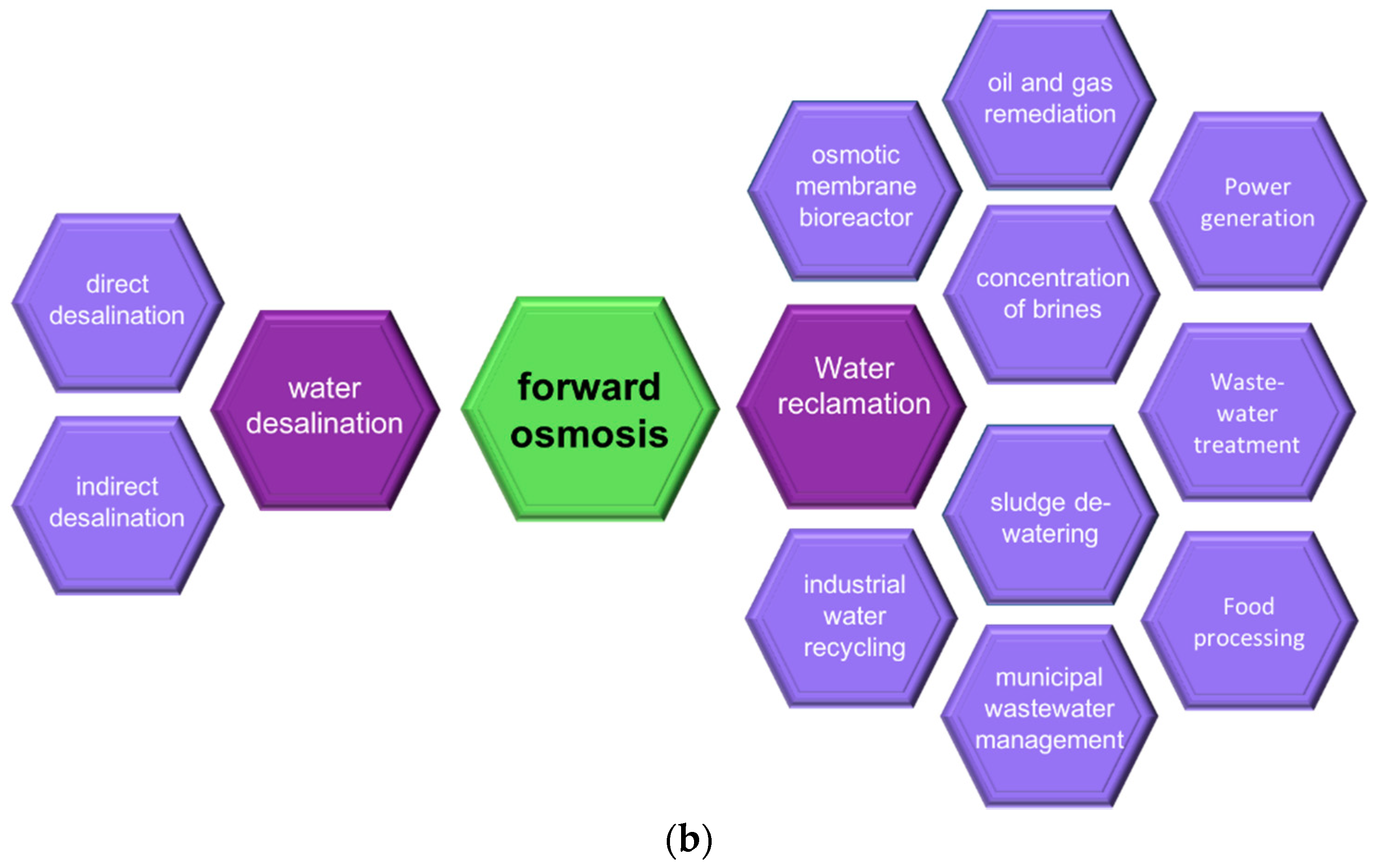
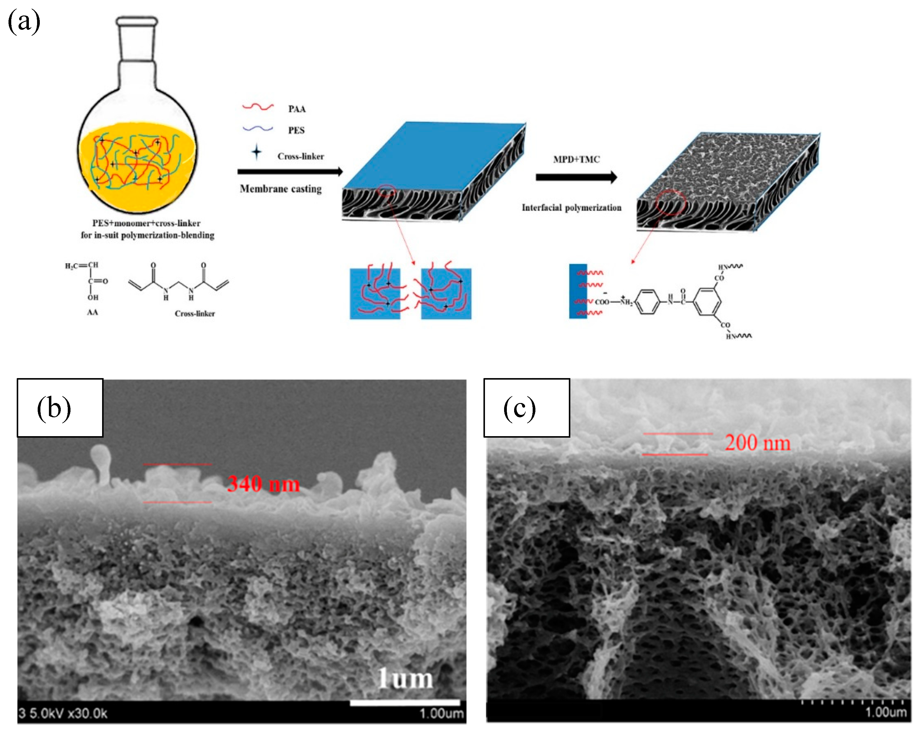
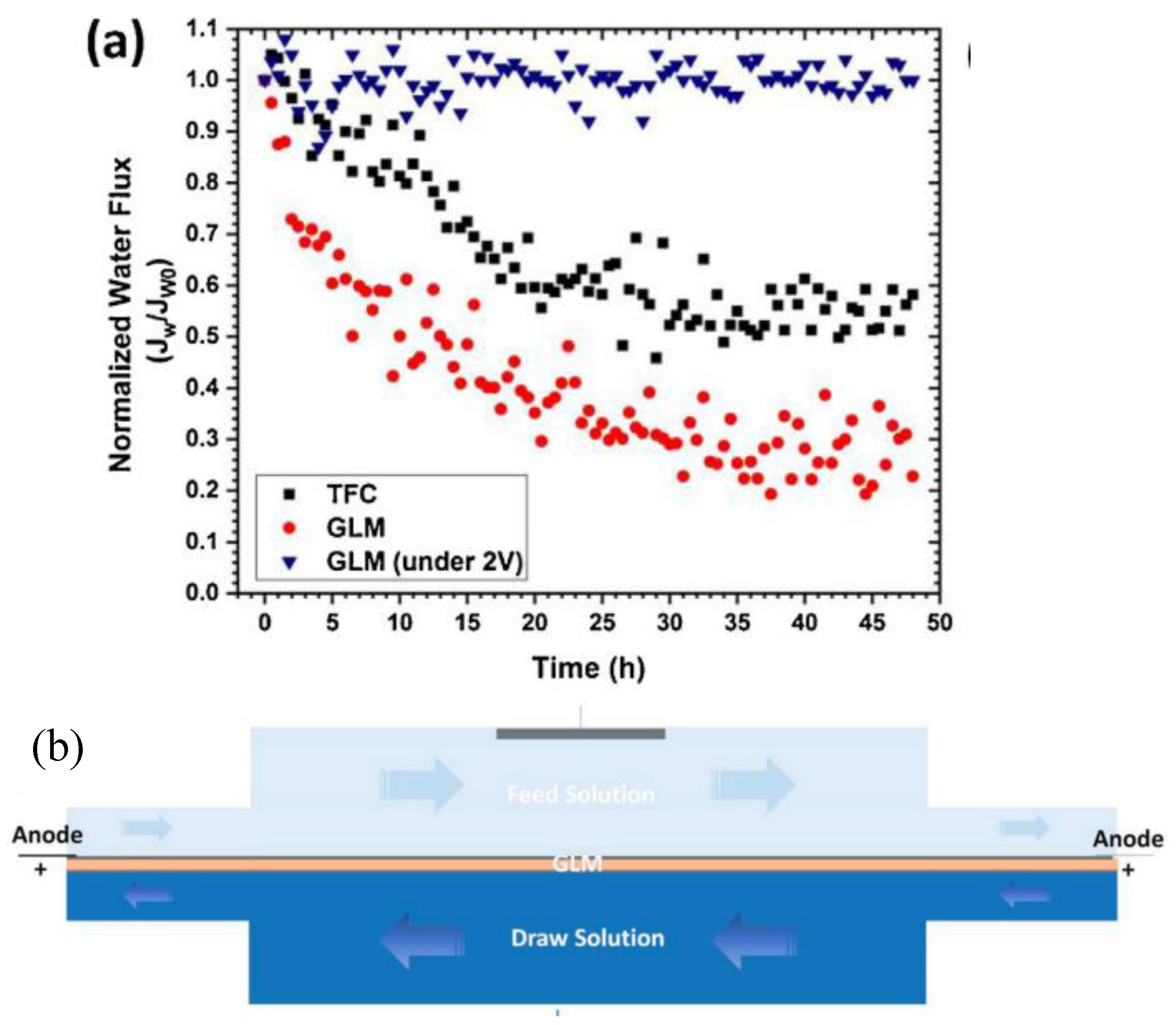
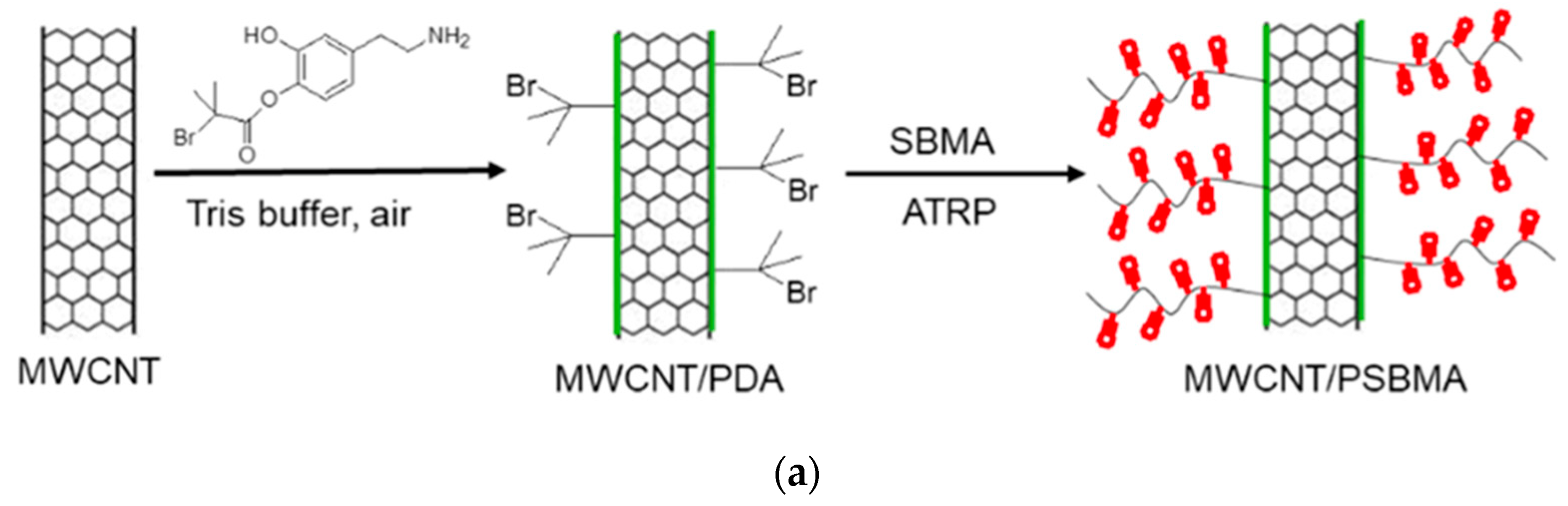
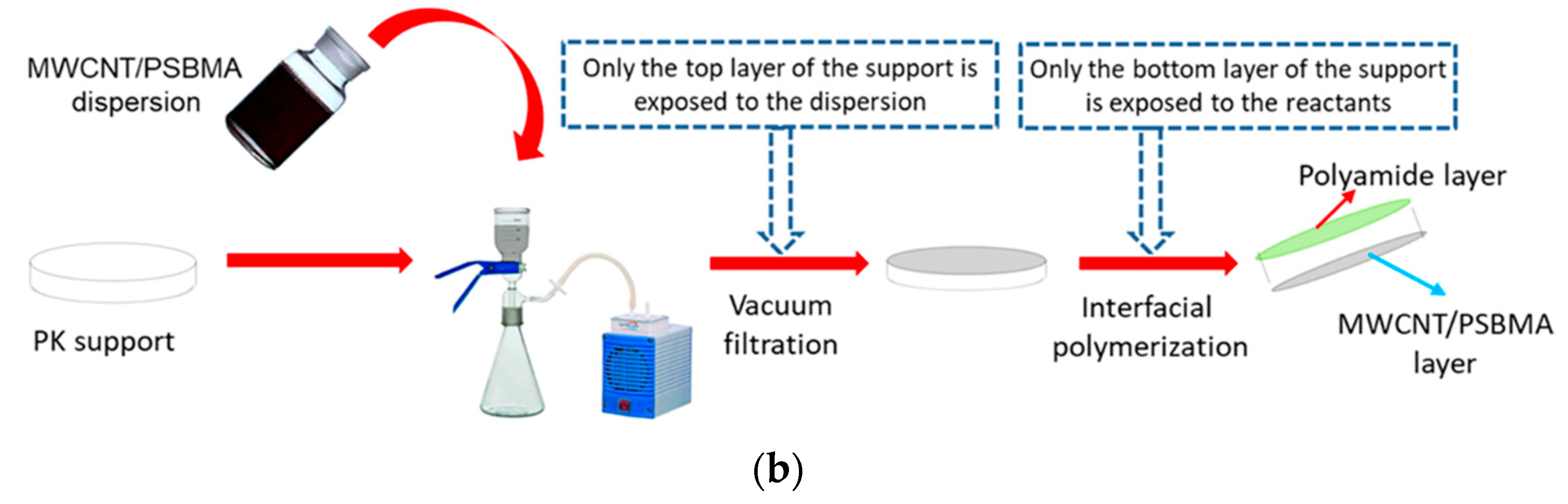
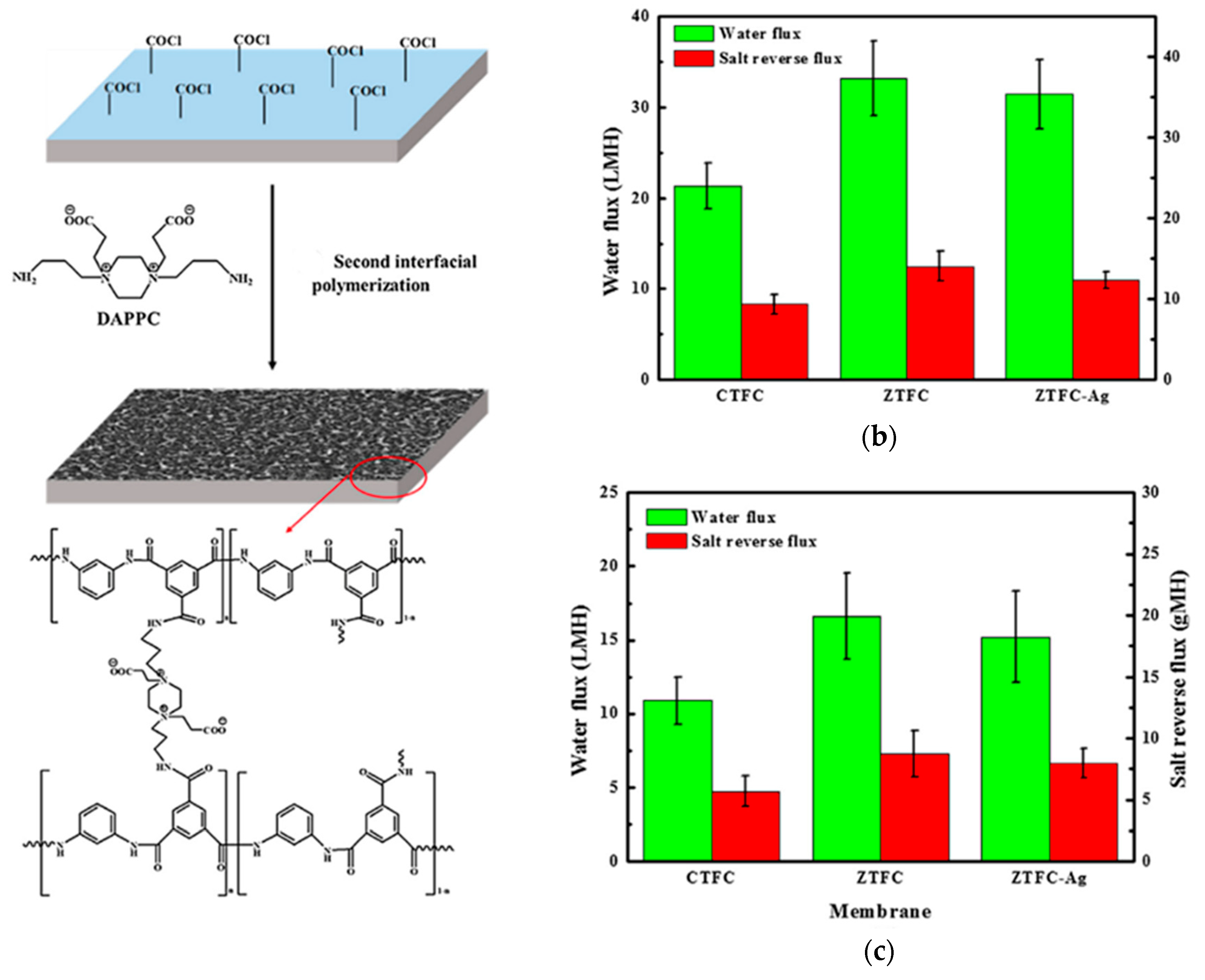
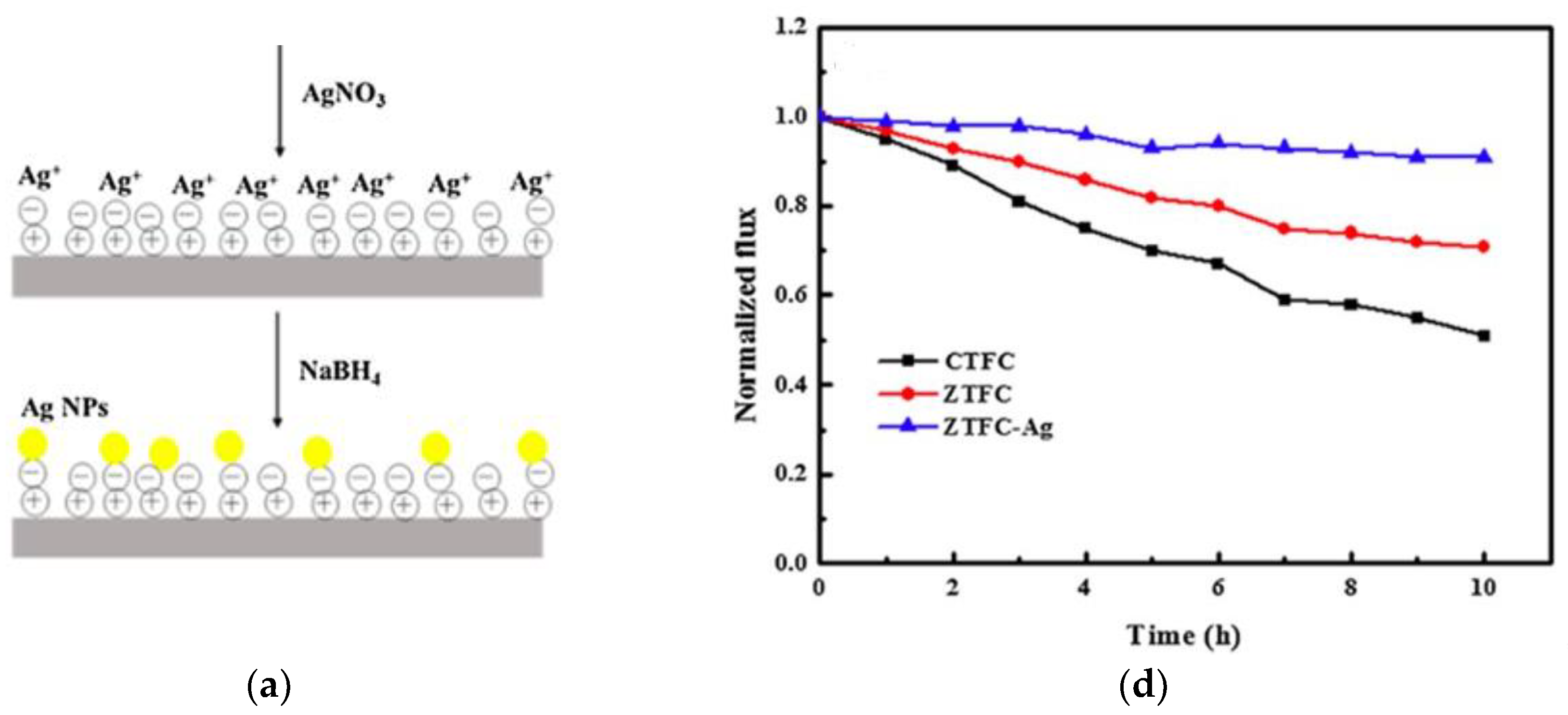
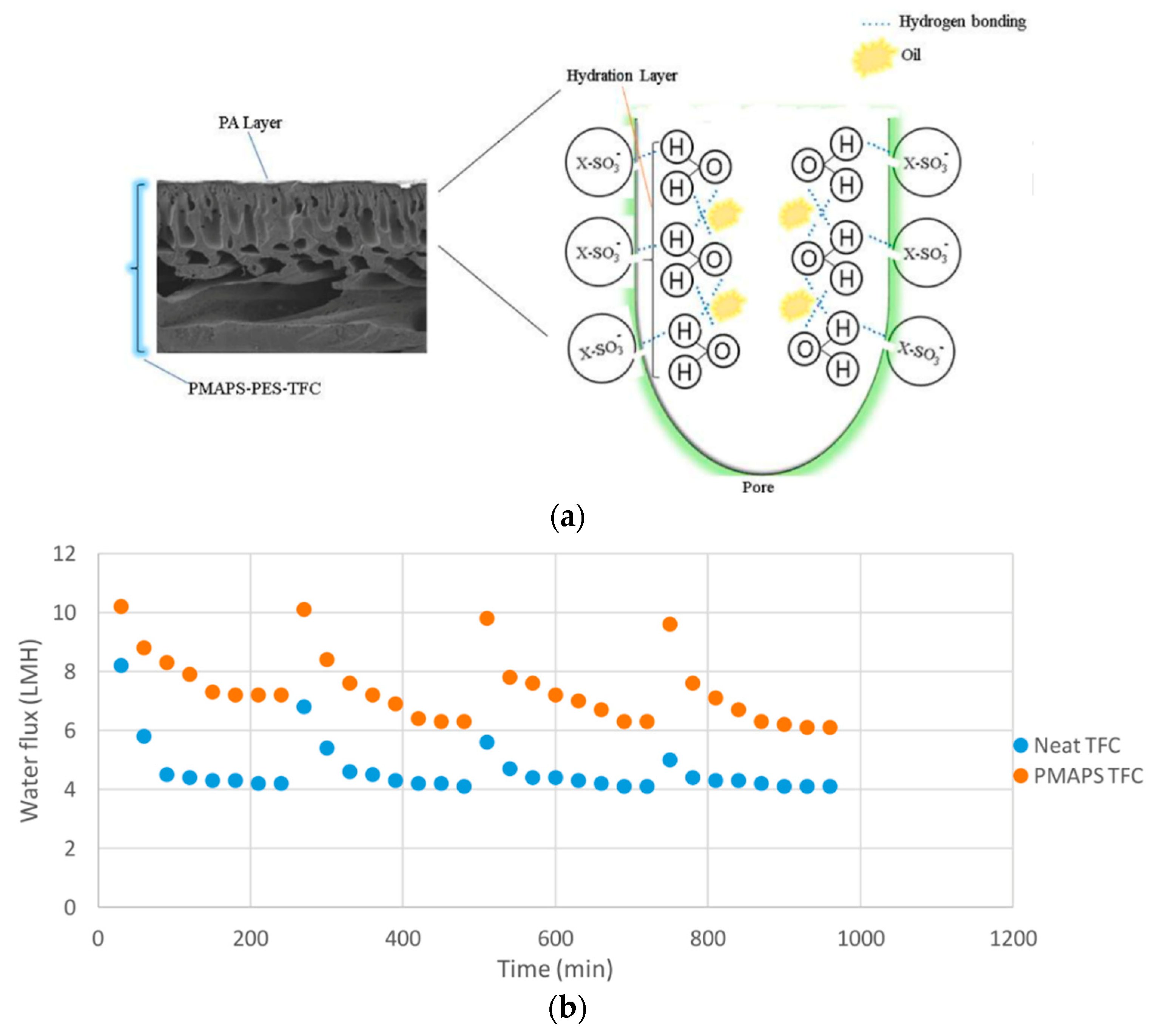
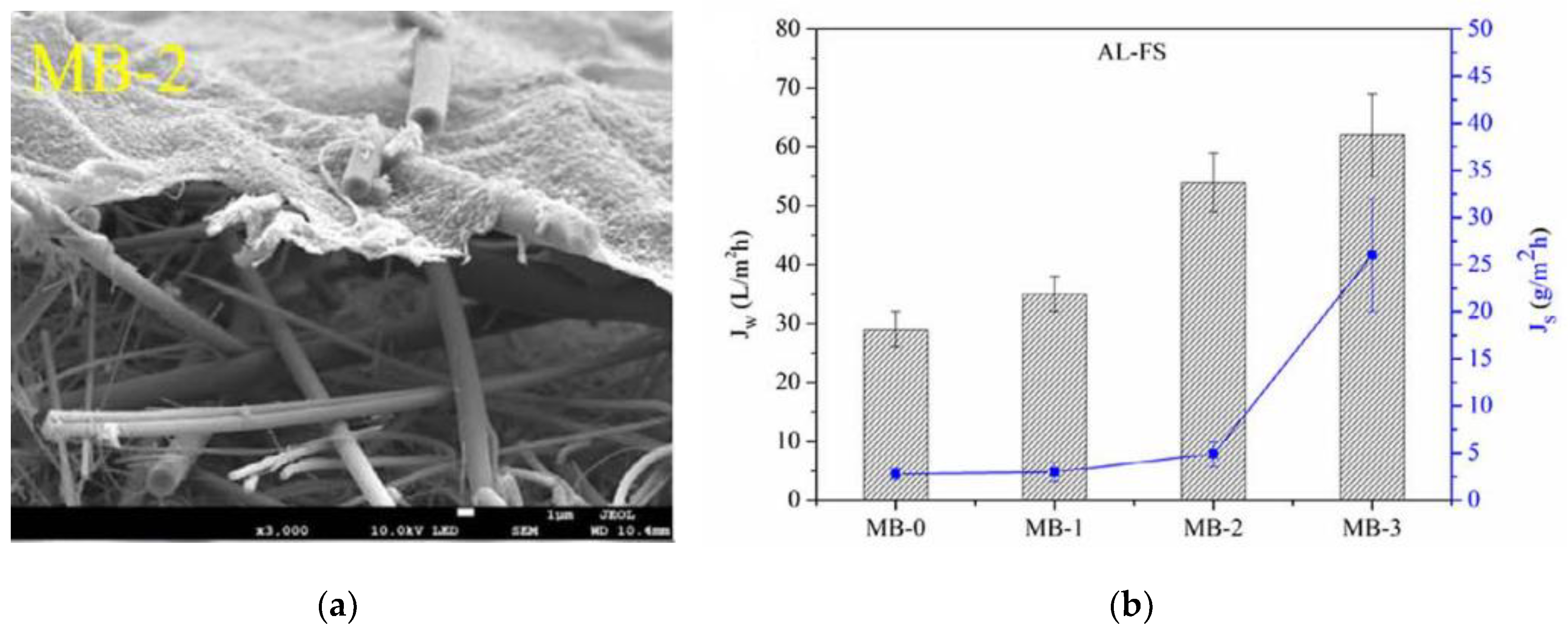
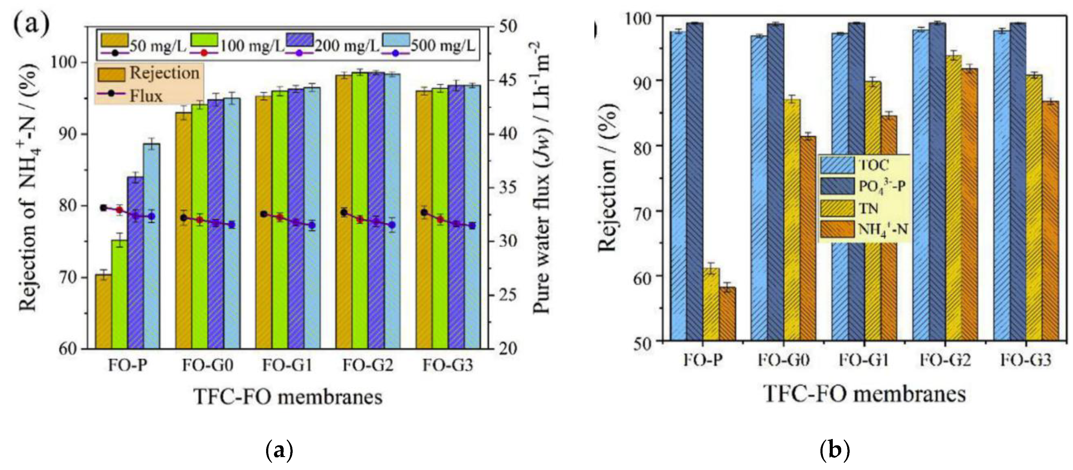
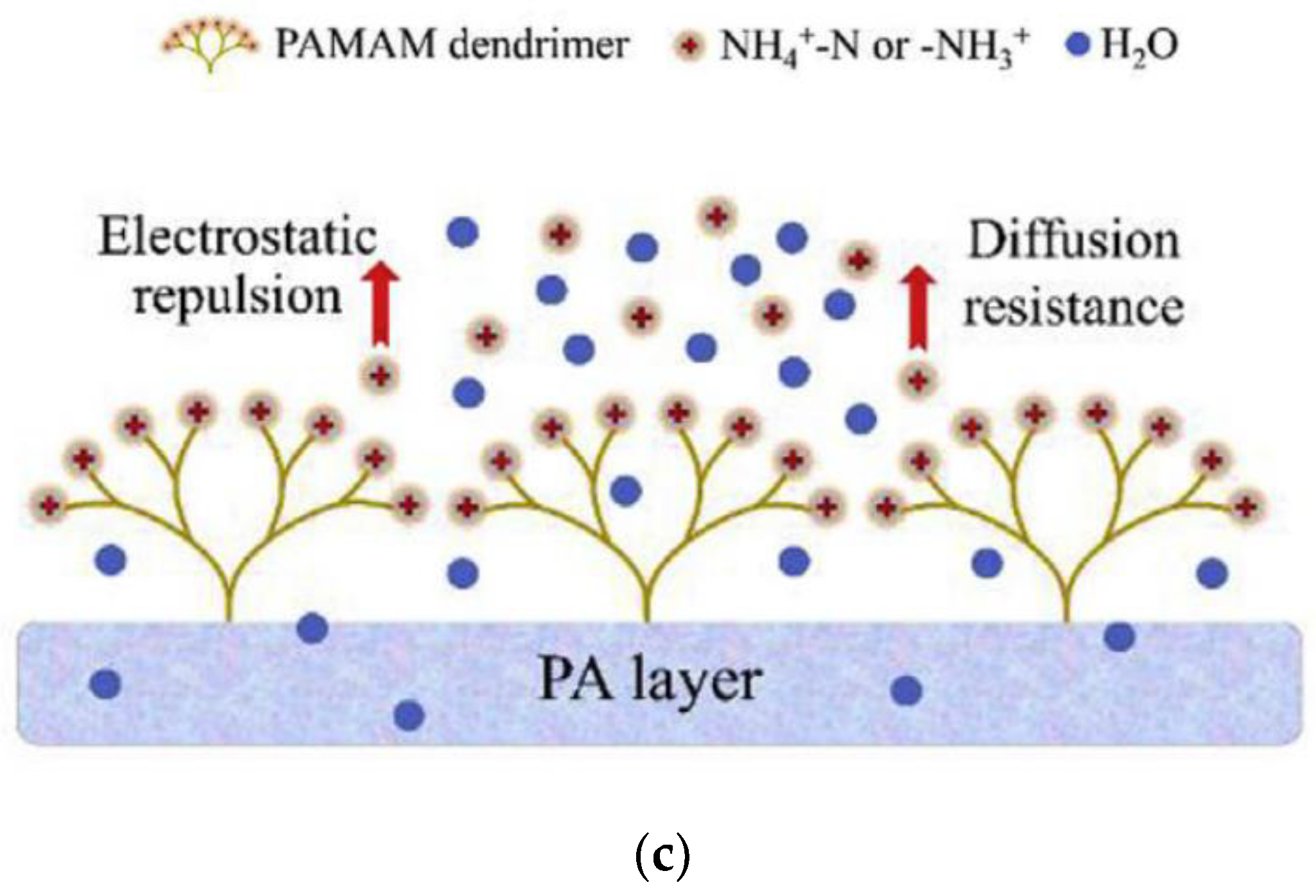
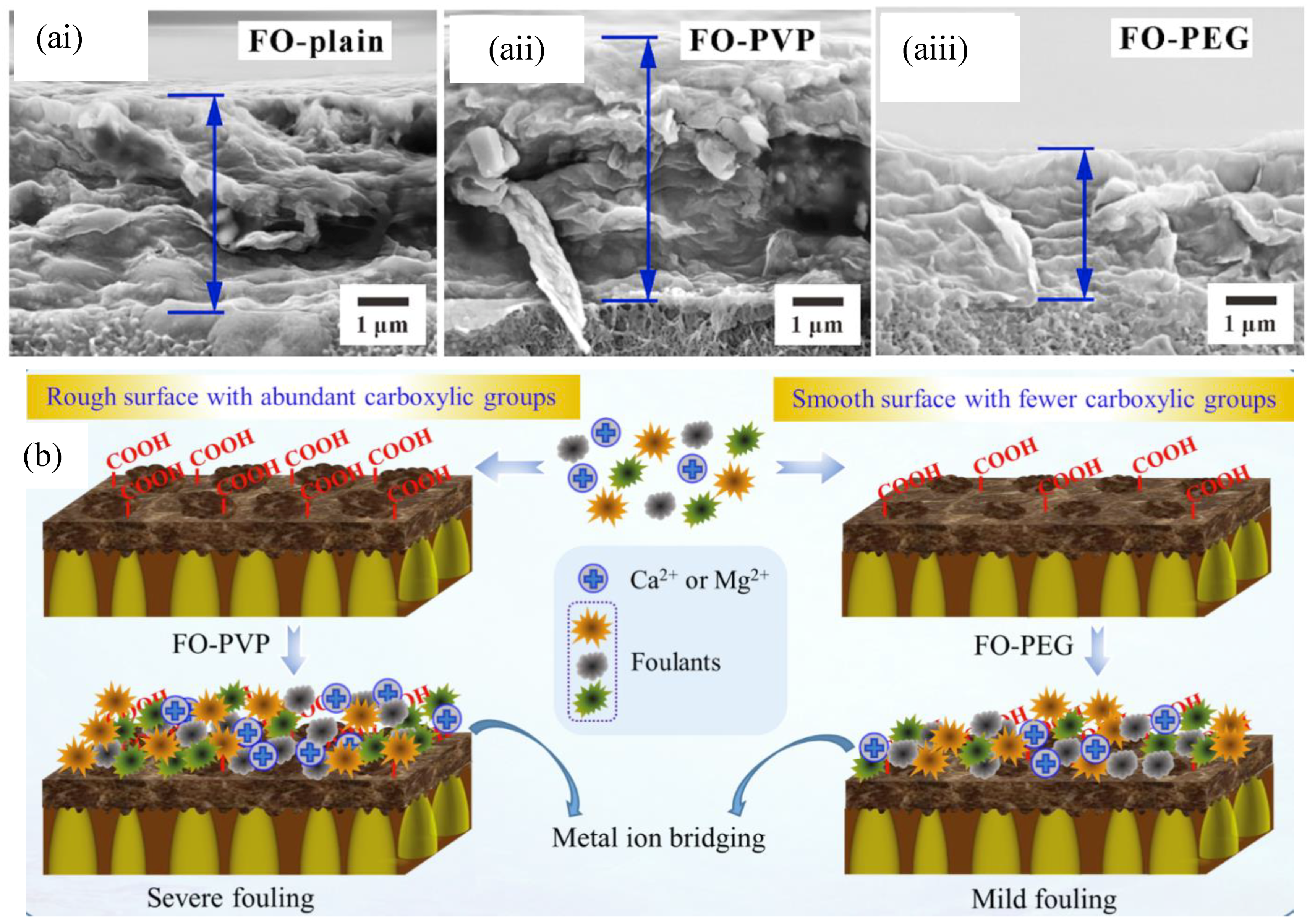
| Supplier | Materials/Commercial Name | Configurations |
|---|---|---|
| HTI | CTA-NW | SW |
| HTI | CTA-ES | SW |
| HTI | TFC | SW |
| Aquaporin A/S | AqP | SW, HF |
| Oasys Water | Thin film composite (TFC) | SW |
| Porifera | PFO element | SW |
| Toray | FO membrane | SW |
| Fluid technology solution | Cellulose triacetate (CTA) | SW |
| Modern water | - | SW |
| Toyobo | - | HF |
| Trevi System | - | SW |
SW—spiral wound, HF—hollow fiber.
Table 2.
Performance evaluation of FO membranes in various wastewater treatment applications.
| Application | Membrane | Feed Solution | Draw Solution | Rejection | Flux | Ref |
|---|---|---|---|---|---|---|
| Oily wastewater | NH2-BPSH100 grafted PA TFC | Soy bean oil/water emulsion | NaCl | 99.9% | 15 LMH | [50] |
| Oily wastewater | Aminoethyl piperazine propane sulfonate (AEPPS) grafted PA TFC | Produced water | NaCl | - | 15.2 LMH | [51] |
| Oily wastewater | (poly(3-(N-2-methacryloxyethyl-N,N-dimethyl) ammonatopropanesultone) (PMAPS) double skinned TFC | Synthetic cutting oil | NaCl | 99.9% | 13.7 LMH | [52] |
| Oily wastewater | PMAPS modified substrate TFC | Synthetic cutting oil | NaCl | 99% | 15.79 LMH | [53] |
| Heavy metal | Polyethersulfone (PES) hollow fibers | Cd2+ and Pb2+ solution | Biogas slurry | Cd2+ = 98.5% Pb2+ = 97% | 6.8 LMH | [54] |
| Heavy metal | Bovine serum albumin (BSA)- embedded PA TFC | Cd2+ Cu2+ and Pb2+ solution | NaCl | >99% | 45–50 LMH | [55] |
| Heavy metal | HTI TFC | Hg2+ solution | MgCl2 | 99/9% | - | [56] |
| Nuclear waste | CTA-ES | Co2+ solution | NaCl | 99.9% | 15.5 LMH | [57] |
| Nuclear waste | CTA-ES | Cs+ solution | NaCl | 96.24% | 9.7–19.3 LMH | [58] |
| Nuclear waste | Porifera TFC | medical radioactive liquid waste | NaCl | 99 | 21 LMH | [59] |
| Nuclear waste | CTA-ES | Co2+ and Cs+ solution | NaCl | Co2+ = 99% Sr2+ = 97% | 15 LMH | [60] |
| Domestic waste concentration | PAMAM grafted PA TFC | Raw domestic waste | NaCl | TOC, PO43−—P = 99% PO43−-P = 91% | 32 LMH | [61] |
| Domestic waste concentration | PEG modified substrate PA TFC | Raw domestic waste | NaCl | TOC 93% PO43−-P = 98% PO43−-P = 59 | 21.1 LMH | [62] |
| Contaminants of emerging concern (CEC), | Sulfonated polyphenylene sulfone (sPPSU)-PA TFC | aromatic aqueous solution | NaCl | Nitrobenzene = 75.2 Phenol = 72.1 Aniline = 91.5 | 22 LMH | [63] |
| CEC | Aquaporin Inside™ FO hollow fiber module | Trace ognic contaminants | NaCl | BPA = 99% methyl paraben = 95% | - | [64] |
* LMH = L m−2 h−1, TOC = total organic carbon.
© 2019 by the authors. Licensee MDPI, Basel, Switzerland. This article is an open access article distributed under the terms and conditions of the Creative Commons Attribution (CC BY) license (http://creativecommons.org/licenses/by/4.0/).
Share and Cite
MDPI and ACS Style
Goh, P.S.; Ismail, A.F.; Ng, B.C.; Abdullah, M.S. Recent Progresses of Forward Osmosis Membranes Formulation and Design for Wastewater Treatment. Water 2019, 11, 2043. https://doi.org/10.3390/w11102043
AMA Style
Goh PS, Ismail AF, Ng BC, Abdullah MS. Recent Progresses of Forward Osmosis Membranes Formulation and Design for Wastewater Treatment. Water. 2019; 11(10):2043. https://doi.org/10.3390/w11102043
Chicago/Turabian StyleGoh, Pei Sean, Ahmad Fauzi Ismail, Be Cheer Ng, and Mohd Sohaimi Abdullah. 2019. "Recent Progresses of Forward Osmosis Membranes Formulation and Design for Wastewater Treatment" Water 11, no. 10: 2043. https://doi.org/10.3390/w11102043
Note that from the first issue of 2016, this journal uses article numbers instead of page numbers. See further details here.