Hidden Impacts: Large-Displacement Stress Stiffening
Have you ever watched a musician playing music on a hand saw with a violin bow, changing the pitch by flexing the saw blade? The pitch changes because of large-displacement stress stiffening of the blade. These are the concepts we will review relating to pre-stressed modal analysis linked to nonlinear static analysis.
Ansys Mechanical (Workbench) v14.0 can consider the modal natural frequency of vibration analysis of a pre-stressed structure, even if the pre-stressed state is the result of nonlinear modeling. Nonlinearities can result from any combination of large displacement, nonlinear contact, or material nonlinearity in the analysis.
Some planning is required at the nonlinear static analysis stage, if required files are to be available to run the modal analysis for a chosen load step and substep choice from a nonlinear static analysis.
This article reviews some settings that can be studied by users who want to examine the technique. Note that the resulting modal analysis result can be sensitive to contact settings, mesh density, and other properties of the nonlinear static analysis—sensitivity analysis may be indicated.
The Nonlinear Static Analysis Setup that Supplies Pre-stress Information
The setup of the nonlinear static analysis must be suitable for accurate simulation even without a subsequent modal analysis. There are a few special considerations when a modal analysis is to follow the static analysis:
- Contact pairs need penalty stiffness values in both perpendicular and tangential directions set high enough that artificial modes of vibration are not created in which the penalty springs are excited. Where possible, Bonded and No-Separation contact pairs should use MPC settings so that this difficulty does not arise. Nonlinear contact pairs should use default or manual contact stiffness settings so that stiffness factors are 1.0 or greater, as long as this does not cause convergence difficulties.
- Information for both Restarts and Results must be stored for any nonlinear static substeps and load steps that are to be considered for modal analysis.
- Each modal analysis to be performed for a particular solution time (load step and substep) requires an additional modal system in the Project Schematic. As long as the static result of interest was saved, additional modal systems can be added to a Project Schematic. The modal analysis will not use interpolated times from the solution of the nonlinear static analysis—only a “closest” time saved result can be used.
- Nonlinear contacts are linearized for modal analysis. During modal analysis, wherever contacts are closed, rough contact is treated as bonded, frictionless contact is treated as no-separation, and frictional contact is treated as bonded. Wherever there is a gap, nonlinear not-closed contact elements are treated as open. Note that modal analysis uses virtual displacements, which are infinitesimal in magnitude. The individual contact elements do not open and close during the calculated modal response.
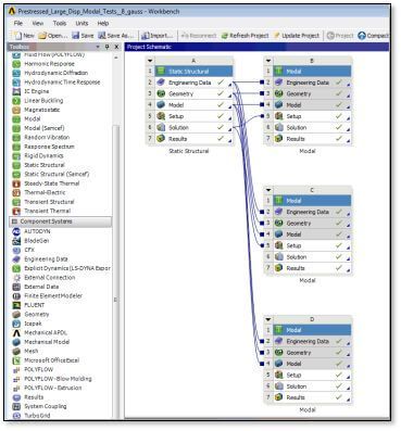
In the figure above, a static analysis is linked to 3 modal analyses. The first two import stresses from the static analysis; the third does not, and so will perform a modal analysis that is not pre-stressed.
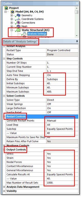
The figure below shows example Analysis Settings for a static nonlinear pre-stress analysis that will send its deformed shape and pre-stress condition to a downstream modal analysis.
Of particular interest for modal analysis is the plan for pre-stress output data required by the modal analysis. Restart points need to be generated for any substeps that are to be considered for the modal analysis. Those restart points should be accompanied by ordinary Output Controls points so that the static structure can be examined for any deformations at which modal analysis will take place.
In the figure below, the minimum number of substeps is 40, plus the Restart Controls and the Output Controls specify 40 “Equally Spaced Points”. “Equal spacing” of recorded substep results is usually approximate in nonlinear work. Modal analysis can only be performed for the results points that were saved—no interpolations are performed to give approximate results at times for which a solution was not stored.
In the figure above, links to systems “B” and “C” enable pre-stressed modal analysis. Choices will be made in systems “B” and “C” as to which result in the static analysis will be imported for the purpose of deforming and pre-stressing the modal analysis structure.
Pre-stressed Modal Analysis Settings
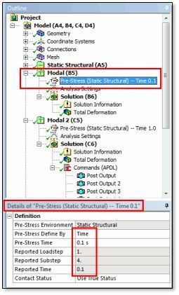
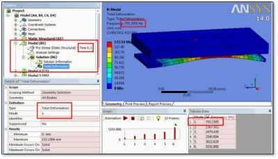
In the figure above, a Modal Analysis system has been chosen in the Outline, and the time at which a pre-stress result will be imported has been established. Note that in the Details setting, the user inputs a “Pre Stress Defined By” time. Alternatives include specification of the last result, or the end of a specific load step. The result closest in time as saved by the preceding Static Structural analysis will be used. The Reported Time that is shown in the Details in a grey box is the actual time that will be used. The Load Step and Substep for that time are also output. In this example the “Pre-Stress Time” happens to match the “Reported Time”; this will not always be the case for substeps.
A different Modal system will be needed for each different “Pre-Stress Define By” time that is to be evaluated.
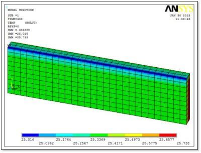
The example model has a fixed thick plate located above a flexible lower plate. An applied boundary condition on the lower plate bends it so that it touches the upper fixed plate. The natural frequencies of vibration of the lower plate are wanted when it is touching the upper fixed plate.
In the figure below shows a deformed shape calculated in an example nonlinear large-displacement static analysis. A thick fixed plate is above a thinner flexible flat plate. Contact between the plates resulted left of center in this image. This contact has a substantial effect on the natural frequencies of vibration of the lower plate.
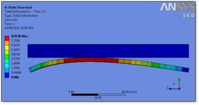
Whether the contact patch occurs at a single point, or is spread out over a large area, will affect the modes of vibration that develop. Users may need to perform sensitivity analysis on mesh density and contact penalty stiffness setting in order to assess whether the contact patch size is affecting the calculated modes of vibration.
In the figure below we see a listing of the first 6 modes of vibration for the structure. There is a plotting complication—the mesh is positioned in its original location in space, not at the deformed location calculated in the nonlinear Static run. Workbench at v14.0 does not plot mode shapes relative to the nonlinear pre-stressed large displacement shape. Modes calculated are for the deformed pre-stressed structure. To see mode shapes plotted relative to the deformed structure equilibrium position requires some APDL commands.
Making Views of Results Visible Relative to Deformed Shapes
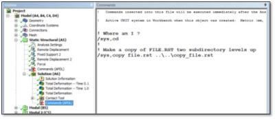
Planning is required for mode shapes to be plotted relative to the deformed structure. The first step is to place a copy of the RST file of the static analysis in an easily accessed location. This is done in the post-processing section of the Static Structural section of the Outline. In the figure below, we see an APDL Commands Object set of commands that copy the “file.rst” results file to a relative location two levels up in the subdirectory hierarchy:
Here is the text of the above APDL Commands Object for saving a copy of the RST file:
!
! Make a copy of FILE.RST two subdirectory levels up
/sys,copy file.rst ..\..\copy_file.rst
!
The static analysis RST file contains node deflection values for all of the saved substeps in the nonlinear pre-stress Static Structural analysis. As shown in the figure below, a second APDL Commands Object can be placed in the postprocessing section of each pre-stressed modal analysis to use those RST file results to move the nodes in the model to a new location by using the UPCOORD command. The deformed structure’s equilibrium position can then be plotted with an EPLOT command, and the mode shape relative to that equilibrium position can be plotted with commands such as PLDISP or PLNSOL. This does not affect Workbench Mechanical’s usual plots.
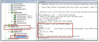
The “SET” command in the above APDL command set will need to be adjusted by the user to load the desired load step/substep combination, and should be coordinated with the load step/substep that is chosen by the “Pre-Stress” Details settings for each modal system. The SET command should not use times, because this will interpolate between results sets, whereas the “Pre-Stress” setting uses the nearest saved load step/substep.
The complete APDL Commands object used in the figure above is:
! Generate a plot of the vibration about the nonlinear deformed equilibrium position
! Demonstration only–use at your own risk
save,temporary___,db ! save current database
! Refer to the copied file from the static analysis above
! It contains node movements
file,..\..\copy_file,rst
! Read last result–same mesh, last substep
set,last
! Go to /prep7 to use the UPCOORD command
fini
/prep7
UPCOORD,1.0,ON ! move nodes by calculated displacement, zero deflections
fini
! Go back to /POST1
fini
/post1
! Point to and read first mode result from “file.rst”
file,file,rst
set,1,1
! Plot the elements as they were moved by the prestress calculation
/RGB,INDEX,100,100,100, 0
/RGB,INDEX, 80, 80, 80,13
/RGB,INDEX, 60, 60, 60,14
/RGB,INDEX, 0, 0, 0,15
/show,png
/view,1,1,1,1
/gfile,600
/title,Deformed mesh as used in the calculation
eplo
! Plot the deflection about the deformed equilibrium
/title,Vibration amplitude about the equilibrium position
plnsol,u,sum
!
! Plot only the body with the MAT attribute “vibe_body”
! Deformation plots with undeformed edge
esel,s,mat,,vibe_body
nsle
/title,Deformed mesh as used in the calculation
eplo
/title,Vibration amplitude about the equilibrium position
plnsol,u,sum,2
/view,1,1,0,0
/title,Deformed mesh as used in the calculation
eplo
/title,Vibration amplitude about the equilibrium position
plnsol,u,sum,2
!
*get,myscale,GRAPH,1,DSCALE,DMULT ! what amplitude applied to movement
/dscale,1,0.5*myscale ! reduced amplitude plot
plnsol,u,sum,2
!
! Restore things…
/title
resume,temporary___,db
/delete,temporary___,db
set,1,1
/dscale,1,1
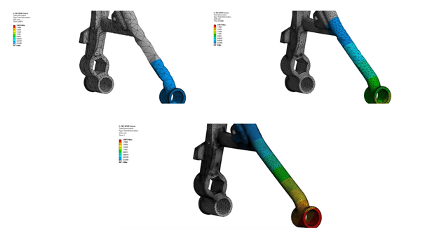
Several Mechanical APDL images are formed by the commands above. Three are shown below, and can be re-programmed by users as needed.
Nonlinearities in the Upstream Static Analysis
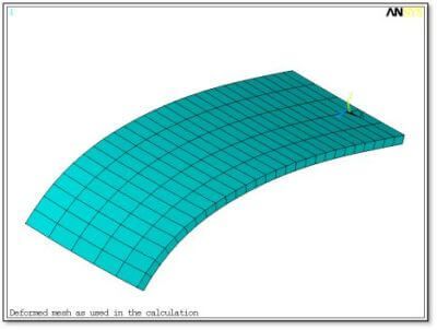
In the figure below shows the shape of the lower plate of the example model as imported from the nonlinear static analysis for a chosen load step/substep. This is a pre-stressed shape for which a modal analysis has been performed. The original part was flat—the curved shape resulted from loads and contacts in the static analysis.
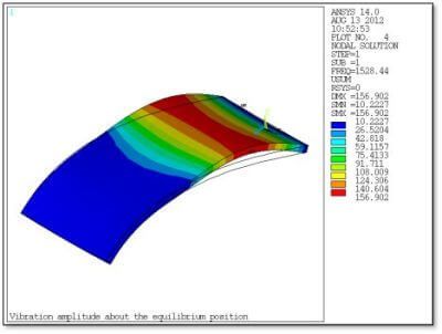
The first mode of vibration relative to the above pre-stressed shape is shown in the figure below. The PLNSOL command employed shows the outline of the non-vibrating shape.
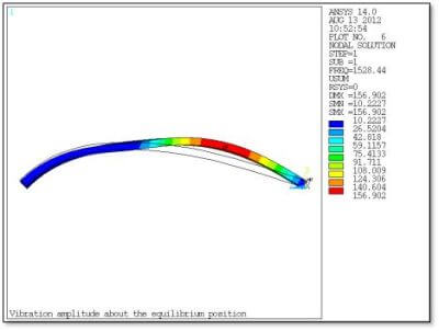
The figure below shows a front view for the same mode of vibration. Note that to the left of the contact region as seen in Figure 5 above, there is relatively little movement by the deformed shape—most of the kinetic energy in the vibration is in the larger region to the right of the contact zone.
Contact Penetration in Upstream Nonlinear
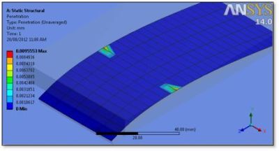
A plot of contact penetration in the upstream nonlinear static analysis is shown in the figure below. Contact stiffness and mesh density will affect how many elements are calculated to be in contact, which can affect whether the flexible plate in this example will rock in ROTX movement about one contact point on each side of the model, or whether it is somewhat fixed against rocking by a large flat contact patch.
In this example, soft penalty stiffness values will increase the size of the contact zone, but reduce the resistance to rocking about ROTX, so the calculated mode 1 is not highly sensitive to the stiffness setting. In general, this will be model dependent, so users are advised to think carefully about how contact modeling is done.
A detail to consider carefully in contact modeling is whether to use frictional or frictionless contact for certain nonlinear contact pairs. If frictional contact is used, even with a vanishingly small coefficient of friction such as 0.001, the modal analysis will linearize the contact region to act as bonded, preventing sliding motion where the contact is closed. If a frictionless setting is employed, the contact region will be linearized as no-separation.
Frictional vs. Frictionless Contact | Ansys Workbench
If the modal analysis contains significant contact sliding in the no-separation choice, the result will be affected by this choice of frictional versus frictionless contact. Users may need to evaluate models with each of these contact settings to see whether the contact Type setting is important in the resulting modal analysis.
Other typical considerations in modal analysis will be needed. The nature of assumed boundary conditions can affect a modal analysis, and various assumptions may need to be evaluated with independent models. As usual, a number of modes that is greater than the minimum number required should be evaluated to see whether there are other frequencies that could be of interest. This is particularly true with cyclic symmetry models.
Conclusions | Nonlinear Analysis Supplying the Pre-stressed Condition
Modal analysis has been illustrated with pre-stressed large displacement nonlinear analysis supplying the pre-stressed condition, employing new capabilities in v14.0 of Ansys Workbench Mechanical. APDL Commands Objects have been employed to plot mode shapes relative to the deformed structure’s equilibrium position. Example APDL commands have been included.
Nonlinearities in the upstream static analysis can include large displacement, contact, and material nonlinearity. The modal analysis is linearized about the deformed state that is imported from the static analysis. The effect of materials that have underdone nonlinear behavior has not been tested in the creation of this document. Users must plan how much information is to be stored during the nonlinear static analysis. That is, in order for the desired results data to be available in modal analysis or modal systems.
Ansys APDL Restart & Output Controls
Both Restart Controls and Output Controls must be set to make data available for desired “times” in the static analysis. In the “Pre-Stress” settings for the modal analysis, a choice of available load steps or times can be made by the user. A different modal system will be required in the outline for each result in the static analysis that is to be used for modal analysis.
A brief discussion of assumptions about contact settings warns users that these contact assumptions can affect results. A choice of frictionless versus frictional contact can significantly affect results in some models because they are linearized to no-separation versus bonded contact, respectively, during the modal system analysis. Mesh density and contact stiffness assumption can also affect some models, and sensitivity analysis (varying settings to see consequent results) is advised in general.
Contact for Additional Ansys Mechanical Support
Finally, we hope that you can make productive use of Pre-Stressed Modal Analysis, and varying supportive analysis’ for your Ansys Mechanical models. For more information, or to request engineering expertise for a particular use-case scenario surrounding modal analysis techniques, please follow the accompanied link.
Additional Ansys Software Tips & Tricks Resources
-
- Analyzing normal and Tangential Elastic Foundations in Mechanical
- Why Meshing is Crucial for FEA Fluid Simulations Prior to Prototyping
- For support on Contained Fluid FEA Modeling with HSFLD242 Elements
- For Exporting a Deformed Geometry Shape Post-Analysis in Mechanical
- Moreover, for guidance Multi-Step Analyses in Mechanical
- For Retrieving Beam Reaction Force in a Random Vibration Analysis
- Deploying Ansys Macro Programming vis *USE Command in Mechanical
- For replicating Fatigue Models from Start to Finish in Mechanical
- In addition, setting up Acoustic Simulations of a Silencer
- For a step-by-step guide on 2D to 3D Submodeling in Mechanical
- For modeling Pipe16 Circumferential Stress in Mechanical
- For Support on performing ‘EKILL‘ in Workbench
- APDL Command Objects post-Spectral Analysis
- For Separating DB Database Files from RST Files
- Measuring Geometric Rotation in Mechanical WB
- Explicitly, CAD Geometry Deformation Plasticity
- Offsetting a Temperature Result to Degrees Absolute
- For general guidance on Ansys Post-Processing
- Finally, for basic Ansys Software Installation and License Manager Updates