Recent Developments and Future Challenges of Hydrogels as Draw Solutes in Forward Osmosis Process


1
State Key Laboratory of Urban Water Resource and Environment, Harbin Institute of Technology, Harbin 150090, China
2
School of Civil Engineering and Transportation, Hebei University of Technology, Tianjin 300401, China
3
College of Urban Construction and Environmental Engineering, Chongqing University, Chongqing 400044, China
*
Authors to whom correspondence should be addressed.
Water 2020, 12(3), 692; https://doi.org/10.3390/w12030692
Submission received: 7 January 2020
/
Revised: 6 February 2020
/
Accepted: 24 February 2020
/
Published: 3 March 2020
(This article belongs to the Special Issue Hybrid Systems Using Different Technologies for Wastewater Treatment and Reuse)
Abstract
:Forward osmosis (FO) has been recently regarded as a promising water treatment technology due to its lower energy consumption and lower membrane fouling propensity compared to the reverse osmosis (RO). The absence of suitable draw solute constraints the wide-range application of the FO. Hydrogels are three-dimensional hydrophilic polymer networks that can absorb a huge amount of water. Particularly, stimuli-responsive polymer hydrogels can undergo a reversible volume change or solution-gel phase transition in response to external environmental stimuli, including temperature, light, pressure, solvent composition, and pH. These intrinsic properties indicate the lowest regeneration cost of draw solutes compared to the thermal method and other membrane processes. This review aims to introduce the research progress on hydrogels as draw solutes, clarify the existing problems and point out the further research direction.
1. Introduction
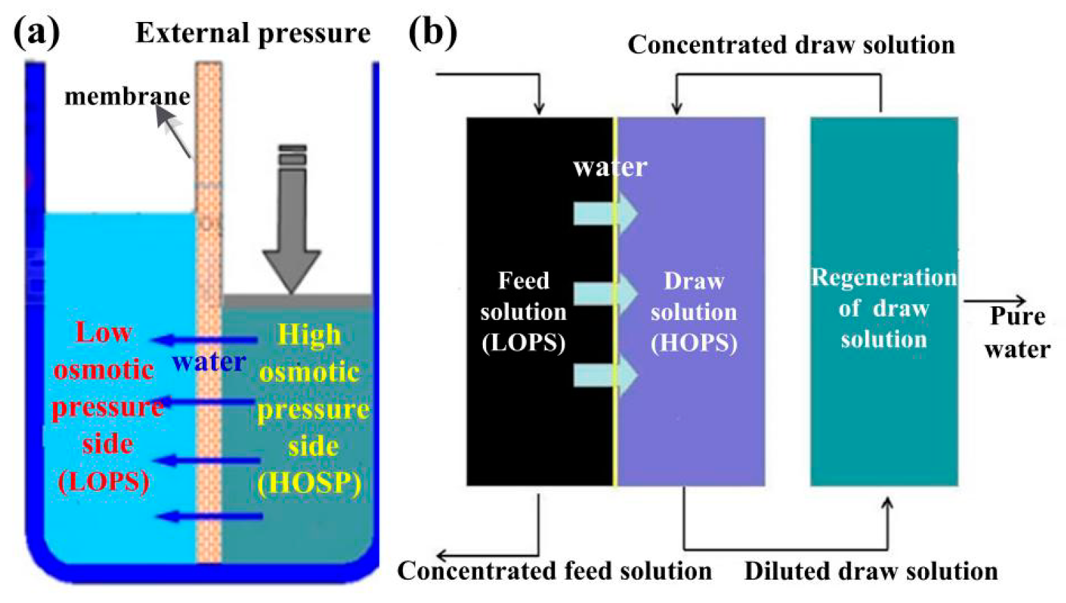
Water scarcity has become a global issue because of accelerating population growth and environmental pollution [1]. Wastewater treatment and seawater desalination are the promising means of increasing the available supply of fresh water [2,3]. Membrane technology is one of the most important and versatile methods currently available for environmental quality control [4], since the investment, operation, management, and maintenance costs of membrane treatment is significantly lower than that of traditional thermal methods. For example, the energy consumed to produce a cubic meter of clean water via reverse osmosis (RO) is below one-seventh of that of the multi-stage flash (MSF) and multi-effect distillation (MED) desalination [5]. Currently, RO has been the most popular industrialization method for its high selectivity, superior stability, easy operation, and scalability among these methods. However, RO uses high external pressure to drive water flow across a semipermeable membrane, and the external pressure promotes the contact between pollutants and membrane surface, accelerating membrane fouling [6]. Forward osmosis (FO) as an emerging membrane technology has received great attention around the world in the past few years [7,8,9,10,11,12,13]. FO utilizes the osmotic pressure gradient between a feed and a draw solute as the driving force rather than the external pressure to facilitate the water permeation through the semipermeable membrane, as shown in Figure 1. Therefore, FO requires less energy and demonstrates lower fouling and scaling with a higher rate of fouling reversibility [14]. FO has been reported to have the potential for extensive applications, including waste-water treatment [15], desalination [16], energy production [17], biomedical applications [18], and food processing [19]. However, both FO membranes and suitable draw solutes are essential to the further development of high-performance FO processes [20].
Rapid progress in the fabrication of the FO membranes has been seen in the last decade. However, viable FO applications are limited to specific cases which do not require regeneration of the diluted draw solutions, e.g., fertilizers [21] and saccharides [22]. Lack of suitable draw solutes has become the major impediment to the widespread commercialization of the FO process.
2. Critical Parameters Related to Hydrogels as Draw Solutes in FO Process
2.1. Factors Affects the Water Flux
2.1.1. Osmotic Pressure
Osmotic pressure gradient between feed solution and draw solution is the driving force in FO desalination. An ideal solution´s osmotic pressure, as given by the Van’t Hoff equation, as shown in Equation (1) [23]:
where i is the dimensionless Van’t Hoff factor, c is the molar concentration of the solute (mol/L), R is the universal gas constant, and T is the thermodynamic (absolute) temperature (K).
Considering the concentration of draw solution is highly concentrated, the following equation can be used to estimate the osmotic pressure, as shown in Equation (2) [24]:
where is the osmotic pressure coefficient related with the solute number density. B, C, and D are the osmotic coefficients that can be determined experimentally by fitting experimental osmotic pressure data. It is clear that the osmotic pressure depends on solute concentration, the number of species formed by dissociation in the solution, solute´s molecular weight, and the solution temperature. This means that high solubility of draw solute induces high osmotic pressure and, therefore, can achieve high water flux. A solute with small molecular weight combined with high water solubility can generate higher osmotic pressure (on an equal mass basis) and, therefore, can lead to higher water fluxes.
2.1.2. Concentration Polarization
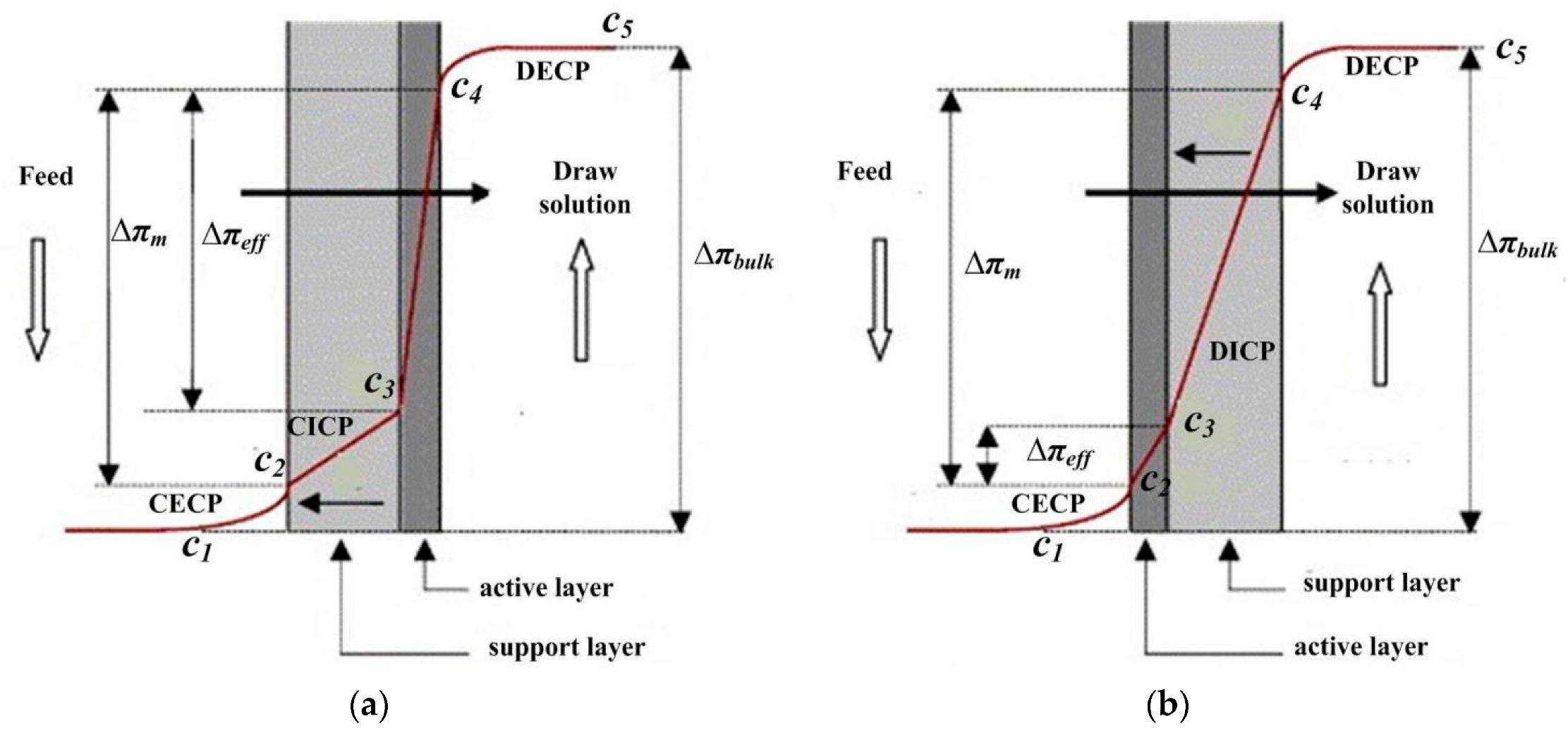
Concentration polarization (CP) arises due to the occurrence of concentration difference at the membrane-solution interface arising from the selective transfer of species through the FO membrane [25]. CP can be classified as internal concentration polarization (ICP), which exists at the membrane support layer, and external concentration polarization ((ECP), which occurs within the membrane active layer surface, as shown in Figure 2.
Concentrative ECP (CECP) takes place when the dense active layer faces the draw solution due to the diffusion of water from the side of the feed to that of the draw solution, resulting in the accumulation of draw solute in the active layer face, whereas dilutive ECP (DECP) occurs when the dense active layer faces the draw solution due to the diffusion of water from the side of feed to that of the draw solution [26].
ICP results from the inability of the solute to penetrate the dense selective layer of the membrane easily. Concentrative ICP (CICP) occurs where the feed solution facing the porous membrane support layer causes the feed solution to concentrate, whereas dilutive ICP (DICP) occurs when the porous layer faces the draw solution in FO desalination. The transport of water from the feed to the draw solution causes the feed solution to dilute [27].
Therefore, the osmotic pressure difference across the active layer is much lower than the bulk osmotic pressure difference, which results in a much lower water flux than expected. The reason is attributed to the two types of concentration polarization (CP) phenomena, including external CP (ECP) and internal CP (ICP), as discussed below. Research has shown that the major factor contributing to the decline in the water permeation rate in FO desalination is the ICP [28].
2.2. Reverse Solute Diffusion
A small amount of draw solute will permeate across the membrane from the draw solution to the feed solution owing to the difference in solute concentrations. Reverse solute diffusion is behind the ICP phenomenon in FO desalination. Reverse draw solute diffusion can cause severe ICP. The loss of an expensive draw solute would increase the operation cost, and even additional treatment of the feed concentrate would be required before its discharge to the environment if the draw solute is harmful to the environment [29].
2.3. Regeneration of Draw Solutes
Diluted draw solutes must be separated from freshwater. Many regeneration processes have been suggested for FO, including pressure-driven membrane, thermal separation, precipitation, electro-dialysis, stimuli-response, and combined processes [30].
2.4. Operation Cost
The operating cost contains three parts, including the cost of draw solutes and FO membrane, FO process, and the regeneration of draw solutes. The recovery of draw solutes takes a significant energy cost in FO technology implementation, especially for nonintelligent responsive draw solutes, such as the theoretical minimum energy consumption during regeneration via crystallization and RO was higher than that of standalone RO for seawater desalination at the same water recovery [31]. Therefore, easy regeneration is very important for the practical application. Besides, the batch mode in the FO process and regeneration of draw solutes not only increases the operation cost but also reduces the apparent water flux. Therefore, realizing continuous water production is another method to decrease the operating cost.
3. Major Problems Associated with Hydrogels as Draw Solutes in FO Process
Desirable draw solutes are supposed to possess high osmotic pressure, be nontoxic, exhibit low reverse flux, and be easily and rapidly regenerated without significant loss of the draw agent [32]. Intelligent hydrogels not only can produce high-swelling pressure when specifically designed but can also be regenerated by external stimuli, such as temperature [33] and pH [34]. Moreover, they have low reverse diffusion rates because hydrogels are insoluble in water. Thus, various hydrogels were studied as draw solutes in the FO process over the past few years [35]. However, there are several issues that still need to be addressed, including the low water flux, high external concentration polarization, difficulties in regeneration, and in-continuous operation. This review aims to introduce the research progress of hydrogels as draw solutes, clarify the existing problems, and point out the further research direction.
4. Recent Development of Hydrogels as Draw Solutes in FO Process
Various hydrogels were studied as draw solutes in the FO process over the past few years, as shown in Table 1. Various methods were applied to enhance the water flux, reduce external concentration polarization, realize low-cost regeneration of draw solutes, and continuous operation. Therefore, the research progress on various hydrogels as draw solutes will be introduced with regard to these aspects.
4.1. Enhancing Water Flux by Changing Monomer Composition of Hydrogels
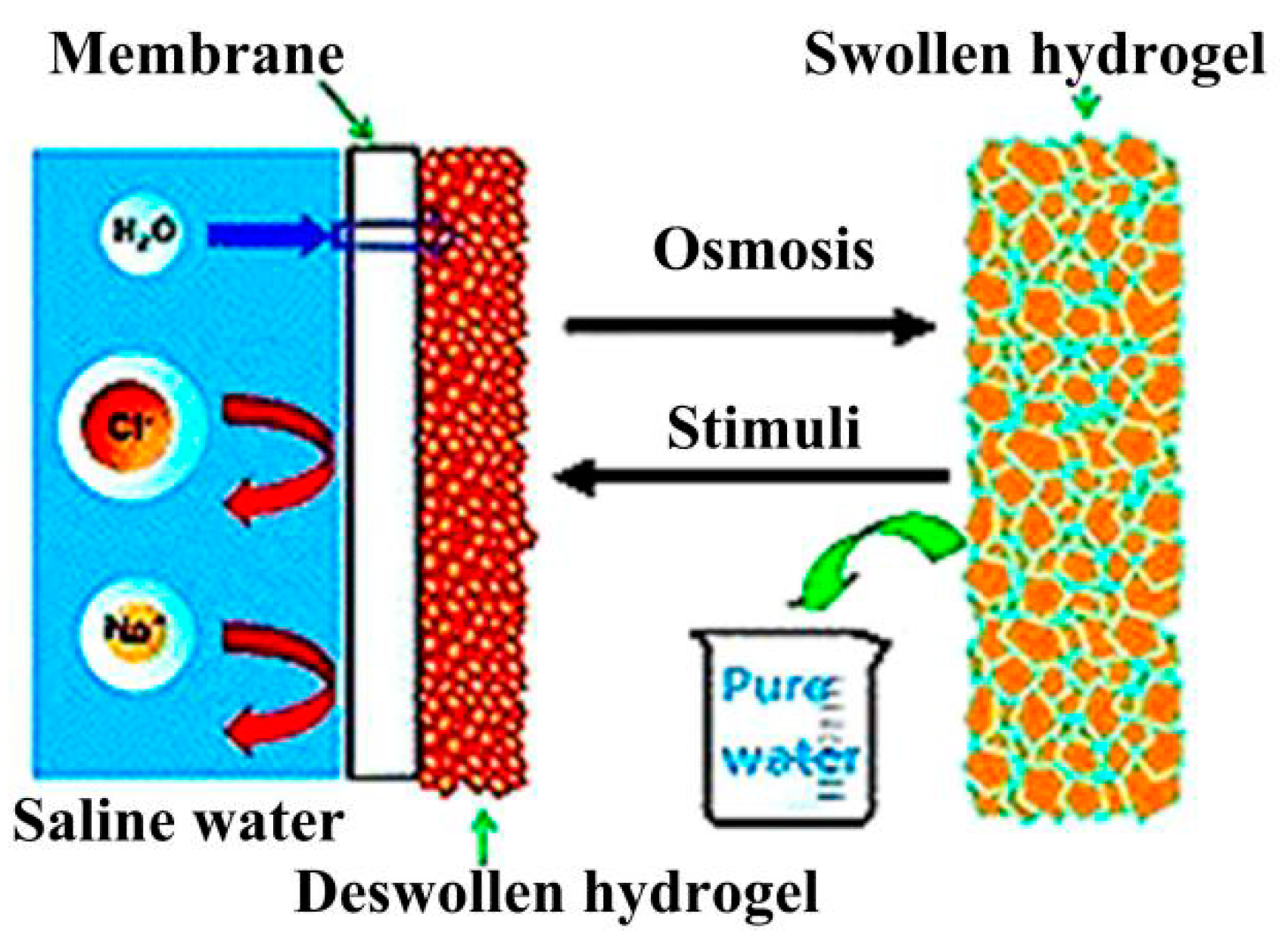
Since the osmotic pressure is regarded with the dissociation degree and hydration ability, Li et al. were first to study the effect of charge density on osmotic pressure, as shown in Figure 3. Ionic hydrogels produced higher water flux than that of non-ionic hydrogels. However, the water recovery rate demonstrates an opposite trend. For example, the water recovery rate of poly (sodium acrylate) (PSA) under elevated temperature (50 °C) was only 3% [36]. While poly (N-isopropylacrylamide) (PNIPAm) possesses a unique thermo-responsive characteristic to shrink with the water release when heated above a lower critical solution temperature (LCST) [37,38], co-polymerization of monomeric electrolyte with NIPAm was an obvious compromise. The lower critical solution temperature (LCST) is the critical temperature below which the components of a mixture are miscible for all compositions. Charged moieties and strong hydration both limit the water-recovery performance. Subsequently, Dai et al. investigated non-ionic thermo-responsive microgels as draw agents for FO desalination and elucidated their behavior in FO by analyzing the total Hansen solubility parameter (δt). The small difference in δt suggested the monomer has a strong affinity to water. The best apparent water flux (6.1 L/m2 h (LMH)) was shown for NIPAm95-AM5 prepared by co-polymerization of N-isopropylacrylamide (NIPAm) and acrylamide (AAm) with a mass ratio of 95:5 [39].
Since polyelectrolyte hydrogels produce high osmotic pressure, various thermo-responsive poly(ionic liquid) (PIL) hydrogels were also studied as smart draw agents for the FO desalination. Kim et al. synthesized a series of thermo-responsive copolymers P(MTxEOy) via free radical polymerization by using (2-(methactyloyloxy) ethyl) trimethylammonium chloride (MTAC) MTAC and 2-(2-methoxyethoxy) ethyl methacrylate (MEO) as monomers [40]. Water flux and recovery of 0.1 g/mL P(MT20EO80) reached to 5.45 LMH and 99.80%, respectively. Kim et al. also prepared a series of oligomeric poly (tetrabuylphosphonium styrenesulfonates)s (PSSP) with LCST of 60 ℃. The water flux of PSSP was slightly lower than that of monomeric SSP in the FO system, and a negligible reverse solute flux was observed in PSSPs, indicating that the oligomers were more suitable as draw solutes in the FO system than monomers [41]. Thermo-responsive poly (ionic liquid) TVBP-C6 hydrogels, which were prepared with the copolymer of (tributyl-4-vinylbenzylphosphonium)-based alkyl sulfonate counterion using a mixture of poly(propylene glycol) (PPG) and poly(ethylene glycol) (PEG) as crosslinkers, were also evaluated as intelligent draw agents for the FO desalination [42]. All of the above results indicate that the water flux of polyelectrolyte hydrogels as draw solutes shows a dramatic decrease with the reduction of ionic composition and the reduced response with increasing ionic content and the mutual interference between different polymer network structures [36]. Wang et al. effectively solved the reduced response problem by constructing interpenetrating network hydrogel (HPIPN) [43].
Since the counter ions are known to provide a positive osmotic pressure, monomer with different dissociation constants (pKa) can significantly affect the FO performance of hydrogels [36]. Hartanto et al. systematically investigated the effect of functional acidic co-monomers with different pKa on the FO performance of NIPAm-based thermo-responsive microgels [44]. Their results suggested that the equilibrium swelling time (EST) varies inversely with the ionization degree of co-monomer and its hydrophilicity, which is associated with the increase in the diffusion coefficient. However, volume phase transition temperatures (VPTT) and apparent water flux demonstrate the opposite behavior. For example, the shortest equilibrium time of 40 min was observed in MCG-NP-AMPS (microgel-NIPAm-2-acrylamino-2-methylpropane sulfonic acid), whereas the apparent flux of MCG-NP-AMPS was close to zero due to its weak response to the temperature change. Therefore, a low water recovery rate still has to be addressed.
Furthermore, Hartanto et al. studied the influence of the chemical structure of the cationic monomer on the FO performance of microgels [45]. Microgels are the hydrogels with micron size. Microgels with aliphatic cationic comonomers showed higher water flux than those with aromatic cationic comonomers, and the opposite behavior was observed in the dehydration process. The reasons can be attributed to the difference in the Hansen solubility parameters and the dissociation constants (pKa) of cationic comonomers.
Mungray et al. investigated fast-swelling superabsorbent polymer hydrogels as draw agents in the FO process for bovine serum albumin (BSA) enrichment. The hydrogels were synthesized by grafting acrylic acid (AA) and N-isopropyl acrylamide (NIPAm) monomers on a carboxymethyl cellulose (CMC) chain to improve swelling kinetics [46]. It was shown that a lower mass of hydrogels with a larger contact area is beneficial for obtaining higher swelling ratios, which are more suitable for the BSA enrichment, whereas hydrogels with a lower contact area and higher mass could obtain high water recovery rates in FO processes such as desalination or wastewater treatment.
4.2. Enhancing Water Flux by Reducing External Concentration Polarization
4.2.1. Reducing External Concentration Polarization by Introducing Composite Materials
Wang et al. prepared a 3D continuous hydrogel-polyurethane interpenetrating network hydrogel (HPIPN) [47] and incorporated hydrophilic microfibers into the polymer hydrogel to enhance water transport [48]. The water flux of hydrogel was significantly increased. For example, the water flux of HPIPN composites (17.9 LMH) is about eight times that of hydrogel powders (2.2 LMH) [48].
4.2.2. Reducing External Concentration Polarization by Reducing Hydrogel Size
According to gel dynamics theory, gel response time is inversely proportional to the square of the hydrogel size and proportional to the gel diffusion coefficient [49]. Therefore, the smaller the hydrogel size, the faster the swelling rate. Furthermore, the small size of hydrogel can increase the contact area between the FO membrane and gel.
Wang et al. for the first time investigated the effect of hydrogel size and size distribution on the performance of FO desalination [50]. Water flux was shown to increase with reducing hydrogel size due to increased contact area between the draw agents and the membrane surface. Moreover, the contribution of hydrogel-membrane contact areas to the water flux prevails over the contribution of hydrogel particle-hydrogel particle contact areas (Figure 4). Dai et al. synthesized submicron-sized copolymer microgels of NIPAm and acrylic acid by surfactant-free emulsion polymerization [51]. The microgel-based FO process allowed a high initial water flux reaching 23.8 LMH, whereas water recovery reached 72.4%. However, the water flux decreased to near zero after 5 h. Dai et al. subsequently synthesized cationic copolymer microgels with aliphatic and aromatic comonomers as draw agents. Cationic copolymer microgel containing 2-N,N′-(diethylamino) ethyl methacrylate (MCG-NP-DEAEMA) demonstrated the best overall performance; the initial water flux and water recovery were shown to be 45.6 LMH and 44.8%, respectively. MCG-NP-DEAEMA also displayed the shortest equilibrium swelling time that, in turn, reveals significant improvement in the apparent flux of 5.5 LMH compared with other cationic and anionic copolymer microgels [45]. However, synthesized microgels require further purification by dialysis before the start of the FO process, increasing the fabrication cost. As such, microgels have limited applications as draw solutes.
4.3. Various Methods to Realize the Regeneration of Draw Solutes
4.3.1. Enhancing Dewatering Rate by Changing the Network Structure of Hydrogel
Although the water flux can be enhanced by changing the monomer composition of hydrogels, introducing ionic groups into the hydrogel results in a compromise between its thermo-responsive property and deswelling rate. Moreover, higher LSCT values and denser skin layers cause the water molecules to travel out of the hydrogel networks, mostly in vapor form rather than liquid form, suggesting that the regeneration mechanism is, in essence, heat conduction [52]. Therefore, the ability to rapidly recover liquid water from hydrogel particles is crucial for the viability of the FO process. Researchers settled the problem mainly by enhancing heat transfer efficiency and enhancing water transport.
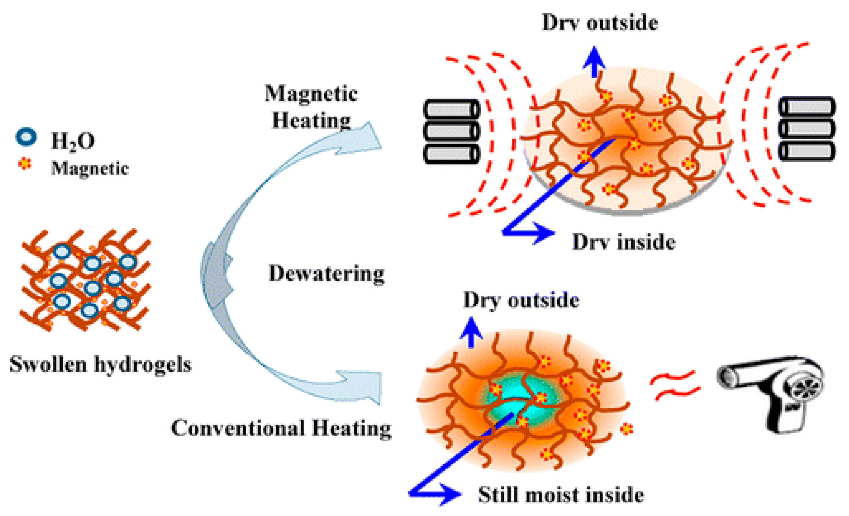
Wang et al. synthesized composite polymer hydrogels with light-absorbing materials, such as carbon particles (C) [53] and graphene sheets (rGO) [54]. The water recovery rate of PSA-NIPAM-C under sunlight with the radiation intensity of 1.0 KWm−2 for 60 min can reach 100%, whereas 227% enhancement in water flux was observed for PSA-NIPAM-1.2 wt% rGO relative to that of pure PSA-NIPAM. However, the conventional heating methods can result in a significantly higher temperature gradient, and hence, most of the recovered water is in a vapor state. Considering the magnetic field is virtually unaffected by the external isolating layers and does not depend on thermal conductivity, the research group subsequently synthesized nanocomposite polymer hydrogels with γ-Fe2O3 (Figure 5). Liquid water recovery of 53% was achieved under magnetic heating, as opposed to only 7% value obtained via conventional heating [52].
So far, most of the NIPAm-based thermally responsive hydrogels were prepared by random polymerization. Research results show that comonomers make a significant impact on the volume phase transition temperature (VPTT) of the hydrogel and its discontinuous transitions. The reason can be ascribed to the mutual interference within the polymer network structure, the large molecular weight distribution, and uncertain molecular structure [55,56]. For example, Li et al. for the first time investigated PNIPAm-co-PSA as a draw solute [36]. The water flux of PNIPAm-co-PSA was enhanced with the increase of SA content; however, thermally responsive dewatering behavior of PNIPAm-co-PSA tends to vanish.
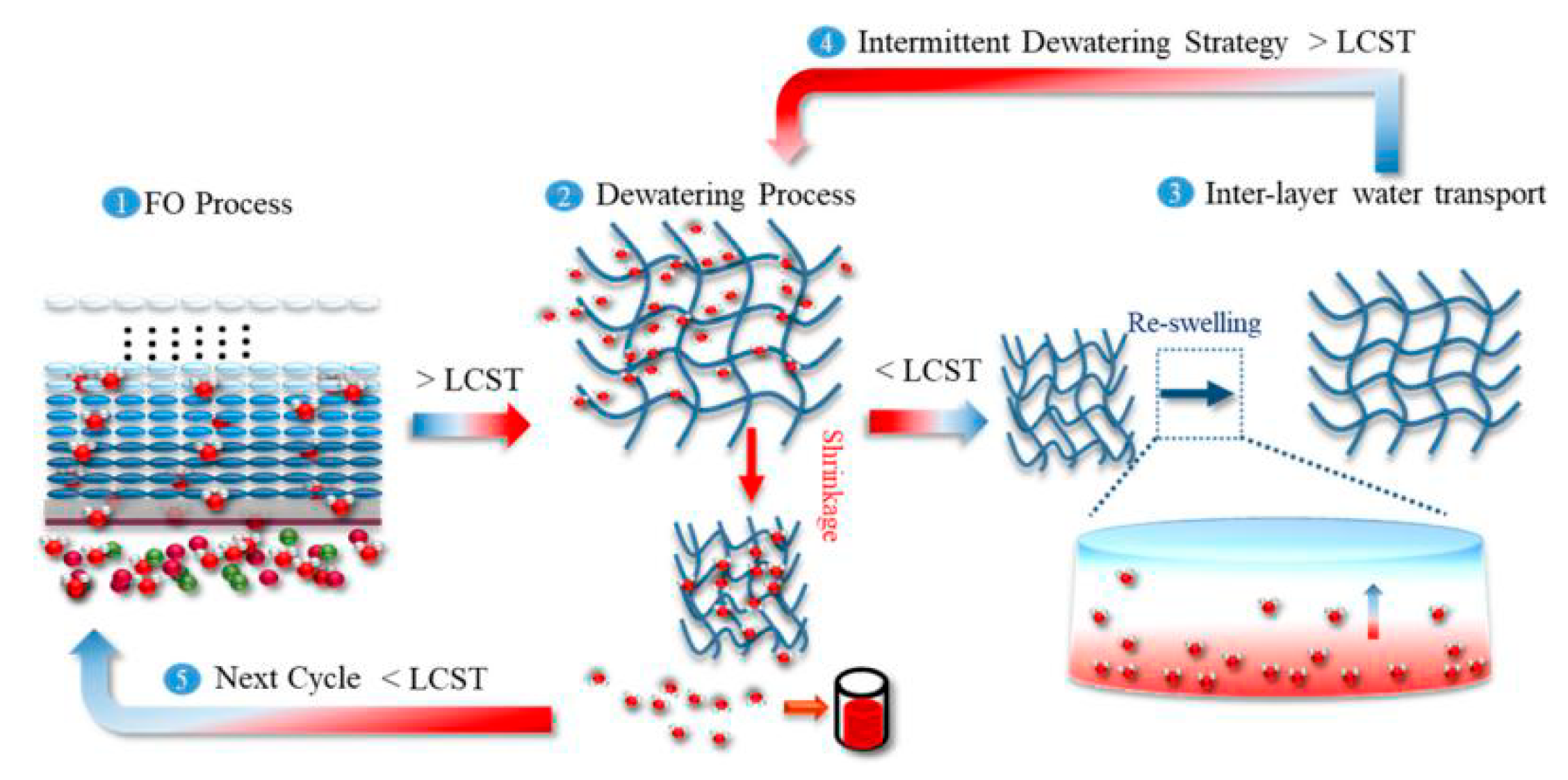
Interestingly, two independently crosslinked polymers with extensive physical entanglements constitute an interpenetrating network (IPN) hydrogels. In the IPN, the individual chemistry of PNIPA chains is not affected in contrast to the ambiance [57]. Hu et al. for the first time investigated semi-interpenetrating (semi-IPN) network hydrogels (such as PNIPAm-IPN-PSA and PNIPAm-IPN-PVA) as draw solutes in the FO process (Figure 6). These semi-IPN hydrogels displayed super thermally responsive behavior compared with NIPAm-SA copolymer hydrogels. The dehydration rate of PNIPAm-co-PSA can reach about 100% at 40 °C [43].
Block copolymers, which differ from random copolymers, retain their characteristic multiple components and demonstrate structural micro-phase separation [58]. Particularly, block polymers prepared by ring-opening polymerization have specific molecular structures and uniform molecular weight distributions, as such, having continuous phase transition temperatures [50]. Mungray et al. designed thermally responsive triblock copolymer hydrogels for brackish water desalination; PEG-PLA-PEG hydrogels are composed of hydrophobic poly (DL-lactic acid-co-glycolic acid) (PLGA) segments and hydrophilic poly(ethylene glycol) (PEG) segments. Hydrophilic PEG segments can form hydrogen bonds with water molecules associated at lower temperatures, favoring the formation of an aqueous solution [59]. At higher temperatures, hydrophobic forces of PLGA prevail over hydrogen bonds, causing a solution-gel transition. Moreover, introducing graphene oxide, which is a two-dimensional carbon material with a large number of hydrophilic oxygenated functional groups, enhances miscibility with the polymer matrix, allowing more hydrophilic composites to be formed.
4.3.2. Enhancing Deswelling Rate of Hydrogel by Applying Different External Stimuli
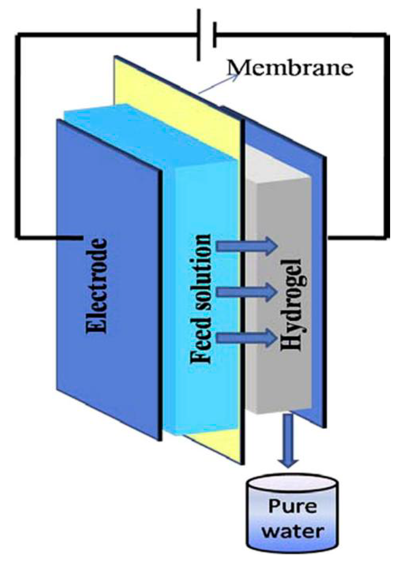
Apart from thermally responsive polymer hydrogels heated by the thermal method or magnetic field, a series of electrically responsive hyaluronic acid/polyvinyl alcohol (HA/PVA) polymer hydrogels were also studied as draw solutes by Zhang et al. (Figure 7) [60]. Compared with other published studies which have also used polymer hydrogels as draw agents in the FO process, reverse diffusion of the draw agent was avoided, and the complexity of the operation was minimized. Unfortunately, the initial water flux was lower than 2 LMH, even if DI water was the feed solution. Besides, there was a problem of the water electrolysis, because the applied voltage exceeded 1.23 V [61]. Subsequently, the research group proposed the introduction of ionic monomers to increase swelling pressure and conductivity. Various electrically responsive hydrogels were also investigated as draw solutes, such as 2-Acrylamido-2-methyl-1-propanesulfonic acid (AMPS) and 2-(Dimethylamino) ethyl methacrylate (DMAEMA) as monomers. The initial flux for A0.55D0.45 reached 2.09 LMH when even 2000 ppm NaCl solution was used as the feed solution [62].
Dai et al. developed gas-responsive cationic microgels as draw solutes for FO desalination, in which swelling and deswelling were driven by sweeping CO2 and N2, such as 2-N,N′-(diethylamino) ethyl methacrylate (DEAEMA) and 2-N,N′-(dimethylamino) ethyl methacrylate (DMAEMA) microgels [63].
To reduce the energy consumption for draw solute recovery after FO, magnetic poly (N-isopropylacrylamide-co-sodium 2-acrylamido-2-methylpropane sulfonate) (referred to as Fe3O4@P(NIPAM-co-AMPS)) nanogels were studied as draw solutes [64], while the draw solute was hard to be regenerated completely under the external magnetic stimuli for a week at 65℃. Further ultrafiltration was still needed to recover the residual.
4.4. Designing Continuous Semibatch FO Process to Enhance the Apparent Water Flux
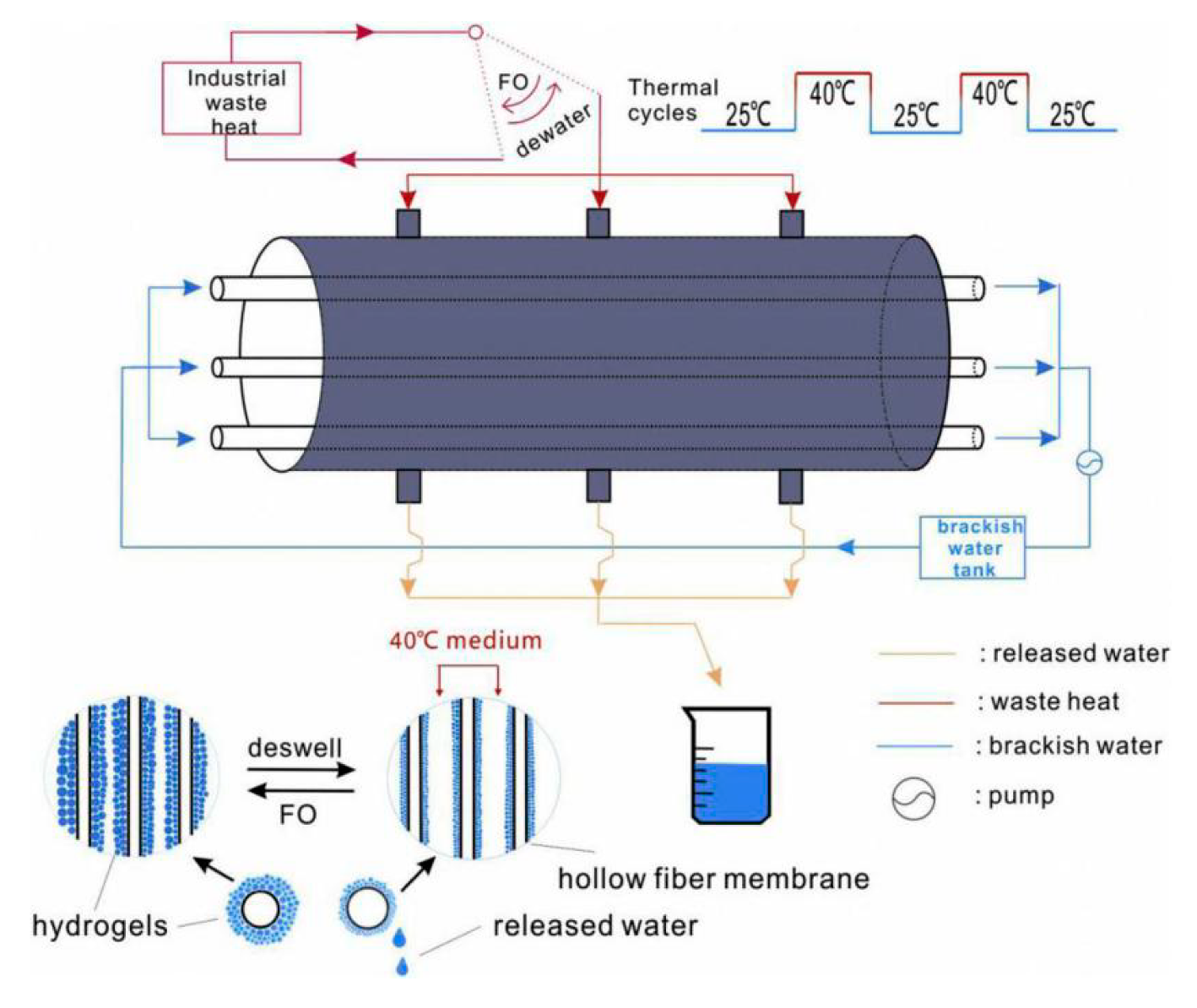
So far, the adsorption and de-adsorption process of hydrogel as the draw agent in the FO process occurred mostly in a batch mode. It not only increases the operating costs but also reduces the apparent water flux. Wang et al. for the first time proposed the bi-functional polymer hydrogel layers as FO draw agents for continuous production of the fresh water by using solar energy. There was no need to remove the draw agent from the membrane module, making it possible to continuously produce liquid fresh water [65]. However, the dewatering layer simply accumulates on the drawing layer. Besides, the reverse osmotic drive force from the second nonionic layer to the first ionic layer hindered the water molecules’ diffusion, resulting in the reduction of water flux. Subsequently, Chen et al. prepared a multi-layer temperature-responsive hydrogel based on poly(N-isopropylacrylamide-co-sodium acrylate) (P(NIPAAm-co-SA) [66]. The concentration of sodium acrylate decreased away from the FO membrane in the drawing layer, and the releasing layer was pure PNIPAm. The design can effectively decrease reverse osmotic pressure, resulting in the increase of water flux. Besides, the dehydrated layer was directly synthesized on the substrate of the drawing layer by free-radical polymerization of NIPAAm, forming a whole hydrogel (Figure 8). Research showed that the drawing layer determines the swelling capability and the releasing layer determines swelling kinetics due to the restriction in the expansion of the drawing layer. However, the upward bending of the hydrogel would affect its effective contact area with the membrane surface, since the releasing layer swelled at a lower rate compared to that of the drawing layer. Besides, the resistance of water molecules to the diffusion from the drawing layer to the releasing layer is unavoidable, and the effects of the gel swelling and FO membrane, which are not pre-infiltrated on the water flux, remain to study.
5. Some Important Issues
Although hydrogels have been investigated as draw agents for nine years, there are still some confusing issues that remain to be explained, such as the true driving force, high initial water flux but low apparent water flux, whether absolute clean water can be produced, and no draw solute reverse diffusion.
5.1. What on Earth Is It That Makes Hydrogel Produce Water Flux as the Draw Solute in the FO Process?
A series of hydrogels were evaluated as draw solutes for the FO process. However, the true driving force of hydrogels for producing water flux is unclear. There has been a discussion regarding the difference between swelling pressure and osmotic pressure [67,68].
Osmotic pressure is the minimum pressure to prevent the inward flow of water across a semipermeable membrane [69]. Osmotic pressure is a colligative property of a solution, depending on the dissociation number of solute molecules. Jacobus Van’t Hoff was the first person who proposed the equation interpreting the relationship of osmotic pressure, dissociation number of solute molecules, and thermodynamic temperature [69].
The osmotic pressure π of an ideal solution with low concentration can be calculated according to the Morse equation (Equation (1)) derived from the Van’t Hoff formula.
While a hydrogel is insoluble in water, the Morse equation cannot interpret the drive force of the hydrogel as draw solute in the FO process. Hydrogel osmotic pressure can be derived from the Flory-Huggins theory (Equations (3) and (4)) [70].
where R is the gas constant; T is the absolute temperature; V1 is the molar volume of solvent; λ is the mutual effect parameter of polymer and water; Φ0 and Φ are the volume before swell and after swell, respectively, Ngel and Nsol are the sum concentration of gel and solution, respectively, and V is the percentage of the gel network number of chains per volume when Φ0 is equal to Φ. In brief, the osmotic pressure accounts for the interaction of water and polymer (π1), elasticity force of the gel structure (π2), and the ion concentration difference inside and outside of the polymer networks (π3).
Tauer et al. suggested that hydrogel swelling pressure, ∆pswell, similar to the osmotic pressure, contributes to the equilibration of chemical potential between the outside and inside of the swollen gel and, respectively (Equation (5)) [71]. Here, νm,sa is the molar volume of the swelling agent in the gel. µ1o and µ1sg are the chemical potential of the swelling agent outside and inside the swollen gel when reaching at the swelling equilibration.
Wang et al. believed that swelling pressure was the true driving force for hydrogel draw solutes that originates from polymer-water mixing, elastic reaction force of the network, and osmotic pressure of ionizable groups (Equation (6)) [68].
where IItot is the swelling pressure of the gel, and IImix, IIel, and IIion are the mixing, elastic, and ionic contributions, respectively.
It is clear that the hydrogel osmotic pressure is in accordance with the swelling pressure defined by Wang et al. However, the hydrogel osmotic pressure corresponds to the difference of the water chemical potential between the inner and outer volumes of the hydrogel, which can be confirmed by the definition of the swelling pressure (Equation (5)), whereas the drive force for the forward osmosis process is the difference in osmotic pressures of the feed solution and that from the outer volume of the hydrogel. Therefore, swelling pressure is not the driving force of the hydrogel for FO. The true driving force comes from the hydration and ionization of the outer-side volume of the hydrogel.
5.2. Why the Initial Water Flux of Hydrogel as Draw Solute Is Considered High Whereas the Total Water Flux Is Close to Zero in the 24-h FO process?
To better explain this phenomenon, the swelling process, factors influencing swelling capability, and swelling dynamic will be discussed in detail.
5.2.1. The Swelling Procedure and the Principle of Water Absorption by Hydrogel
When dry polymer contacts with water, some amount of water is first absorbed by capillary absorption and physical diffusion, so that the hydrogel presents the initial slow expansion state. Subsequently, strong hydrophilic groups enhance the affinity to water by hydrogen bonds and the solvation effect, such as the amino group, carboxyl group, hydroxyl group, and especially, for polymers containing ionic groups. A large number of the same charges and counterions can be produced by ionization. However, the counterions cannot migrate freely outside of the gel in order to maintain electrical neutrality, which results in the enhancement of osmotic pressure, driving more water molecules into the polymer network. With the expansion of the network, the elastic contraction force caused by the crosslinking between molecular chains increases the limits of the infinite expansion of the network. Finally, the hydrogel achieves swelling equilibrium [72,73]. In this process, the osmotic pressure is the driving force for the expansion of swelling, and the network elastic force is the driving force for the contraction of a gel. Particularly, neither the capillary effect nor the hydration effect of hydrophilic groups can explain the main reason for why the water absorption by hydrogel materials can reach hundreds, even thousands, times their own weight. The amount of water absorbed by the capillary effect and hydrophilic group hydration effect differs by two to three orders of magnitude from that absorbed by the hydrogel materials. The main drive force for hydrogel swelling is the ion osmotic pressure. The principle of water absorption by the hydrogel can be illustrated by the Flory theory of ionic networks [74].
where Q is the maximum swelling ratio, i is the electronic charge of the polymer structure per polymer unit, Vu is the polymer repeating unit volume, i/Vu is the charge concentration of the charge fixed in resin, S is the ionic strength of solution, ν1 is the molar volume of solvent in a real network, χ1 is the interaction parameter of the polymer with solvent, (1/2-χ1)/V1 represents the affinity between water and the polymer electrolyte network, Ve represents the effective number of chains, V0 represents the volume of the polymer before swelling, and Ve/Vo represents the crosslinking degree.
The equation (Equation (7)) shows that the water absorption power mainly depends on the osmotic pressure, the affinity of the polymer to water, and the crosslinking density of the network.
5.2.2. Factors influencing Swelling Dynamic of Hydrogels
According to the swelling dynamic theory, the response rate of the hydrogel is proportional to the square of the size of the hydrogel and inversely proportional to the diffusion coefficient, as shown in Equation (8). Therefore, the response rate of the hydrogel can be improved by decreasing the hydrogel size and increasing the diffusion coefficient (D) [75].
T is the response time of a gel, D is the diffusion coefficient of a gel, and L is the characteristic size of a gel.
5.2.3. Explaining the High Initial Water Flux but Low Apparent Water Flux
According to the swelling procedure of the hydrogel, the outer-side of the hydrogel can produce high osmotic pressure by ionization and hydration effects, resulting in the high initial water flux [74]. The water was absorbed by the hydrogel due to the difference of chemical potential. However, the dilution rate is higher than the absorption rate due to the considerably high resistance and external concentration polarization (ECP), and hence, the driving force was further reduced [76]. Especially, the external osmotic pressure reached at minimum when the hydrogels achieve the swelling equilibrium. In addition, a dense skin layer is formed in the external layer of the bi-functional polymer hydrogel, which restrains the outward diffusion of water molecules during the hydrogel-collapse process at the temperatures above the LCST during the deswelling process [77]. Therefore, a low apparent water flux was produced.
5.3. Hydrogels Draw Solutes Have the Advantages of Intrinsically Zero Draw Solute Reverse Diffusion and There Is No Need to Further Polish the Released Water. Is it Actually True?
The hydrogels functioned with sodium acrylate or sodium sulfonate can release sodium ions to the produced water due to the ionization. Therefore, absolute zero draw solute reverse diffusion is impossible [55]. Moreover, the inner volume of the swelling hydrogel is full of sodium ion; then, the recovered water is not purely squeezed out from the hydrogel under a high external pressure combined with thermal influence. Further purification may be needed.
6. Challenges and Prospects for the Future
Desirable hydrogels as draw solutes are supposed to possess a high swelling rate, high deswelling rate with low cost, and high mechanical strength. Besides, the FO unit can be operated in continuous mode. Various methods have been applied to enhance the performance of hydrogels as draw solutes in the FO process. However, the apparent water flux is still low. The swelling rate and dewatering rate can also be enhanced by the following methods.
Since slow swelling of dried hydrogels is due to the slow diffusion of water into the glassy matrix of the dried hydrogels, introducing connected pores adding capillary action is conductive to the water diffusion [78,79]. Porous hydrogels can be prepared by a variety of methods, such as the porosigen technique [80], phase separation technique [81], crosslinking of individual hydrogel particles [82], and gas-blowing technique [83]. Besides, surface crosslinking can increase the modulus of the gel, while the friction coefficient between the polymer chain segment and solvent is basically unchanged, so the diffusion coefficient of the gel (D) also can be increased, according to the swelling dynamic of the hydrogel. Besides, surface crosslinking can effectively solve “case hardening” during the dewatering process [84]. Fabricating hydrogels with heterogeneous internal microstructures instead of homogeneous ones contributes to the formation of water release channels within the skin layer by chemically grafting linear hydrophilic side chains onto the hydrogel networks [78].
Although thermally responsiveness of the hydrogel is favorable for its regeneration in the FO process, the dewatering efficiency is still low [36]. Therefore, improving the dewatering efficiency is the key to enhancing the apparent water flux. A combination of external pressure and thermal can effectively improve the dewatering efficiency, but high mechanical strength is needed [36]. Shape memory polymers (SMPs) are capable of being fixed into a temporary shape upon programming and, subsequently, able to recover their original shape under appropriate external stimuli, such as heat [85]. The recover stress can reach 1.8 Mpa, and even more. Therefore, introducing a reversible bidirectional shape memory polymer (rbSME) to a thermally responsive hydrogel may be a good alternative to solve the dewatering problem.
Furthermore, we can design a semi-interpenetrating (semi-IPN) network of thermo-sensitive and conductive hybrid hydrogels to enhance dewatering efficiency [86]. The interpenetrating binary network structure provides hybrid hydrogels with continuous transporting pathways for electrons, highly porous microstructures, and strong interactions between two hydrogel networks, thus endowing the hybrid hydrogels with a unique combination of high electrical conductivity, high thermo-sensitivity, and greatly enhanced mechanical properties.
Further work is needed as none of the above-mentioned draw solutes is perfect. Designing draw solutes aims at a comprehensive balance between low energy consumption and easy fabrication. Tackling these challenges requires multidisciplinary efforts and knowledge in chemistry, materials science, and process engineering.
Author Contributions
Conceptualization, J.T. and J.W.; methodology, J.W.; software, S.G.; validation, J.T., W.S., and F.C.; formal analysis, S.G.; investigation, J.W.; resources, J.W.; data curation, J.W.; writing—original draft preparation, J.W.; writing—review and editing, J.T.; visualization, S.G.; supervision, W.S.; project administration, J.T., W.S., and F.C.; and funding acquisition, J.T. All authors have read and agreed to the published version of the manuscript.
Funding
This work was supported by the National Natural Science Foundation of China (No. 51908181 and No. 51678187), the Natural Science Foundation of Hebei Province (No. E2019202011 and No. E2019202012), the Natural Science Foundation of Tianjin (No. 19JCJQJC63000), and the Science and Technology Research Program for Colleges and Universities in Hebei Province (No. QN2019022).
Conflicts of Interest
The authors declare no conflicts of interest.
Abbreviations
| PAM | poly(acrylamide) |
| PNIPAm | poly(N-isopropylacrylamide) |
| PSA | poly(sodium acrylate) |
| PSA-NIPAm | poly(sodium acrylate)-N-isopropylacrylamide |
| NP | N-isopropylacrylamide |
| NP95-AAm5 | thermo-responsive copolymer microgels (the mass ratio of N-isopropylacrylamide and acrylamide is 95:5) |
| NP95-HEMA5 | thermo-responsive copolymer microgels (the mass ratio of N-isopropylacrylamide and 2-hydroxyethyl methacrylate is 95:5) |
| NP95-PEGA5 | thermo-responsive copolymer microgels (the mass ratio of N-isopropylacrylamide and poly (ethylene glycol) methyl ether acrylate is 95:5) |
| P(MT20EO80) | the copolymer of (2-(methactyloyloxy) ethyl) trimethylammonium chloride (MT) and 2-(2-methoxyethoxy) ethyl methacrylate (EO) (the mass ratio is 20:80) |
| PSSP5 | poly(tetrabuylphosphonium styrenesulfonates)5 |
| TVBP-C6-5/5 | tributyl-4-vinylbenzylphosphonium (TVBP)-C6-5/5 based poly(ionic liquid) hydrogels where six represents the number of carbon atoms in the alkane sulfonate counterion and 5/5 represents the molar ratio of PPG to PEG |
| MCG-NP | microgels-N-isopropylacrylamide |
| MCG-NP-MAA | microgels-N-isopropylacrylamide-methacrylic acid |
| MCG-NP-AA | microgels-N-isopropylacrylamide-acrylic acid |
| MCG-NP-MA | microgels-N-isopropylacrylamide-maleic acid |
| MCG-NP-IA | microgels-N-isopropylacrylamide-itaconic acid |
| MCG-NP-AMPS | microgels-N-isopropylacrylamide-2-acrylamido-2-methyl-1-propanesulfonic acid |
| MCG-NP-DMAEMA | microgels-N-isopropylacrylamide-2-acrylamido-2-methyl-1-propanesulfonic acid |
| MCG-NP-DEAEMA | microgels-N-isopropylacrylamide-2-(diethylamino) ethyl methacrylate |
| MCG-NP-VP | microgels-N-isopropylacrylamide-4-vinylpyridine |
| MCG-NP-VI | microgels-N-isopropylacrylamide-1-vinylimidazole |
| CMC-g-PNaA-co-PNIPAM | carboxymethyl cellulose-graft-poly (sodium acrylate)-copolymerization-N-isopropylacrylamide |
| PSA-C | poly(sodium acrylate)-carbon |
| PNIPAM-C | poly(N-isopropylacrylamide)-carbon |
| PSA- NIPAM-C | poly(sodium acrylate)-N-isopropylacrylamide-carbon |
| PSA-1.2 wt% rGO | poly(sodium acrylate)-1.2wt% reduced graphene oxide |
| PSA-NIPAM-1.2 wt% rGO | Composite polymer hydrogel synthesized by adding 1.2wt% reduced graphene oxide, sodium acrylate and N-isopropylacrylamide |
| PSA-NIPAM-16 wt% γ-Fe2O3 | Composite polymer hydrogel synthesized by adding 16wt% γ-iron(III) oxide nanoparticles, sodium acrylate and N-isopropylacrylamide |
| PNIPAm-PSA-PUF | poly(N-isopropylacrylamide)-poly(sodium acrylate)-polyurethane |
| TPU-PN5S5 | thermoplastic polyurethane-N-isopropylacrylamide-sodium acrylate |
| SI-0.2PSA | semi-IPN-0.2 poly(sodium acrylate) |
| SI-0.5PVA | semi-IPN-0.5 polyvinyl alcohol |
| PEG-PLGA-PEG | poly(ethylene glycol-[DL-lactic acid-co-glycolic acid]-b-ethylene glycol) |
| PEG-PLGA-PEG/GO | poly(ethylene glycol-[DL-lactic acid-co-glycolic acid]-b-ethylene glycol)/Graphene oxide |
| PEG-PLGA-PEG/G | poly(ethylene glycol-[DL-lactic acid-co-glycolic acid]-b-ethylene glycol)/Graphene 5PSA-C-150 |
| PSA-C | poly(sodium acrylate)-carbon |
| MCG-NP-AA | microgel-N-isopropylacrylamide-acid acrylate |
| HA-PVA | Hyaluronic acid-Poly(vinyl alcohol) |
| AMPS/DMAEMA | 2-Acrylamido-2-methyl-1-propanesulfonic acid /2-N,N′-(Dimethylamino)ethyl methacrylate |
| DEAEMA-PEGDA | 2-N,N′-(diethylamino)ethyl methacrylate-poly (ethylene glycol diacrylate) |
| DMAEMA-PEGDA | 2-N,N′-(dimethylamino) ethyl methacrylate (DMAEMA)-poly (ethylene glycol diacrylate) |
| Fe3O4@P(NIPAM-co-AMPS) | Fe3O4@P(N-isopropylacrylamide-copolymerization-sodium 2-acrylamido-2-methylpropane sulfonate) |
| SL | single-layer |
| BL | bi-layer |
| ML | multi-layer |
References
- Klaysom, C.; Cath, T.Y.; Depuydt, T.; Vankelecom, I.F. Forward and pressure retarded osmosis: Potential solutions for global challenges in energy and water supply. Chem. Soc. Rev. 2013, 42, 6959–6989. [Google Scholar] [CrossRef]
- Zhao, D.; Qiu, G.; Li, X.; Wan, C.; Lu, K.; Chung, T.S. Zwitterions coated hollow fiber membranes with enhanced antifouling properties for osmotic power generation from municipal wastewater. Water Res. 2016, 104, 389–396. [Google Scholar] [CrossRef]
- Zhao, Q.; Chen, N.; Zhao, D.; Lu, X. Thermoresponsive magnetic nanoparticles for seawater desalination. ACS Appl. Mater. Interfaces 2013, 5, 11453–11461. [Google Scholar] [PubMed]
- Elimelech, M.; Wiesner, M.R. Membrane Separations in Aquatic Systems. Environ. Eng. Sci. 2002, 19, 341. [Google Scholar] [CrossRef]
- Humplik, T.; Lee, J.; O’Hern, S.C.; Fellman, B.A.; Baig, M.A.; Hassan, S.F.; Atieh, M.A.; Rahman, F.; Laoui, T.; Karnik, R.; et al. Nanostructured materials for water desalination. Nanotechnology 2011, 22, 292001. [Google Scholar] [CrossRef] [PubMed]
- Malaeb, L.; Ayoub, G.M. Reverse osmosis technology for water treatment: State of the art review. Desalination 2011, 267, 1–8. [Google Scholar] [CrossRef]
- Cath, T.; Childress, A.; Elimelech, M. Forward osmosis: Principles, applications, and recent developments. J. Membr. Sci. 2006, 281, 70–87. [Google Scholar] [CrossRef]
- Bao, X.; Wu, Q.; Shi, W.; Wang, W.; Yu, H.; Zhu, Z.; Cui, F. Polyamidoamine dendrimer grafted forward osmosis membrane with superior ammonia selectivity and robust antifouling capacity for domestic wastewater concentration. Water Res. 2019, 153, 1–10. [Google Scholar] [CrossRef]
- Bao, X.; Wu, Q.; Shi, W.; Wang, W.; Zhu, Z.; Zhang, Z.; Cui, F. Dendritic amine sheltered membrane for simultaneous ammonia selection and fouling mitigation in forward osmosis. J. Membr. Sci. 2019, 584, 9–19. [Google Scholar] [CrossRef]
- Bao, X.; Wu, Q.; Tian, J.; Shi, W.; Wang, W.; Zhang, Z.; Cui, F. Fouling mechanism of forward osmosis membrane in domestic wastewater concentration: Role of substrate structures. Chem. Eng. J. 2019, 370, 262–273. [Google Scholar]
- Zhang, X.; Tian, J.; Gao, S.; Shi, W.; Zhang, Z.; Cui, F.; Liu, D. Surface functionalization of TFC FO membranes with zwitterionic polymers: Improvement of antifouling and salt-responsive cleaning properties. J. Membr. Sci. 2017, 544, 368–377. [Google Scholar] [CrossRef]
- Zhang, X.; Tian, J.; Gao, S.; Zhang, Z.; Cui, F.; Tang, C.Y. In situ surface modification of thin film composite forward osmosis membranes with sulfonated poly (arylene ether sulfone) for anti-fouling in emulsified oil/water separation. J. Membr. Sci. 2017, 527, 26–34. [Google Scholar] [CrossRef]
- Zhang, X.; Tian, J.; Ren, Z.; Shi, W.; Zhang, Z.; Xu, Y.; Cui, F. High performance thin-film composite (TFC) forward osmosis (FO) membrane fabricated on novel hydrophilic disulfonated poly (arylene ether sulfone) multiblock copolymer/polysulfone substrate. J. Membr. Sci. 2016, 520, 529–539. [Google Scholar] [CrossRef]
- Qasim, M.; Darwish, N.A.; Sarp, S.; Hilal, N. Water desalination by forward (direct) osmosis phenomenon: A comprehensive review. Desalination 2015, 374, 47–69. [Google Scholar] [CrossRef]
- Werner, C.M.; Logan, B.E.; Saikaly, P.E.; Amy, G.L. Wastewater treatment, energy recovery and desalination using a forward osmosis membrane in an air-cathode microbial osmotic fuel cell. J. Membr. Sci. 2013, 428, 116–122. [Google Scholar] [CrossRef]
- McCutcheon, J.R.; McGinnis, R.L.; Elimelech, M. Desalination by ammonia–carbon dioxide forward osmosis: Influence of draw and feed solution concentrations on process performance. J. Membr. Sci. 2006, 278, 114–123. [Google Scholar] [CrossRef]
- She, Q.; Jin, X.; Tang, C.Y. Osmotic power production from salinity gradient resource by pressure retarded osmosis: Effects of operating conditions and reverse solute diffusion. J. Membr. Sci. 2012, 401–402, 262–273. [Google Scholar] [CrossRef]
- Ling, M.M.; Chung, T.S. Novel dual-stage FO system for sustainable protein enrichment using nanoparticles as intermediate draw solutes. J. Membr. Sci. 2011, 372, 201–209. [Google Scholar] [CrossRef]
- Dova, M.I.; Petrotos, K.B.; Lazarides, H.N. On the direct osmotic concentration of liquid foods. Part I: Impact of process parameters on process performance. J. Food Eng. 2007, 78, 422–430. [Google Scholar] [CrossRef]
- Akther, N.; Sodiq, A.; Giwa, A.; Daer, S.; Arafat, H.A.; Hasan, S.W. Recent advancements in forward osmosis desalination: A review. Chem. Eng. J. 2015, 281, 502–522. [Google Scholar] [CrossRef]
- Phuntsho, S.; Shon, H.K.; Hong, S.; Lee, S.; Vigneswaran, S. A novel low energy fertilizer driven forward osmosis desalination for direct fertigation: Evaluating the performance of fertilizer draw solutions. J. Membr. Sci. 2011, 375, 172–181. [Google Scholar] [CrossRef]
- Petrotos, K.B.; Quantick, P.; Petropakis, H. A study of the direct osmotic concentration of tomato juice in tubular membrane-module configuration. I. The effect of certain basic process parameters on the process performance. J. Membr. Sci. 1998, 150, 99–110. [Google Scholar] [CrossRef]
- Chekli, L.; Phuntsho, S.; Shon, H.K.; Vigneswaran, S.; Kandasamy, J.; Chanan, A. A review of draw solutes in forward osmosis process and their use in modern applications. Desalin. Water Treat. 2012, 43, 167–184. [Google Scholar] [CrossRef]
- Yokozeki, A. Osmotic pressures studied using a simple equation-of-state and its applications. Appl. Energy 2006, 83, 15–41. [Google Scholar] [CrossRef]
- Zhao, S.; Zou, L.; Tang, C.Y.; Mulcahy, D. Recent developments in forward osmosis: Opportunities and challenges. J. Membr. Sci. 2012, 396, 1–21. [Google Scholar] [CrossRef]
- Zydney, A.L. Stagnant film model for concentration polarization in membrane systems. J. Membr. Sci. 1997, 130, 275–281. [Google Scholar] [CrossRef]
- Gray, G.T.; McCutcheon, J.R.; Elimelech, M. Internal concentration polarization in forward osmosis: Role of membrane orientation. Desalination 2006, 197, 1–8. [Google Scholar] [CrossRef]
- Gao, Y.; Wang, Y.N.; Li, W.; Tang, C.Y. Characterization of internal and external concentration polarizations during forward osmosis processes. Desalination 2014, 338, 65–73. [Google Scholar] [CrossRef]
- Phillip, W.A.; Yong, J.S.; Elimelech, M. Reverse draw solute permeation in forward osmosis: Modeling and experiments. Environ. Sci. Technol. 2010, 44, 5170–5176. [Google Scholar] [CrossRef]
- Luo, H.; Wang, Q.; Zhang, T.C.; Tao, T.; Zhou, A.; Chen, L.; Bie, X. A review on the recovery methods of draw solutes in forward osmosis. J. Water Process Eng. 2014, 4, 212–223. [Google Scholar] [CrossRef]
- Gu, B.; Kim, J.H.; Yang, D.R. Theoretical analysis of a seawater desalination process integrating forward osmosis, crystallization, and reverse osmosis. J. Membr. Sci. 2013, 444, 440–448. [Google Scholar] [CrossRef]
- Chung, T.-S.; Li, X.; Ong, R.C.; Ge, Q.; Wang, H.; Han, G. Emerging forward osmosis (FO) technologies and challenges ahead for clean water and clean energy applications. Curr. Opin. Chem. Eng. 2012, 1, 246–257. [Google Scholar] [CrossRef]
- Ron, E.S.; Bromberg, L.E. Temperature-responsive gels and thermogelling polymer matrices for protein and peptide delivery. Adv. Drug Deliv. Rev. 1998, 31, 197–221. [Google Scholar] [PubMed]
- Lin, C.C.; Metters, A.T. Hydrogels in controlled release formulations: Network design and mathematical modeling. Adv. Drug Deliv. Rev. 2006, 58, 1379–1408. [Google Scholar] [CrossRef] [PubMed]
- Cai, Y.; Hu, X.M. A critical review on draw solutes development for forward osmosis. Desalination 2016, 391, 16–29. [Google Scholar] [CrossRef]
- Li, D.; Zhang, X.; Yao, J.; Simon, G.P.; Wang, H. Stimuli-responsive polymer hydrogels as a new class of draw agent for forward osmosis desalination. Chem. Commun. 2011, 47, 1710–1712. [Google Scholar] [CrossRef]
- Qiu, X.P.; Tanaka, F.; Winnik, F.M. Temperature-induced phase transition of well-defined cyclic poly (N-isopropylacrylamide) s in aqueous solution. Macromolecules 2007, 40, 7069–7071. [Google Scholar] [CrossRef]
- Hirose, Y.; Amiya, T.; Hirokawa, Y.; Tanaka, T. Phase transition of submicron gel beads. Macromolecules 1987, 20, 1342–1344. [Google Scholar] [CrossRef]
- Hartanto, Y.; Zargar, M.; Cui, X.; Jin, B.; Dai, S. Non-ionic copolymer microgels as high-performance draw materials for forward osmosis desalination. J. Membr. Sci. 2019, 572, 480–488. [Google Scholar] [CrossRef]
- Kim, J.J.; Chung, J.-S.; Kang, H.; Yu, Y.A.; Choi, W.J.; Kim, H.J.; Lee, J.-C. Thermo-responsive copolymers with ionic group as novel draw solutes for forward osmosis processes. Macromol. Res. 2014, 22, 963–970. [Google Scholar] [CrossRef]
- Kim, J.J.; Kang, H.; Choi, Y.-S.; Yu, Y.A.; Lee, J.C. Thermo-responsive oligomeric poly(tetrabutylphosphonium styrenesulfonate)s as draw solutes for forward osmosis (FO) applications. Desalination 2016, 381, 84–94. [Google Scholar] [CrossRef]
- Fan, X.; Liu, H.; Gao, Y.; Zou, Z.; Craig, V.S.; Zhang, G.; Liu, G. Forward-Osmosis Desalination with Poly(Ionic Liquid) Hydrogels as Smart Draw Agents. Adv. Mater. 2016, 28, 4156–4161. [Google Scholar] [CrossRef] [PubMed]
- Cai, Y.; Shen, W.; Loo, S.L.; Krantz, W.B.; Wang, R.; Fane, A.G.; Hu, X. Towards temperature driven forward osmosis desalination using Semi-IPN hydrogels as reversible draw agents. Water Res. 2013, 47, 3773–3781. [Google Scholar] [CrossRef] [PubMed]
- Hartanto, Y.; Zargar, M.; Wang, H.; Jin, B.; Dai, S. Thermoresponsive Acidic Microgels as Functional Draw Agents for Forward Osmosis Desalination. Environ. Sci. Technol. 2016, 50, 4221–4228. [Google Scholar] [CrossRef] [PubMed]
- Hartanto, Y.; Zargar, M.; Cui, X.; Shen, Y.; Jin, B.; Dai, S. Thermoresponsive cationic copolymer microgels as high performance draw agents in forward osmosis desalination. J. Membr. Sci. 2016, 518, 273–281. [Google Scholar] [CrossRef]
- Gawande, N.; Mungray, A.A. Superabsorbent polymer (SAP) hydrogels for protein enrichment. Sep. Purif. Technol. 2015, 150, 86–94. [Google Scholar] [CrossRef]
- Wei, J.; Low, Z.X.; Ou, R.; Simon, G.P.; Wang, H. Hydrogel-polyurethane interpenetrating network material as an advanced draw agent for forward osmosis process. Water Res. 2016, 96, 292–298. [Google Scholar] [CrossRef]
- Ou, R.; Zhang, H.; Simon, G.P.; Wang, H. Microfiber-polymer hydrogel monolith as forward osmosis draw agent. J. Membr. Sci. 2016, 510, 426–436. [Google Scholar] [CrossRef]
- Li, D.; Zhang, X.; Simon, G.P.; Wang, H. Forward osmosis desalination using polymer hydrogels as a draw agent: Influence of draw agent, feed solution and membrane on process performance. Water Res. 2013, 47, 209–215. [Google Scholar] [CrossRef] [Green Version]
- Razmjou, A.; Simon, G.P.; Wang, H. Effect of particle size on the performance of forward osmosis desalination by stimuli-responsive polymer hydrogels as a draw agent. Chem. Eng. J. 2013, 215–216, 913–920. [Google Scholar] [CrossRef]
- Hartanto, Y.; Yun, S.; Jin, B.; Dai, S. Functionalized thermo-responsive microgels for high performance forward osmosis desalination. Water Res. 2015, 70, 385–393. [Google Scholar] [CrossRef] [PubMed] [Green Version]
- Razmjou, A.; Barati, M.R.; Simon, G.P.; Suzuki, K.; Wang, H. Fast deswelling of nanocomposite polymer hydrogels via magnetic field-induced heating for emerging FO desalination. Environ. Sci. Technol. 2013, 47, 6297–6305. [Google Scholar] [CrossRef] [PubMed]
- Li, D.; Zhang, X.; Yao, J.; Zeng, Y.; Simon, G.P.; Wang, H. Composite polymer hydrogels as draw agents in forward osmosis and solar dewatering. Soft Matter 2011, 7, 10048–10056. [Google Scholar] [CrossRef]
- Zeng, Y.; Qiu, L.; Wang, K.; Yao, J.; Li, D.; Simon, G.P.; Wang, R.; Wang, H. Significantly enhanced water flux in forward osmosis desalination with polymer-graphene composite hydrogels as a draw agent. RSC Adv. 2013, 3, 887–894. [Google Scholar] [CrossRef]
- Debord, J.D.; Lyon, L.A. Synthesis and characterization of pH-responsive copolymer microgels with tunable volume phase transition temperatures. Langmuir 2003, 19, 7662–7664. [Google Scholar] [CrossRef]
- Hirose, H.; Shibayama, M. Kinetics of volume phase transition in poly (N-isopropylacrylamide-co-acrylic acid) gels. Macromolecules 1998, 31, 5336–5342. [Google Scholar] [CrossRef]
- Dragan, E.S. Design and applications of interpenetrating polymer network hydrogels. A review. Chem. Eng. J. 2014, 243, 572–590. [Google Scholar] [CrossRef]
- Pound, G.; Aguesse, F.; McLeary, J.B.; Lange, R.F.M.; Klumperman, B. Xanthate-Mediated Copolymerization of Vinyl Monomers for Amphiphilic and Double-Hydrophilic Block Copolymers with Poly(ethylene glycol). Macromolecules 2007, 40, 8861–8871. [Google Scholar] [CrossRef]
- Nakka, R.; Mungray, A.A. Biodegradable and biocompatible temperature sensitive triblock copolymer hydrogels as draw agents for forward osmosis. Sep. Purif. Technol. 2016, 168, 83–92. [Google Scholar] [CrossRef]
- Zhang, H.; Li, J.; Cui, H.; Li, H.; Yang, F. Forward osmosis using electric-responsive polymer hydrogels as draw agents: Influence of freezing–thawing cycles, voltage, feed solutions on process performance. Chem. Eng. J. 2015, 259, 814–819. [Google Scholar] [CrossRef]
- Juodkazytė, J.; Seniutinas, G.; Šebeka, B. Solar water splitting: Efficiency discussion. Int. J. Hydrogen Energy 2016, 41, 11941–11948. [Google Scholar] [CrossRef]
- Cui, H.; Zhang, H.; Yu, M.; Yang, F. Performance evaluation of electric-responsive hydrogels as draw agent in forward osmosis desalination. Desalination 2018, 426, 118–126. [Google Scholar] [CrossRef]
- Rabiee, H.; Jin, B.; Yun, S.; Dai, S. Gas-responsive cationic microgels for forward osmosis desalination. Chem. Eng. J. 2018, 347, 424–431. [Google Scholar] [CrossRef]
- Zhou, A.; Luo, H.; Wang, Q.; Chen, L.; Zhang, T.C.; Tao, T. Magnetic thermoresponsive ionic nanogels as novel draw agents in forward osmosis. RSC Adv. 2015, 5, 15359–15365. [Google Scholar] [CrossRef]
- Razmjou, A.; Liu, Q.; Simon, G.P.; Wang, H. Bifunctional polymer hydrogel layers as forward osmosis draw agents for continuous production of fresh water using solar energy. Environ. Sci. Technol. 2013, 47, 13160–13166. [Google Scholar] [CrossRef]
- Zeng, J.; Cui, S.; Wang, Q.; Chen, R. Multi-layer temperature-responsive hydrogel for forward-osmosis desalination with high permeable flux and fast water release. Desalination 2019, 459, 105–113. [Google Scholar] [CrossRef]
- Zhao, S. Osmotic pressure versus swelling pressure: Comment on “bifunctional polymer hydrogel layers as forward osmosis draw agents for continuous production of fresh water using solar energy”. Environ. Sci. Technol. 2014, 48, 4212–4213. [Google Scholar] [CrossRef]
- Wang, H.; Wei, J.; Simon, G.P. Response to osmotic pressure versus swelling pressure: Comment on “bifunctional polymer hydrogel layers as forward osmosis draw agents for continuous production of fresh water using solar energy”. Environ. Sci. Technol. 2014, 48, 4214–4215. [Google Scholar] [CrossRef]
- Hildebrand, J.H. Osmotic Pressure. Science 1955, 121, 116–119. [Google Scholar] [CrossRef]
- Wack, H.; Ulbricht, M. Effect of synthesis composition on the swelling pressure of polymeric hydrogels. Polymer 2009, 50, 2075–2080. [Google Scholar] [CrossRef]
- Höhne, P.; Tauer, K. How much weighs the swelling pressure. Colloid Polym. Sci. 2014, 292, 2983–2992. [Google Scholar] [CrossRef] [Green Version]
- Horkay, F.; Tasaki, I.; Basser, P.J. Osmotic swelling of polyacrylate hydrogels in physiological salt solutions. Biomacromolecules 2000, 1, 84–90. [Google Scholar] [CrossRef]
- Tanaka, T.; Fillmore, D. Kinetics of swelling of gels. J. Chem. Phys. 1979, 70, 1214–1218. [Google Scholar] [CrossRef]
- Laftah, W.A.; Hashim, S.; Ibrahim, A.N. Polymer Hydrogels: A Review. Polymer-Plast. Technol. Eng. 2011, 50, 1475–1486. [Google Scholar] [CrossRef]
- Fujiyabu, T.; Yoshikawa, Y.; Chung, U.I.; Sakai, T. Structure-property relationship of a model network containing solvent. Sci. Technol. Adv. Mater. 2019, 20, 608–621. [Google Scholar] [CrossRef] [PubMed] [Green Version]
- Mudiyanselage, T.K.; Neckers, D.C. Highly absorbing superabsorbent polymer. J. Polym. Sci. Part A Polym. Chem. 2008, 46, 1357–1364. [Google Scholar] [CrossRef]
- Zhang, X.; Xu, X.; Cheng, S.; Zhuo, R. Strategies to improve the response rate of thermosensitive PNIPAAm hydrogels. Soft Matter. 2008, 4, 385–391. [Google Scholar] [CrossRef]
- Okeyoshi, K.; Abe, T.; Noguchi, Y.; Furukawa, H.; Yoshida, R. Shrinking Behavior of Surfactant-Grafted Thermosensitive Gels and the Mechanism of Rapid Shrinking. Macromol. Rapid Commun. 2008, 29, 897–903. [Google Scholar] [CrossRef]
- Chen, J.; Park, H.; Park, K. Synthesis of superporous hydrogels: Hydrogels with fast swelling and superabsorbent properties. J. Biomed. Mater. Res. 1999, 44, 53–62. [Google Scholar] [CrossRef]
- Lee, W.F.; Yeh, Y.C. Effect of porosigen and hydrophobic monomer on the fast swelling-deswelling behaviors for the porous thermoreversible copolymeric hydrogels. J. Appl. Polym. Sci. 2006, 100, 3152–3160. [Google Scholar] [CrossRef]
- Chirila, T.V.; Constable, I.J.; Crawford, G.J.; Vijayasekaran, S.; Thompson, D.E.; Chen, C.; Fletcher, W.A. Poly (2-hydroxyethyl methacrylate) sponges as implant materials: In vivo and in vitro evaluation of cellular invasion. Biomaterials 1993, 14, 26–38. [Google Scholar] [CrossRef]
- Chang, S.; Kim, M.; Oh, S. Multi-scale characterization of surface-crosslinked superabsorbent polymer hydrogel spheres. Polymer 2018, 145, 174–183. [Google Scholar] [CrossRef]
- Gemeinhart, R.A.; Park, H. Pore structure of superporous hydrogels. Polym. Adv. Technol. 2000, 11, 617–625. [Google Scholar] [CrossRef]
- Khalloufi, S.; Bongers, P. Mathematical investigation of the case hardening phenomenon explained by shrinkage and collapse mechanisms occurring during drying processes. Comput. Aided Chem. Eng. 2012, 30, 1068–1072. [Google Scholar]
- Xie, T. Tunable polymer multi-shape memory effect. Nature 2010, 464, 267–270. [Google Scholar] [CrossRef]
- Shi, Y.; Ma, C.; Peng, L. Conductive “Smart” Hybrid Hydrogels with PNIPAM and Nanostructured Conductive Polymers. Adv. Funct. Mater. 2015, 25, 1219–1225. [Google Scholar] [CrossRef]
Figure 1.
Schematic representation of the reverse osmosis process (a) and forward osmosis process (b).
Figure 1.
Schematic representation of the reverse osmosis process (a) and forward osmosis process (b).

Figure 2.
An asymmetric dense membrane with the porous support layer facing the feed solution (a) and draw solution (b). The profile illustrates concentration polarization, respectively. CECP: concentrative external concentration polarization, CICP: concentrative internal concentration polarization, DECP: dilutive external concentration polarization and DICP dilutive internal concentration polarization, Δπm: the osmotic pressure difference between concentrative feed (C2) and dilutive draw solution (C4) on both outer sides of the forward osmosis membrane, Δπbulk the osmotic pressure difference between feed (C1)and draw solution (C5), Δπeff: the effective osmotic pressure difference between further concentrative feed (C3) and dilutive draw solution (C4) on both sides of the active layer, C (1–5): the concentration of solution in different positions.

Figure 3.
Schematic representation of the polymer hydrogel-forward osmosis desalination process. Reprinted from Reference [36] with permission from The Royal Society of Chemistry.
Figure 3.
Schematic representation of the polymer hydrogel-forward osmosis desalination process. Reprinted from Reference [36] with permission from The Royal Society of Chemistry.

Figure 4.
Semi-logarithmic plot of the effect of particle sizes on the swelling ratio of 0.1 g N-isopropylacrylamide-sodium acrylate (NIPAM-SA) hydrogels (a), and the schematic illustration of the interstitial volume in small and large hydrogel particles (b). Reprinted from Reference [50] with permission from Elsevier.

Figure 5.
Schematic diagram of the effect of magnetic and conventional heating on the dewatering of nanocomposite polymer hydrogels being used as draw agents in the forward osmosis (FO) process. Reprinted from Reference [52] with permission from the ACS Journal.
Figure 5.
Schematic diagram of the effect of magnetic and conventional heating on the dewatering of nanocomposite polymer hydrogels being used as draw agents in the forward osmosis (FO) process. Reprinted from Reference [52] with permission from the ACS Journal.

Figure 6.
Quasi-continuous forward osmosis (FO) desalination using a semi-interpenetrating network (IPN) hydrogel as the draw agent. Reprinted from Reference [43] with permission from Elsevier.
Figure 6.
Quasi-continuous forward osmosis (FO) desalination using a semi-interpenetrating network (IPN) hydrogel as the draw agent. Reprinted from Reference [43] with permission from Elsevier.

Figure 7.
Schematic representation of the forward osmosis (FO) desalination process considering hyaluronic acid-poly(vinyl alcohol) (HA-PVA) polymer hydrogels as the draw agents. Reprinted from Reference [60] with permission from Elsevier.
Figure 7.
Schematic representation of the forward osmosis (FO) desalination process considering hyaluronic acid-poly(vinyl alcohol) (HA-PVA) polymer hydrogels as the draw agents. Reprinted from Reference [60] with permission from Elsevier.

Figure 8.
Schematic of continuous semi-batch FO process using bilayer thermo-responsive hydrogels as the draw agent. Reprinted from Reference [66] with permission from Elsevier. LCST: lower critical solution temperature.
Figure 8.
Schematic of continuous semi-batch FO process using bilayer thermo-responsive hydrogels as the draw agent. Reprinted from Reference [66] with permission from Elsevier. LCST: lower critical solution temperature.


Table 1.
Summary of various types of hydrogels as draw solutes in the forward osmosis (FO) process.
| Draw Solution | De-Watering Method | FO Performance | Ref. | |
|---|---|---|---|---|
| Initial Flux (L/m2h) | Water Recovery | |||
| PAM | Heating at 50 °C | 0.36 (1st h) | <10% | [36] |
| PNIPAm | 0.30 (1st h) | 54%–75% | ||
| PSA | 0.96 (1st h) | <5% | ||
| PSA-NIPAm | 0.55 (1st h) | 17% | ||
| NP | Centrifuged at 40 °C and 10,000 rpm for 10 min | 5.1 | 83.3% | [39] |
| NP95-AAm5 | 24.7 | 78.7% | ||
| NP95-HEMA5 | 7.8 | 88.9% | ||
| NP95-PEGA5 | 6.4 | 89.1% | ||
| P(MT20EO80) | Heating at 70 °C followed by microfiltration process | - | 99.7% | [40] |
| PSSP5 | Heating at 60 °C | - | 99.5% | [41] |
| TVBP-C6-5/5 | Heating at 60 °C | < 0.9 | <90% | [42] |
| SI-0.2PSA | Heating at 40 °C for 10 min | 0.18 (1st h) | - | [43] |
| SI-0.5PVA | 0.18 (1st h) | |||
| SI-0.2PVA | 0.12 (1st h) | |||
| MCG-NP | Centrifuged at 40 °C and 10,000 rpm for 10 min | 7.5 (1st min) | 72.1% | [44] |
| MCG-NP-MAA | 10.9 (1st min) | 76.7% | ||
| MCG-NP-AA | 16.7 (1st min) | 55.8% | ||
| MCG-NP-MA | 39.1 (1st min) | 39.1% | ||
| MCG-NP-IA | 44.8 (1st min) | 47.2% | ||
| MCG-NP-AMPS | 42.9 (1st min) | 0% | ||
| MCG-NP-DMAEMA | Centrifuged at 40 °C and 10,000 rpm for 10 min | 33.5 (1st min) | 34.1% | [45] |
| MCG-NP-DEAEMA | 45.6 (1st min) | 44.8% | ||
| MCG-NP-VP | 17.3 (1st min) | 51.9% | ||
| MCG-NP-VI | 28.9 (1st min) | 47.9% | ||
| CMC-g-PNaA-co-PNIPAM | - | - | 70% | [46] |
| PNIPAm-PSA-PUF (mass ration, 8:1) | Under sunlight simulator (2 kw/m2) | 14.8 | 100% | [47] |
| TPU-PN5S5 | Under sunlight simulator (1 kw/m2) | 1.81 (10st min) | - | [48] |
| TPU-PN5S5 | 2.77 (10st min) | |||
| 5PSA-C-150 100–200 um | - | 1.02 | - | [49] |
| PSA-C-150 100–200 um | - | 1.06 | - | |
| PSA-5C-150 100–200 um | - | 1.06 | - | |
| PSA-NIPAm (2–25 um) | N2 gas pressure of 600 kPa for 15 min | - | <7% (swelling ratio 10) | [50] |
| PSA-NIPAm (190–350 um) | - | <5% (swelling ratio 10) | ||
| PSA-NIPAm (500–1000 um) | - | - | ||
| MCG-NP100-AA0 | - | 2 (10st min) | - | [51] |
| MCG-NP50-AA50 | - | 4 (10st min) | - | |
| PSA-NIPAM-16 wt%γ-Fe2O3 | Magnetic AC field (148 kOe and 372 kHz) | <2.5 (1.0st h) | 66% | [52] |
| PSA-C | Under the sunlight simulator (1 kw m−2) | 1.32 (0.5st h) | 70.4% | [53] |
| PNIPAM-C | 0.44 (0.5st h) | 100% | ||
| PSA- NIPAM-C | 0.77 (0.5st h) | 100% | ||
| PSA-1.2 wt% rGO | Under the sunlight simulator (1 kW m−2) for 1h | 3.1 (1.0st h) | 42% | [54] |
| PSA-NIPAM-1.2 wt% rGO | 0.9 (1.0st h) | 45% | ||
| PEG-PLGA-PEG | 13,000 rpm for 10 min | - | 98% | [59] |
| PEG-PLGA-PEG/GO-0.09 wt% | - | 98% | ||
| PEG-PLGA-PEG/G-0.09 wt% | - | 98% | ||
| HA-PVA-5 | Electric field (9 v) | 1.2 | [60] | |
| HA-PVA-7 | 0.91 | |||
| HA-PVA-9 | 0.9 | |||
| AMPS/DMAEMA (0.55/0.45) | Electric field (15 v) for 60 min | 2.09 (1st h) | 67.45% | [62] |
| AMPS/DMAEMA (0.53/0.47) | 1.63 (1st h) | 39.36% | ||
| DEAEMA-PEGDA (1 wt%) | Puring N2 | 56 (10st min) | 55% | [63] |
| DMAEMA-PEGDA (1 wt%) | 41 (10st min) | 44% | ||
| Fe3O4@P(NIPAM-co-AMPS) | 65 °C and magnetic field (250 mT) | 0.26 (20st min) | [64] | |
| PNIPAm-PSA (mass ration, 1:1) | Solar energy of 0.5 kW m−2 for 1 h | 0.25 (20st min) | 7.8% ± 1.5% | [65] |
| SL-2 | Heating at 60 °C f or 120 min | 0.191 (1st h) | [66] | |
| BL-2 | 0.236 (1st h) | 72% | ||
| ML-1 | 0.292 (1st h) | |||
Note: st stands for first.
© 2020 by the authors. Licensee MDPI, Basel, Switzerland. This article is an open access article distributed under the terms and conditions of the Creative Commons Attribution (CC BY) license (http://creativecommons.org/licenses/by/4.0/).
Share and Cite
MDPI and ACS Style
Wang, J.; Gao, S.; Tian, J.; Cui, F.; Shi, W. Recent Developments and Future Challenges of Hydrogels as Draw Solutes in Forward Osmosis Process. Water 2020, 12, 692. https://doi.org/10.3390/w12030692
AMA Style
Wang J, Gao S, Tian J, Cui F, Shi W. Recent Developments and Future Challenges of Hydrogels as Draw Solutes in Forward Osmosis Process. Water. 2020; 12(3):692. https://doi.org/10.3390/w12030692
Chicago/Turabian StyleWang, Jichao, Shanshan Gao, Jiayu Tian, Fuyi Cui, and Wenxin Shi. 2020. "Recent Developments and Future Challenges of Hydrogels as Draw Solutes in Forward Osmosis Process" Water 12, no. 3: 692. https://doi.org/10.3390/w12030692
Note that from the first issue of 2016, this journal uses article numbers instead of page numbers. See further details here.