Experimental Study of Local Scour around Caissons under Unidirectional and Tidal Currents


Department of Bridge Engineering, Southwest Jiaotong University, Chengdu 610031, China
*
Author to whom correspondence should be addressed.
Water 2020, 12(3), 640; https://doi.org/10.3390/w12030640
Submission received: 10 January 2020
/
Revised: 23 February 2020
/
Accepted: 25 February 2020
/
Published: 27 February 2020
(This article belongs to the Special Issue Bridge Hydraulics: Current State of the Knowledge and Perspectives)
Abstract
:Local scour around caissons under currents has become one of the main factors affecting the safety of foundation construction and operation in coastal and offshore bridge engineering. Local scour occurs not only in the operation stage, when the caisson has settled into the sediment, but also in the construction stage, when the caisson is suspended in water. In this study, the local scour induced by unidirectional and tidal currents around settled caissons with different cross-sections (circular, square, and diamond) was experimentally investigated. Circular and square caissons were selected to investigate the difference in local scour of suspended caissons under unidirectional and tidal currents. The main findings from the experimental results were: (1) the temporal development of scour under tidal current was slower than that of unidirectional current; (2) the effect of current type can significantly influence the size and location of maximum scour depth around circular and square caissons; (3) the appropriate choice of cross-section could reduce the maximum scour depth around the settled caisson; (4) the maximum scour depth of tidal current was smaller than that of unidirectional current when the caisson was settled into the sediment, while the opposite effect occurred when the caisson was suspended in water.
1. Introduction
New developments in sea-crossing bridges motivate the construction of different kinds of bridge foundations in the offshore environment [1]. Compared with the land environment [2], coastal and offshore bridge foundations can obstruct current flow in the offshore environment [3], which can induce a downward flow and create complex vortexes [4] and finally result in local scour of sediments around the foundations [5]. Local scour reduces not only the embedded depth, but also the stability and vibration frequency of bridge foundations, and hence affects the safety of structures [6,7,8].
Sumer and Fredsøe [9] concluded three main causes of local scour: (1) the horseshoe vortex at the front of the cylinder, (2) the vortex shedding flow at the rear of the cylinder, and (3) the streamline contraction at the two sides of the cylinder. Local scour of bridge piers under unidirectional currents have been investigated in many aspects. Melville et al. [10] and Arneson et al. [11] systematically studied the characteristics of bridge scour and clarified the scour mechanism. Ataie-Ashtiani and Beheshti [12] and Oliveto and Hager [13] investigated the evolution of local scour of bridge piers. Penna et al. [14] and Oliveto et al. [15] focused on the flow field with the development of local scour pits. Breusers et al. [16] and Wang et al. [17] evaluated the performance of scour countermeasures through experiments and field tests. However, the actual currents flowing in an ocean environment include not only unidirectional, but also tidal currents. The maximum scour depth, the shape of the scour pit, and the development of scour depth around structures vary significantly with changes in current direction [18]. McGovern et al. [19] carried out a laboratory flume experiment to investigate the time development of local scour around a model of offshore wind turbine monopile under tidal currents, and concluded similar findings. Wang [20] experimentally studied the local scour at bridge piers under tidal currents and discussed the influence of repeated sediment erosion and deposition on the evolution of scour pit. Zhang et al. [21] developed a numerical fluid–structure interaction method to investigate the scouring process in the vicinity of a pile-supported stream turbine under tidal currents. Schendel et al. [22] conducted a set of systematic tests to research the process and time development of scour around a monopole under tidal current, and compared them with the results for unidirectional current. Ma et al. [23] studied the time development of scour around pile groups under both unidirectional and tidal currents and found that tidal cycle number affected scour depth and that maximum scour depth under tidal currents could be as much as 77.1% of the maximum scour depth under unidirectional currents.
Caisson foundations have been widely employed in coastal and offshore bridges because of their strong bearing capacity and mature construction technology [24]. The cross-section of a caisson is usually circular or square. Many researchers have studied the local scour of caissons under unidirectional currents. Veerappadevaru and colleagues [25,26] investigated the vortex process and temporal variation of local scour around bridge caissons. Several experiments were carried out by Zhao et al. [27], Liang et al. [28], and Oliveto and Marino [29] to investigate the development of local scour around bridge caissons. The numerical method was also employed to study scour evolution around a rectangular caisson [30]. However, the local scour of caissons under tidal current has, so far, received little attention. Studies of the local scour of caissons with different cross-sections under unidirectional and tidal currents have seldom been carried out. Moreover, caisson foundations for bridges are always built on land, floated to the bridge site, and then gradually sunk into the riverbed. Local scour occurs not only in the operation stage, when the caisson has been settled into the sediment, but also in the construction stage, when the caisson is suspended in the water. The suspended caisson obstructs the flow of water and accelerates the lower water flow that passes through the clearance between the caisson bottom and the riverbed, which induces local scour of the sediment under the caisson. Both Gao et al. [31] and Sun [32] investigated the local scour during the settling process of caisson and found that the rugged terrain created by local scour may finally result in uneven penetration resistances, making the caisson unstable, or even damaged. Therefore, local scour of suspended caisson should not be neglected in the design and construction of bridge foundation and should be worthy of further study.
In order to understand the evolution of local scour around caisson, this study conducted a set of scour flume tests of two caisson models with different cross-sections (circular and square) under unidirectional and tidal currents, respectively. The following paper proceeds as follows: first, the experimental program and setup is introduced; second, the experimental results of scour around the settled and suspended caisson model are described and compared; third, the effect of current type and caisson cross-section on the evolution of scour pit and location of maximum scour depth for the settled caisson is compared and discussed; and fourth, the effect of caisson position (suspended and settled) on the local scour of caisson was investigated by comparing scour test results of the suspended and settled caissons under unidirectional and tidal currents.
2. Materials and Methods
2.1. Testing Facilities
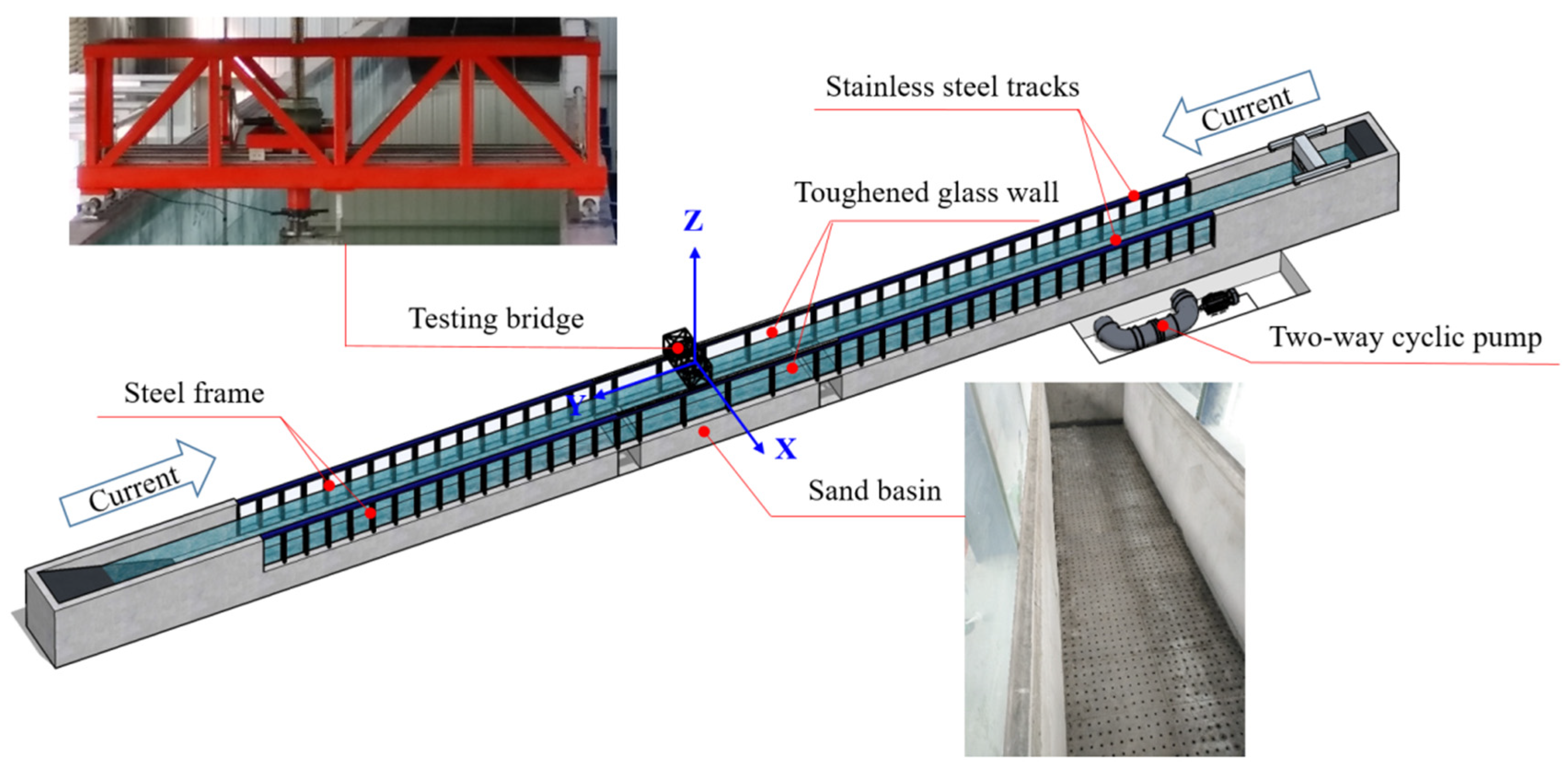
The tests were conducted in the flume at Southwest Jiaotong University; it was 60 m in length, 2 m in width, and 1.8 m in height. As shown in Figure 1, the flume was equipped with a two-way cyclic pump, which could generate steady current in both positive and negative directions in the Y direction. The laboratory flume had a flat concrete bottom. The longitudinal slope of the flume bottom during the steady-state flow conditions was always 0°. There was a sand basin in the middle of the flume, which was 7.5 m in length, 2 m in width, and 0.35 m in height. Tests were conducted in the downstream part of the sand basin. Upstream length was designed to provide a sand supply to the test section to avoid excessive loss of sand in the test area. The surface of the sand was carefully leveled and flattened before the test to ensure that the initial sediment surface was the same for all working conditions.
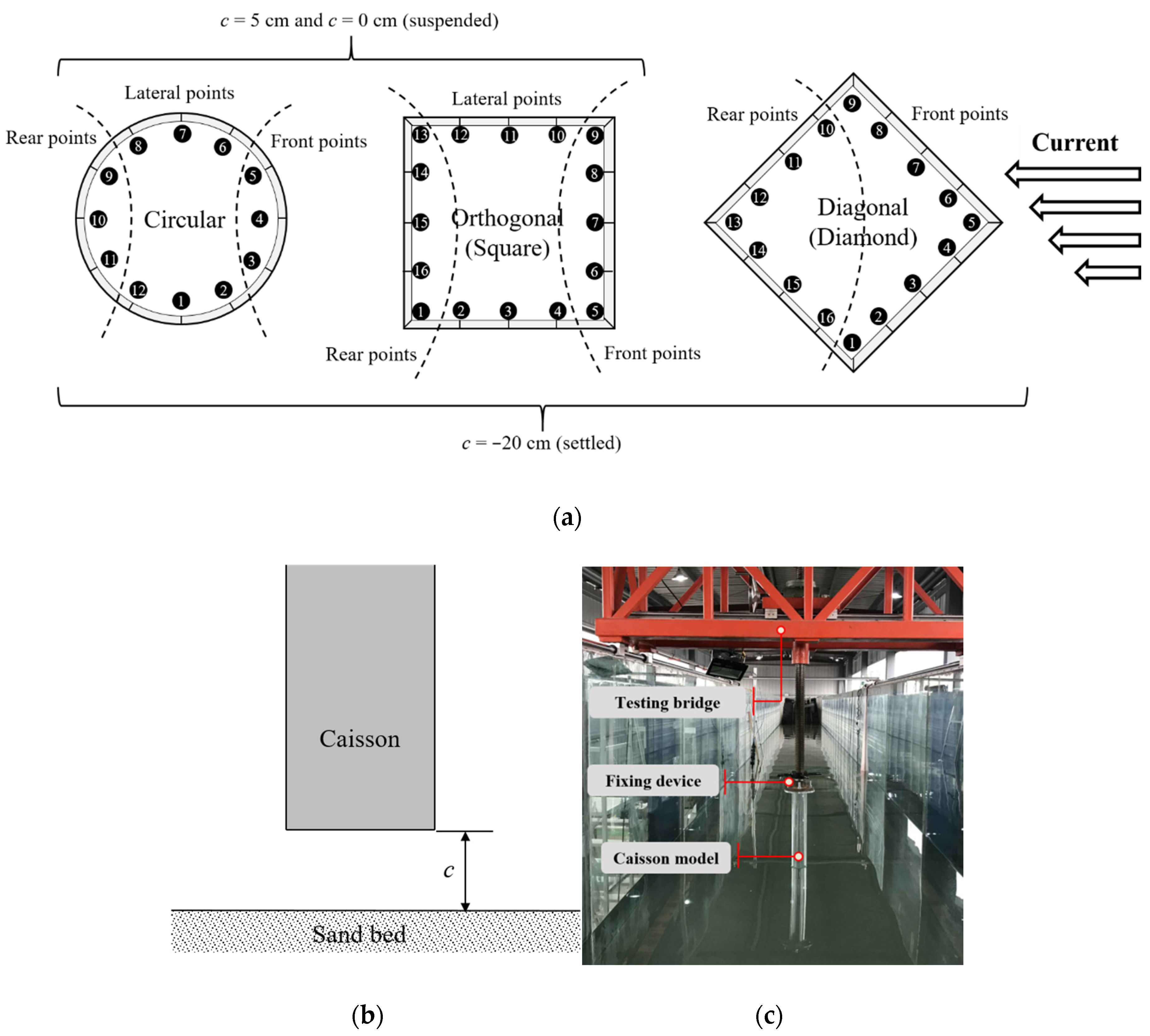
Two cross-sections (circular and square) of caisson models were chosen for the experiments, as shown in Figure 2a. The diameter of the circular caisson and the dimensions of the square caissons were both 0.15 m. Figure 2b shows the side view of the caisson suspended in water. In this study, c refers to the clearance between the caisson bottom and the sand bed, which was set to 5 cm and 0 cm. A value of c equal to −20 cm represents the caisson settled into the sediment. The circular and square caissons (orthogonal and diagonal) were used to study the local scour around caissons settled into the sediment (c = −20 cm). When the caisson was suspended in water, the circular and square caissons (orthogonal) were used to study the difference in local scour between unidirectional current and tidal current. In order to distinguish the caissons more clearly, in this paper, the square caisson orthogonal to the direction of the current is referred to as the square caisson, and the square caisson diagonal to the direction of the current is referred to as the diamond caisson. Twelve measuring points (circular) and 16 measuring points (square/diamond) were evenly arranged around the caisson at the same distance to monitor the scour depth around the caissons. These measuring points along the boundary of the caissons were divided into front points, rear points, or lateral points to investigate the development of local scour, as shown in Figure 2a.
In the experiment, a GoPro camera was used for data acquisition of scour depth around the caisson models in the water. The installation of the caisson model in the flume is shown in Figure 2c. The top of the caisson model was fixed to the testing bridge using bolts to ensure structural rigidity in the scour-testing process. Current velocity was measured via acoustic Doppler velocimetry (ADV), and velocity distribution along the water depth was measured by moving the ADV up and down.
2.2. Calculation of Test Parameters
Natural river sand with a median particle size d50 of 0.316 mm and a sediment specific gravity of 2.69 was used as the bed sediment in this study. The water depth h was set to 0.4 m. The non-dimensional particle size is defined as , in which the kinematic viscosity . The critical Shields parameter of the sediment can be calculated according to the method proposed by Soulsby and Whitehouse [33] as follows, and is equal to 0.0363:
The Shields parameter due to skin friction is defined as follows:
where is the water density, g is the acceleration due to gravity, and is the shear stress due to bottom friction, which is fundamental to check whether the prepared experiments are in clear water or live bed conditions. Two methods are used to estimate the value of , respectively.
Since the sand surface is flat, the bed shear stress is first calculated according to the method proposed by Soulsby [34], which relates the average shear stress at the bed to the square of the average fluid velocity (), as follows:
where is the logarithmic relationship, equal to 2.15 × 10⁻³ by calculation; is the Karman constant, is the roughness height and is the depth-average flow velocity. In the following tests, the constant flow velocity close to the water surface is set to 0.35 m/s with a depth-averaged value of 0.322 m/s. The shear stress according to Equation (3) equals to 0.2228 N/m2. The value of for the sediment is 0.0434.
It should be noted that Equation (3) expresses the average shear stress in the cross-section, which neglects the impact of the current on both the rough sandy bottom and the smooth glass walls of the flume. Therefore, the average shear stress on the sandy bottom of the flume can be calculated by another method [35,36] as:
in which is hydraulic radius for the section related to the bottom, is the energy slope of the flume and approximately equal to 1.0 × 10⁻⁴ [37]. This method assumes that the average flow velocities are equal to the depth-averaged velocity across the entire cross-section :
where and are the average velocities at the wall and sand bottom zone, respectively. Expressing the average velocity by Darcy-Weisbach formula, we have:
where is the coefficient of resistance for a whole cross-section of varying roughness, and are the wall and bottom coefficient of resistance, respectively. For a rectangular cross-section with depth and bottom width , can be calculated by:
Hydraulic radius of the whole section is defined as:
where , and is the area of velocity field connected with the wall’s and bottom’s roughness, respectively. The hydraulic radius values and in Equation (6) can then be calculated as and . After calculation, the value of for the sediment is hence equal to 0.034 N/m2. the value of for the sediment is hence equal to 0.065.
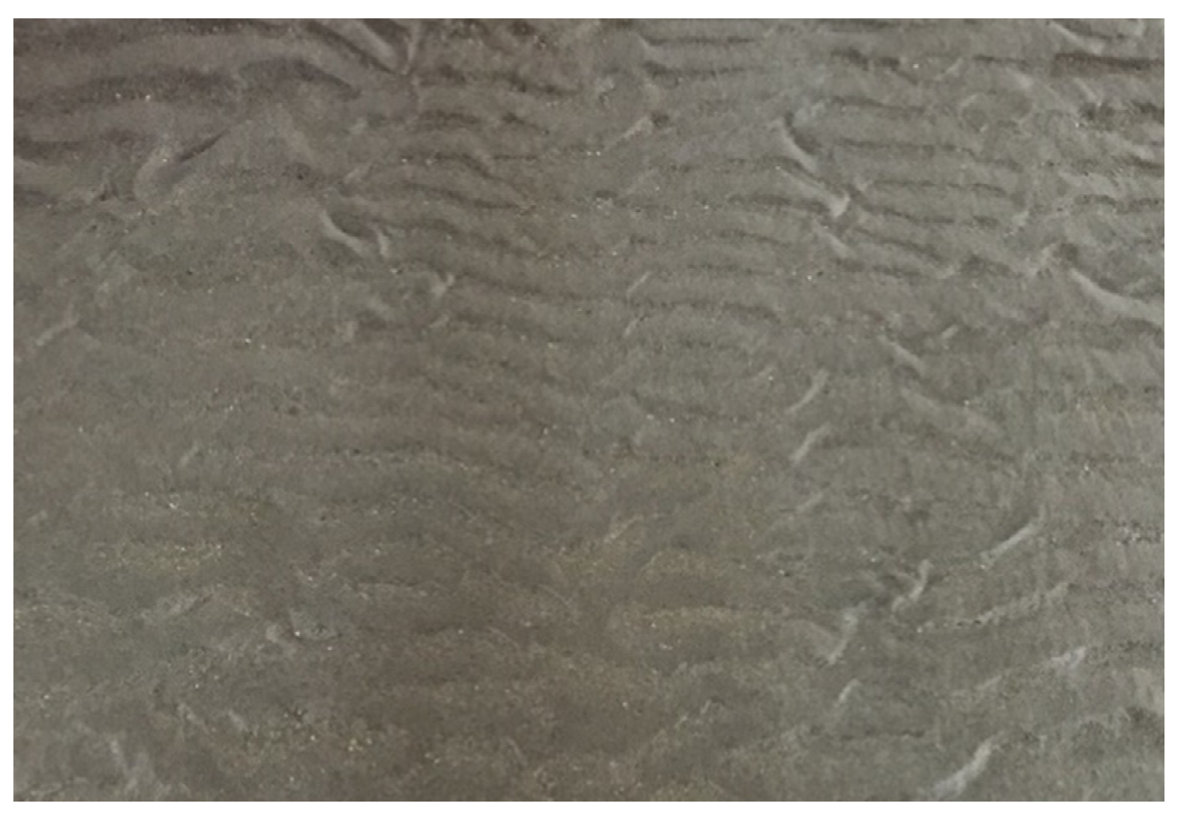
The Shields parameters from both methods of bed shear stress estimation are all larger than , which indicates that the scour is in a live-bed condition. This judgement was then confirmed by the validation scour test without specimen. Sand ripples were formed along the sediment bed as shown in Figure 3. The height of the ripples was between 0.01 and 0.02 m, which was smaller than the horizontal dimension of the model caisson. The effect of the sand ripples on the experimental results was therefore neglected due to their small size.
In order to approximately determine the duration for the scour test, the timescale of the scour based on the empirical formulas proposed by Sumer et al. [38] is calculated as follows:
where, is the scour depth, is the equilibrium scour depth, is time, and the timescale is defined as follows [27,38]:
where is the representative dimension (dimension perpendicular to flow for a square caisson), is the boundary-layer thickness, and is the dimensionless timescale.
Substituting and the calculated timescale into Equation (9), the time taken for the scour to reach 99% of the equilibrium scour depth for D = 0.15 m is t = 0.68 h. The duration of the scour tests was finally set to 3 h for unidirectional current and 1 h for tidal current, according to the calculated and test results. The test results for unidirectional current and tidal current were compared within the same time range.
2.3. Testing Currents and Cases
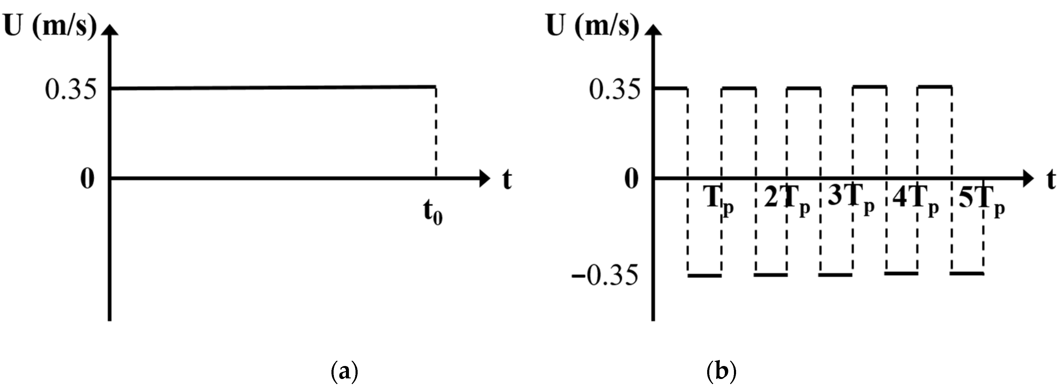
In the tests, two types of current (unidirectional current and tidal current) were used to study the local scour around caissons. The unidirectional current always flowed along the positive direction of the Y axis in the flume and remained at a constant velocity of 0.35 m/s. The velocity of the tidal current also remained constant at 0.35 m/s, but its direction of flow changed every 5 min along the positive and negative directions of the Y axis. The period (Tp) of tidal current was 10 min, which was also adopted by Vasquez and Walsh [39]. The velocity and direction versus time for unidirectional current and tidal current in the experiments are shown in Figure 4. The quantities t0 and Tp represent the duration of unidirectional current and period of tidal current, respectively.
3. Results
There are 14 testing cases conducted in this study. All of the test cases and parameters are given in Table 1. Cases 1–6 are settled caisson specimen, and the rest cases are suspended caisson specimen with two clearances. Each setup of caisson specimen has two scour tests, including unidirectional and tidal current. The settled cases adopt three type of cross-sections, while the suspended cases only consider circular and square. For general and scientific illustration, the scour depth of caisson is scaled by the diameter for the circular specimen and the projected width of the specimen for the square or diamond specimen as a non-dimensional parameter. According to Equation (10), the non-dimensional time of the scour testing time can be calculated by:
3.1. Local Scour around Caissons Settled into the Sediment
3.1.1. Circular Caisson
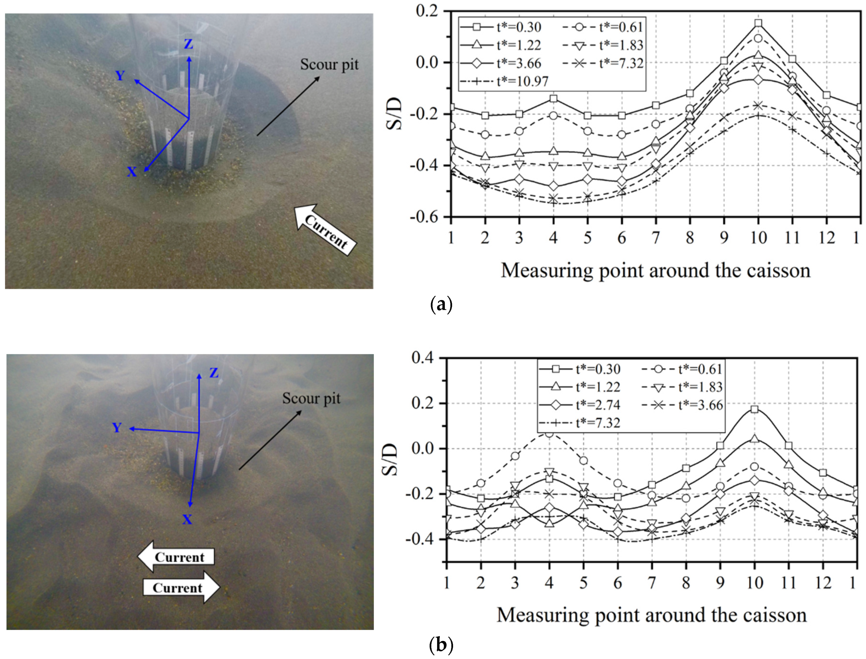
Figure 5 shows photographs of the scour pit and the time development of scour depth around the circular caisson under unidirectional and tidal current. As shown in Figure 5a, the time development of the scour depth around the circular caisson increased regularly and gradually under unidirectional current. The maximum scour depth occurred at the middle of the front points (No. 4 point). The influence of factors such as current-generating errors, reflection of the side wall water flow, sediment properties, measurement errors, and deviation of the caisson placement during the test resulted in certain errors, which made the data for the measured points not strictly symmetrical. The overall data, however, were relatively symmetrical, and the deviations in the data were within the acceptable range.
It can be clearly seen from Figure 5b that the time development of the scour depth around the circular caisson changed up and down under tidal current, and the maximum scour depth appeared at the two side points (Nos. 1 and 7). The scour pit showed a strong symmetry on both the X and Y axes under tidal current. The maximum scour depth for tidal current was smaller than that for unidirectional current at t* = 7.32 (t = 120 min). This was due to the backfilling and deposition of the sediment caused by the tidal current, which led to the reduction in scour depth. The maximum scour depth at t* = 3.66 (t = 60 min) was as high as 95% of the maximum scour depth at t* = 7.32 (t = 120 min). This suggests that the development of the scour depth around the caisson was relatively slow, which also shows that it was reasonable to set the scour time at t* = 3.66 (t = 60 min) under tidal current for subsequent cases.
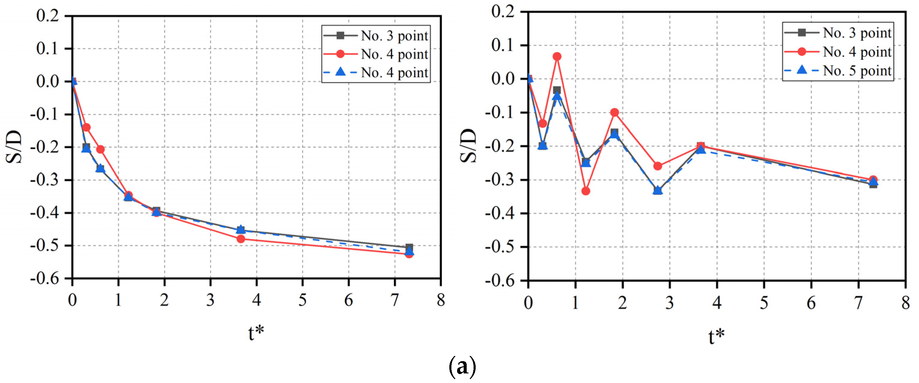
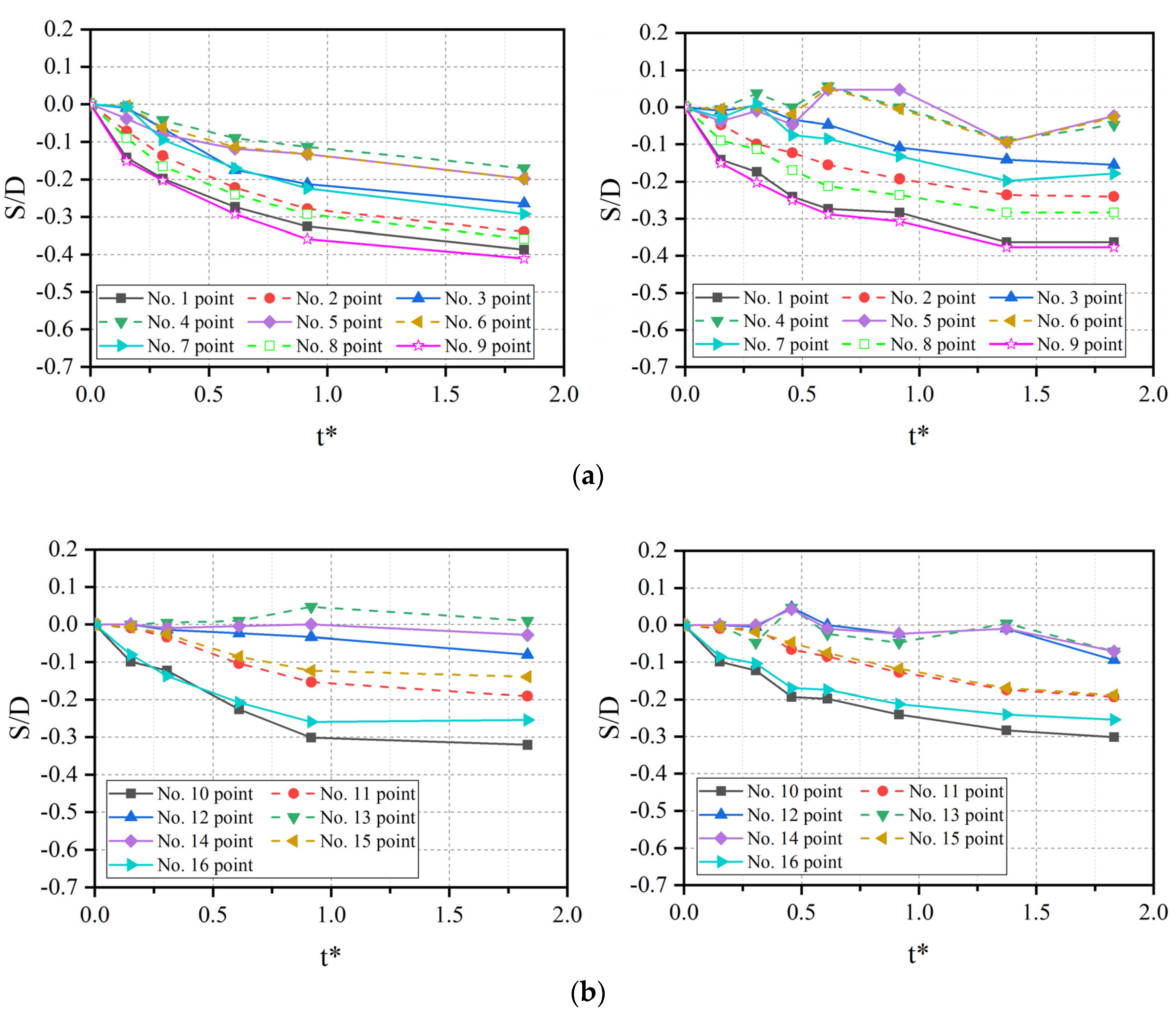
Figure 6 shows a comparison of the development of non-dimensional scour depth around the circular caisson under unidirectional current and tidal current within 120 min. It can be seen from Figure 6a that the scour depth at the front points of the circular caisson increased gradually, and the variation in the time development of scour depth was the same under unidirectional current. Due to the back and forth action of the tidal current, the scour depths of the three front points of the caisson increased with an oscillatory time period. Figure 6b shows that the scour depths at the lateral points of the circular caisson increased with time, regardless of whether the current was unidirectional or tidal. However, the increase in scour depth under tidal current also oscillated, but not intensely, as for the front and rear points, which shows that the lateral points were less affected by the change in direction of the tidal current. It can be seen from Figure 6c that the deposition of sediment occurred at all rear measuring points in the initial stage of scour and also oscillated, especially the No. 10 point, which displayed the most obvious phenomena of backfilling and deposition.
3.1.2. Square Caisson
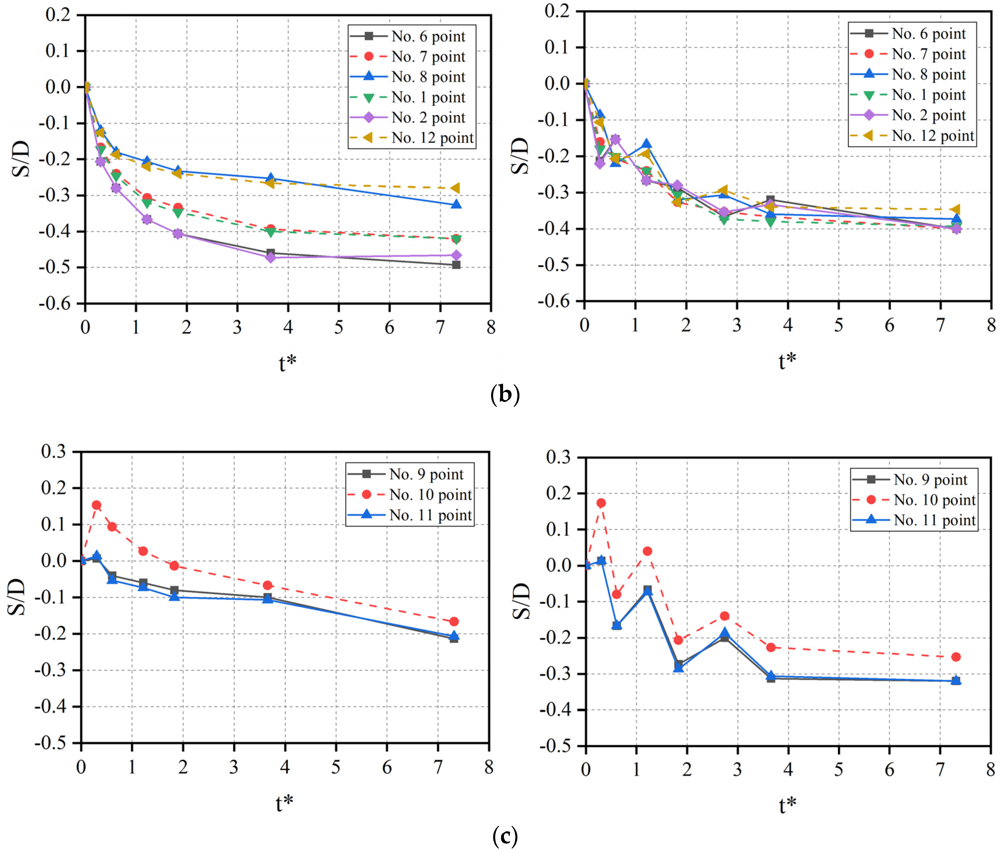
Figure 7 shows photographs of scour pits and the non-dimensional scour depth around the square caisson under unidirectional current and tidal current. As shown in Figure 7a, under the unidirectional current, the scour depth at the upstream corners (Nos. 5 and 9) occurred at the first points. Sediments washed out from the upstream corners were deposited at the two downstream corners, Nos. 1 and 13. The scour was propagated from the upstream corners toward the downstream corners and also toward the central part of the upstream boundary. In the beginning stage t* < 0.61 (t < 10 min), the scour of the caisson boundary developed slower than at the upstream corners of the caisson. After 10 min, the scour of the caisson boundary developed quickly. Then, the scour depth of the caisson boundary gradually approached the scour depth of the upstream corners. After 180 min of scour, the maximum scour depth of the caisson boundary was about 93% of the maximum scour depth of the upstream corners. The maximum scour depth at t* = 10.97 (t = 180 min) occurred at the upstream corners (Nos. 5 and 9).
It is well known that the maximum scour depth around a circular pile is due mainly to the horseshoe vortex upstream of the pile. Therefore, if the horseshoe vortex is strong enough at the upstream boundary of the square caisson, the scour will appear at the center of the upstream boundary and develop intensely in the initial stages of scour. However, the test results showed that the maximum scour depth occurred at the two upstream corners of the square caisson and that the scour depth of the upstream boundary was small in the initial stages of scour, which indicates that the horseshoe vortex is not the main factor affecting the maximum scour depth, but the acceleration of velocity at the upstream corners. This is because the acceleration of velocity increased the shear stress at the upstream corners of the square caisson and led to a deeper scour depth.
As shown in Figure 7b, the development of scour at each measuring point was oscillatory and had no pronounced regularity under tidal current, and the scour pit was symmetrical on the X and Y axes. The position of the maximum scour depth changed repeatedly at both the upstream and the downstream corners, and was smaller than that under unidirectional current.
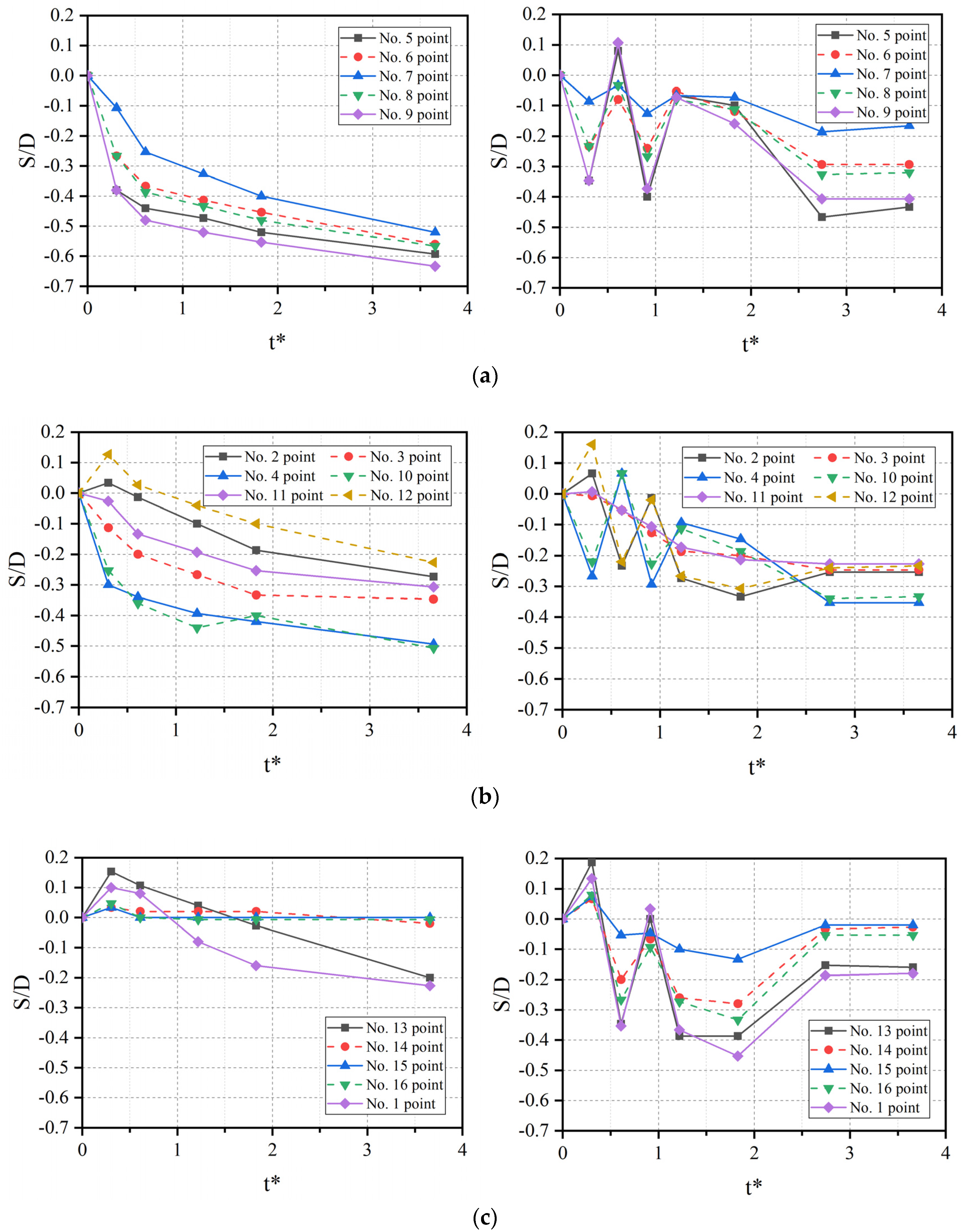
For the square caisson, as shown in Figure 8, under unidirectional current, the scour depth at the front points of the square caisson developed more rapidly than that at the lateral and rear points, especially at the two upstream corners (Nos. 5 and 9). The development of scour depth at the symmetrical measuring points on both sides of the square caisson was the same. The sediment was deposited at the rear points in the initial stages of scour, and then washed away. Under tidal current, the scour depth at the front points showed oscillatory change as a result of sediment deposition. Only at the middle points (Nos. 3 and 11) of the lateral points did the scour depth increase, which indicates that the influence of tidal current was limited here. The scour depth at almost all measuring points varied with the period and showed deposition and erosion alternately.
3.1.3. Diamond Caisson
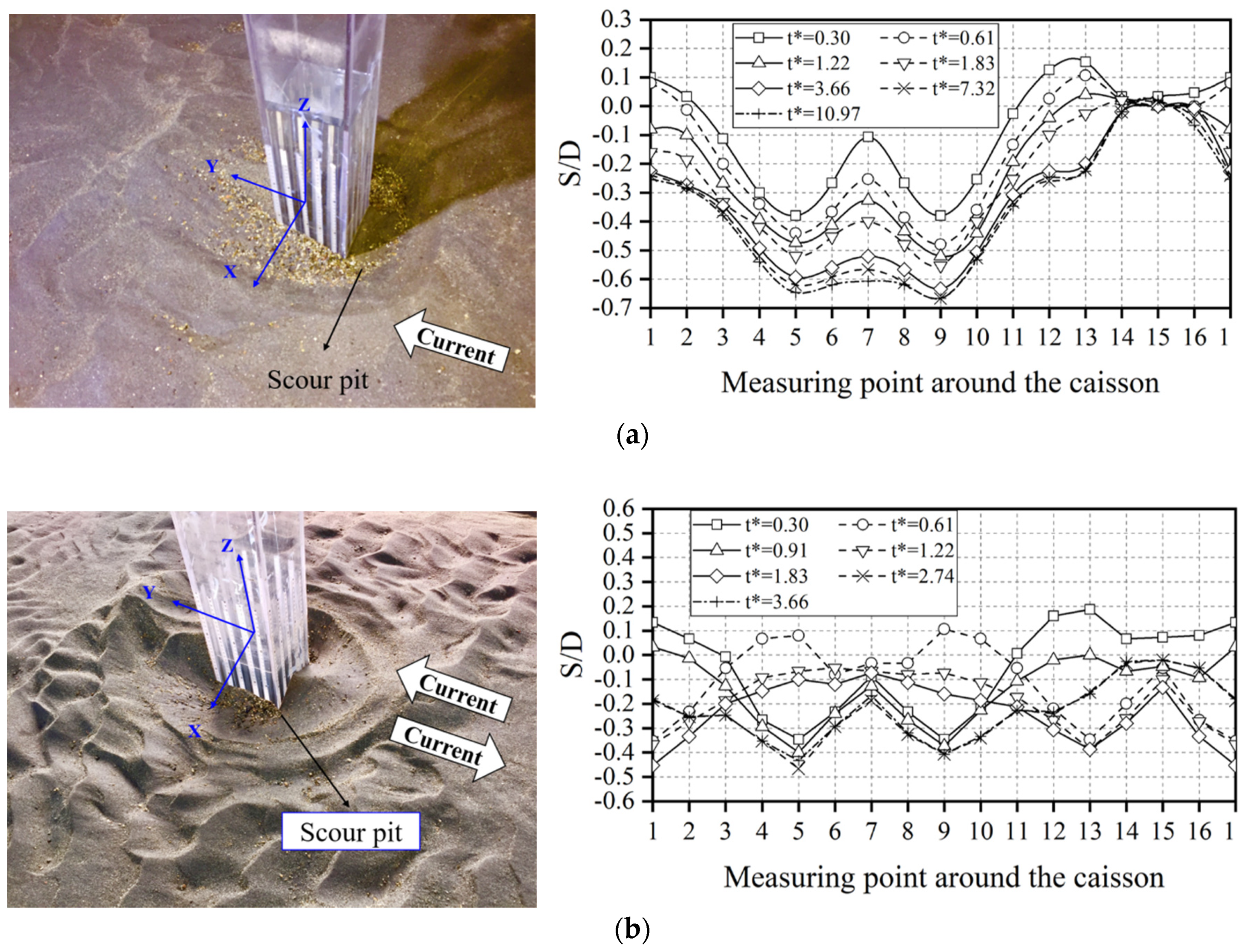
It is interesting to see in Figure 9a that the scour at the upstream corner (No. 5 point) was initiated later than that at the two side corners (Nos. 1 and 9) of the caisson and developed slowly in the initial stages of scour. This was because the sharp nose at the upstream corner, which resulted in a horseshoe vortex, was not formed effectively and separated the current to reduce the erosive ability of the current. Scour at the two side corners developed rapidly because of the acceleration of velocity. In the later stages of scour, the scour at the upstream corner (No. 5 point) began to develop rapidly because the scour pit at the side corners (Nos. 1 and 9) extended to No. 5 point, but the maximum scour depth at the upstream corner was 7 cm, which was still less than the maximum scour depth of 9 cm at the side corners. It can be seen from Figure 9b that the degree of development of the scour depth at every point was smaller than that under unidirectional current due to the change in direction under tidal current. The maximum scour depth always occurred at the side corners (Nos. 1 and 9) of the diamond caisson whether the current was unidirectional or tidal.
For the diamond caisson, as shown in Figure 10a, the scour depth at the front points of the caisson increased gradually with time under unidirectional current, while the middle three points (Nos. 4, 5, and 6) were oscillatory due to the significant change in current direction under tidal current. It can be seen from Figure 10b that, under the action of unidirectional current, the development of scour depth at the rear points was the same as that at the front points, except for the middle three points (Nos. 12, 13, and 14) behind the caisson, where the deposition of sediment occurred in the initial stages of scour. Under the action of tidal current, the middle three points of the rear points were significantly affected by the change in tidal current direction, which changed repeatedly between deposition and scouring; thus, the maximum scour depth at these three points was limited.
3.1.4. Analysis and Comparison of the Maximum Scour Depths
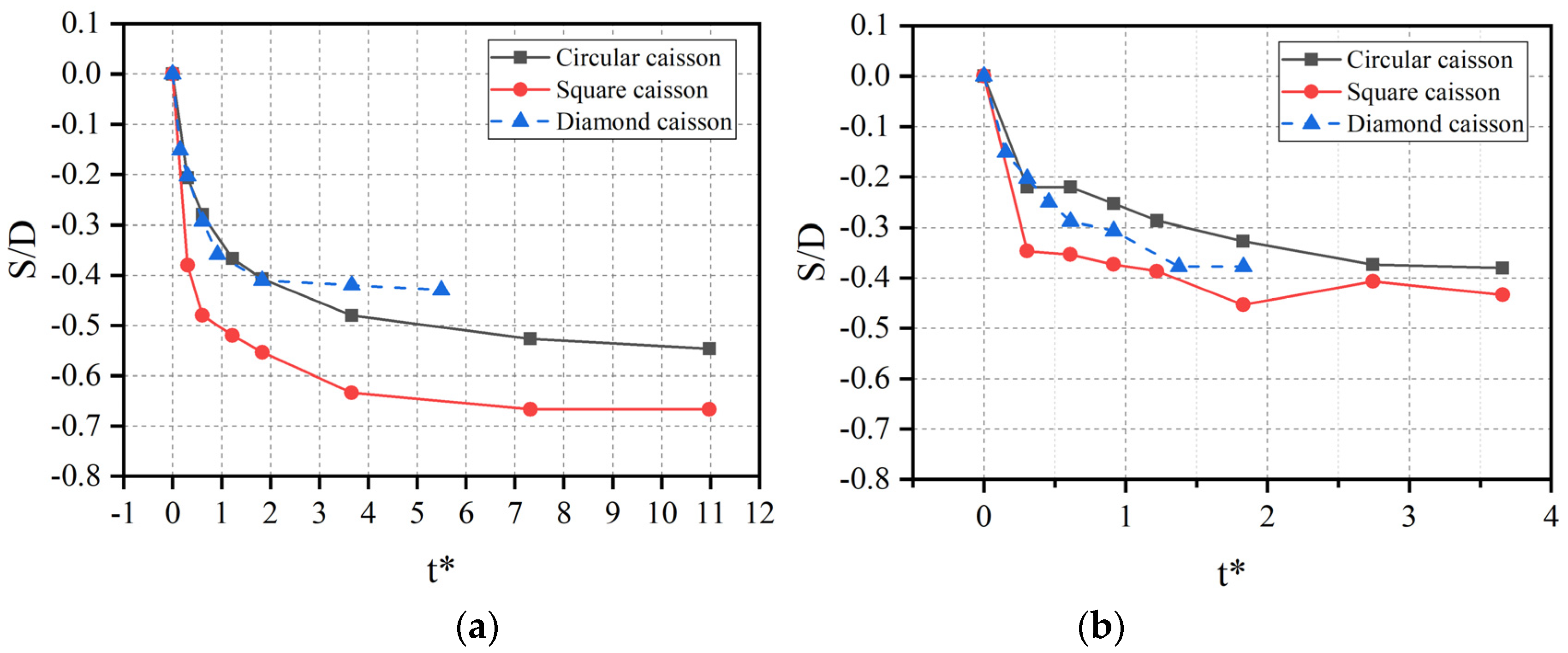
Figure 11a shows a comparison of the maximum scour depth around the caissons with different cross-sections under unidirectional current. It is clear that the maximum scour depth around the diamond caisson was the smallest, while the maximum scour depth around the square caisson was the largest among the three caissons. Due to the different representative dimension D (dimension perpendicular to flow for a caisson), the non-dimensional time of diamond caisson was smaller than that of the circular and square caissons at the same time. However, it can still be seen from Figure 11a that diamond has the slowest temporal developing speed of scour and can reach quasi-equilibrium state easier, while square has the fastest speed. At t = 180 min t* = 10.97 for circular and square, t* = 5.49 for diamond, the maximum scour depths of the diamond caisson and the square caisson were 22% larger and 21.5% smaller, respectively, than that of the circular caisson. Compared with the square caisson, the circular caisson was more similar to an active scour countermeasure because a circular water-facing surface can divert the current, change its direction, and decrease the strength of the current; thus, the scouring ability is weakened [40]. The diamond caisson also had two 45° sides on the water-facing surface, which could play a certain energy-dissipating role. The two side corners could result in the acceleration of velocity, but generation of the horseshoe vortex was not easy here, which can result in a smaller scour depth than the circular caisson. However, the square caisson did not show diversion on the water-facing surface, which led to a vortex with a strong scouring ability; thus, the maximum scour depth was the largest of the three caissons.
It can be seen from Figure 11b that the development of the maximum scour depth under tidal current was slower and reached a stable value more easily than under unidirectional current. In the initial stage of scour, the development of diamond caisson was faster than that of the circular caisson, but with the development of scour, it was easier for the diamond caisson to reach a quasi-equilibrium state. It is interesting to note that the maximum dimensionless scour depth (S/D) of the diamond caisson was almost the same as that of the diamond caisson at t = 60 min (t* = 3.66 for circular and square, t* = 1.83 for diamond). This was because the two corner points on the water-facing surface of the square caisson became the points on the water-back surface where the direction of the tidal current changed, which affected the development and growth of the scour depth. However, the maximum scour depth around the diamond caisson and circular caisson appeared at the two side points; the change in tidal current direction did not affect the continuous scour of the side points. Therefore, if the representative dimensions D of the circular and diamond caissons are the same under the action of tidal current, the maximum scour depth of both will be close to each other.
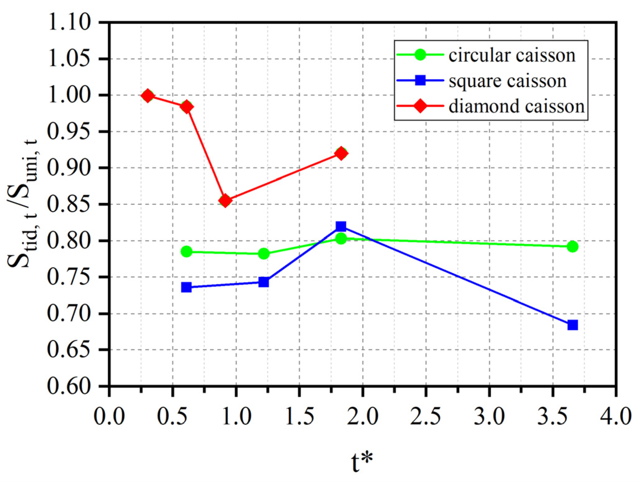
Figure 12 shows values of the scour depth ratio Stid,t/Suni,t for different cross-sections of caissons as a function of non-dimensional time t*. Stid,t represents the maximum scour depth under the action of tidal current at time t* and Suni,t represents the maximum scour depth under the action of unidirectional current at time t*. The scour depth ratio Stid,t/Suni,t can reflect the degree to which the scour depth of caissons with different cross-sections is affected by tidal current. The larger the Stid,t/Suni,t ratio is, the less sensitive the caisson with this cross-section is to tidal current. Compared with the scour under unidirectional current, the square caisson was more sensitive, while the diamond caisson was less sensitive to the tidal current.
3.2. Local Scour under Caissons Suspended in Water
In order to investigate the difference in scour under unidirectional current and tidal current when the caisson was suspended in water, caissons with two different cross-sections (circular and square) commonly used as bridge foundations were chosen for this experiment and placed at c = 5 cm, c = 0 cm, and c = −20 cm (settled).
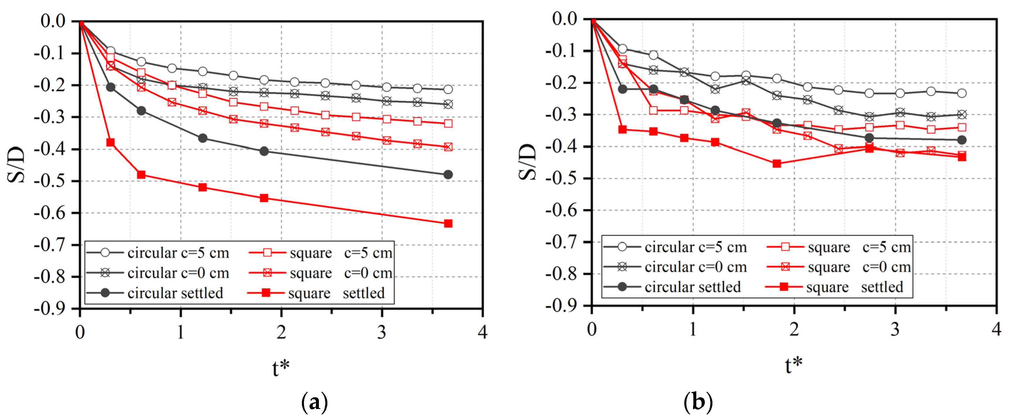
Figure 13 shows the development of the maximum scour depth with time when the caisson was suspended in water or settled into the sediment. When the caisson was suspended in water (c = 5 and 0 cm), the maximum scour depth of tidal current was larger than that of unidirectional current no matter what the cross-section of the caisson. This shows that, under tidal current, when the caisson was suspended in water, the sediment under the caisson was easily washed away without the shelter of the caisson. The change in direction of tidal current results in the backfilling and deposition of sediment, most of which consisted of fine particles that were easily washed away. It can also be seen from the results of these experiments that when the fine particles were backfilled and deposited in the scour pit, they were immediately washed away, and the coarse particles were left in the scour pit. The coarse particles rolled, jumped, and slid in the scour pit with the change in direction of the tidal current, which caused the fine particles underneath the coarse particles to be exposed and transported by the water flow. However, the coarse particles in the scour pit were relatively stable under unidirectional current. Therefore, the maximum scour depth of tidal current was larger than that of unidirectional current when the caisson was suspended in water. When the caisson was settled into the sediment, the maximum scour depth of tidal current was smaller than that of unidirectional current due to the shielding effect of the caisson. The maximum scour depth and the development of the circular or square caisson both increased with the caisson gradually sinking into the sediment. Under unidirectional current, when the caisson was close to the sediment surface (c = 0 cm), the maximum scour depth of the circular caisson and the square caisson reached 54.2% and 62.1% of the value for the settled caisson, respectively. Under tidal current, the maximum scour depth of the circular caisson and the square caisson (c = 0 cm) reached 78.9% and 98.5% of the value for the settled caisson, respectively. This shows that the scour depth cannot be ignored when the caisson is suspended in water during the caisson construction stage.
4. Conclusions
This study conducted experiments of the local scour around caissons with different cross-sections and clearance under both unidirectional and tidal currents. The scour depth along the boundaries of settled caisson specimens with three different cross-sections (circular, square, and diamond) was measured by means of a series of flume tests. Suspended caisson specimens with two cross-sections (circular and square) were then used to investigate the scour when the caisson was suspended in the water. The main findings are summarized below.
(1) The effect of current type influences the local scour around the caisson settled into the sediment. The development of the scour depth under tidal current was slower than that under unidirectional current, although the scour depth is also gradually increased. The maximum scour depth of tidal current was smaller than that of unidirectional current. The locations of the maximum scour depth of circular and square caisson under tidal current are different from that under unidirectional current, while they are located at the same points for the diamond caisson under both unidirectional and tidal current.
(2) The appropriate shape of the water-facing surface on the caisson had the function of active scour countermeasure, which could decrease the strength of the flow transport energy to reduce the scour depth. The diamond caisson had the smallest maximum scour depth under both currents. The maximum scour depth of tidal current was about 78–80% (circular), 68–82% (square), and 85–100% (diamond) of the maximum scour depth of unidirectional current, which indicates that the local scour of the square caisson was the most sensitive to the effect of tidal current, the diamond caisson being the least sensitive.
(3) The acceleration of velocity in the clearance between the caisson bottom and the sediment was the main cause of scour for the caisson suspended in the water. The maximum scour depth increased with the caisson sinking down gradually. The maximum scour depth of the suspended caisson was only 54.2–98.5% of that of the settled caisson. When the caisson was suspended in the water, the maximum scour depth of tidal current was larger than that of unidirectional current due to the change in tidal current direction, which is different from that of the settled caisson.
It should be noted that the above conclusions were drawn based on experiments with only one constant current velocity, live bed condition, three cross-sections, and one type of sediment. A more general understanding of this question requires more experiments or numerical simulations. Notwithstanding these shortcomings, this research provides a useful experimental reference for academic research and engineering assessment of local scour around caissons under unidirectional and tidal currents.
Author Contributions
Conceptualization, Q.X., K.W. and Y.L.; Data curation, Q.X.; Formal analysis, Q.X., F.Q. and C.Y.; Investigation, Q.X. and F.Q.; Supervision, K.W. and Y.L.; Writing—original draft, Q.X., K.W. and C.Y.; Writing—review & editing, Q.X., K.W., C.Y. and Y.L. All authors have read and agreed to the published version of the manuscript.
Funding
This research was funded by the National Natural Science Foundation of China (Grant Nos. 51478400, 51708455, and 51978578).
Acknowledgments
The authors sincerely thank the anonymous reviewers for their valuable suggestions in improving the manuscript.
Conflicts of Interest
The authors declare no conflict of interest.
References
- Ti, Z.; Zhang, M.; Li, Y.; Wei, K. Numerical study on the stochastic response of a long-span sea-crossing bridge subjected to extreme nonlinear wave loads. Eng. Struct. 2019, 196, 109287. [Google Scholar] [CrossRef]
- Zhang, M.; Yu, J.; Zhang, J.; Wu, L.; Li, Y. Study on the wind-field characteristics over a bridge site due to the shielding effects of mountains in a deep gorge via numerical simulation. Adv. Struct. Eng. 2019, 22, 3055–3065. [Google Scholar]
- Wei, K.; Liu, Q.; Qin, S. Nonlinear assessment of offshore steel trestle subjected to wave and current loads. Ships Offshore Struct. 2019, 1–13. [Google Scholar] [CrossRef]
- Liang, F.; Wang, C.; Yu, X. Performance of Existing Methods for Estimation and Mitigation of Local Scour around Bridges: Case Studies. J. Perform. Constr. Facil. 2019, 33, 04019060. [Google Scholar] [CrossRef]
- Melville, B.W. Local Scour at Bridge Sites; The University of Auckland: Auckland, New Zealand, 1975. [Google Scholar]
- Blanco, G.; Ye, A.; Wang, X.; Goicolea, J.M. Parametric Pushover Analysis on Elevated RC Pile-Cap Foundations for Bridges in Cohesionless Soils. J. Bridge Eng. 2019, 24, 04018104. [Google Scholar] [CrossRef]
- Wang, X.; Ye, A.; Shang, Y.; Zhou, L. Shake-table investigation of scoured RC pile-group-supported bridges in liquefiable and nonliquefiable soils. Earthq. Eng. Struct. Dyn. 2019, 48, 1217–1237. [Google Scholar] [CrossRef]
- Zhang, J.; Wei, K.; Qin, S. An efficient numerical model for hydrodynamic added mass of immersed column with arbitrary cross—Section. Ocean Eng. 2019, 187, 106192. [Google Scholar] [CrossRef]
- Sumer, B.M.; Fredsøe, J. The Mechanics of Scour in the Marine Environment; World Scientific: Singapore, 2002. [Google Scholar]
- Melville, B.W.; Coleman, S.E. Bridge Scour; Water Resources Publications: Highlands Ranch, CO, USA, 2000. [Google Scholar]
- Arneson, L.A.; Zevenbergen, L.W.; Lagasse, P.F.; Clopper, P.E. Evaluating Scour at Bridges, 5th ed.; Hydraulic Engineering Circular No. 18 (HEC-18); Federal Highway Administration: Washington, DC, USA, 2012. [Google Scholar]
- Ataie-Ashtiani, B.; Beheshti, A.A. Experimental Investigation of Clear-Water Local Scour at Pile Groups. J. Hydraul. Eng. 2006, 132, 1100–1104. [Google Scholar] [CrossRef] [Green Version]
- Oliveto, G.; Hager, W.H. Temporal Evolution of Clear-Water Pier and Abutment Scour. J. Hydraul. Eng. 2002, 128, 811–820. [Google Scholar] [CrossRef]
- Penna, N.; Coscarella, F.; Gaudio, R. Turbulent Flow Field around Horizontal Cylinders with Scour Hole. Water 2020, 12, 143. [Google Scholar] [CrossRef] [Green Version]
- Oliveto, G.; Comuniello, V.; Bulbule, T. Time-dependent local scour downstream of positive-step stilling basins. J. Hydraul. Res. 2011, 49, 105–112. [Google Scholar] [CrossRef]
- Breusers, H.N.C.; Nicollet, G.; Shen, H.W. Local scour around cylindrical piers. J. Hydraul. Res. 1977, 15, 211–252. [Google Scholar] [CrossRef]
- Wang, S.; Wei, K.; Shen, Z.; Xiang, Q. Experimental Investigation of Local Scour Protection for Cylindrical Bridge Piers Using Anti-Scour Collars. Water 2019, 11, 1515. [Google Scholar] [CrossRef] [Green Version]
- Schendel, A.; Welzel, M.; Hildebrandt, A.; Schlurmann, T.; Hsu, T.-W. Role and Impact of Hydrograph Shape on Tidal Current-Induced Scour in Physical-Modelling Environments. Water 2019, 11, 2636. [Google Scholar] [CrossRef] [Green Version]
- McGovern, D.J.; Ilic, S.; Folkard, A.M.; McLelland, S.J.; Murphy, B.J. Time Development of Scour around a Cylinder in Simulated Tidal Currents. J. Hydraul. Eng. 2014, 140, 04014014. [Google Scholar] [CrossRef]
- Wang, J. Research on Local Scour at Bridge Pier under Tidal Action. Matec Web Conf. 2015, 25, 01013. [Google Scholar] [CrossRef]
- Zhang, J.-S.; Gao, P.; Zheng, J.-H.; Wu, X.-G.; Peng, Y.-X.; Zhang, T.-T. Current-Induced Seabed Scour Around a Pile-Supported Horizontal-Axis Tidal Stream Turbine. J. Mar. Sci. Technol. 2015, 23, 929–936. [Google Scholar]
- Schendel, A.; Hildebrandt, A.; Goseberg, N.; Schlurmann, T. Processes and evolution of scour around a monopile induced by tidal currents. Coast. Eng. 2018, 139, 65–84. [Google Scholar] [CrossRef]
- Ma, L.; Wang, L.; Guo, Z.; Jiang, H.; Gao, Y. Time development of scour around pile groups in tidal currents. Ocean Eng. 2018, 163, 400–418. [Google Scholar] [CrossRef]
- Xiang, Q.; Li, Y.; Wei, K.; Wang, S.; Yao, C. Review of Bridge Foundation Scour. J. Southwest Jiaotong Univ. 2019, 54, 235–248. [Google Scholar]
- Veerappadevaru, G.; Gangadharaiah, T.; Jagadeesh, T.R. Vortex scouring process around bridge pier with a caisson. J. Hydraul. Res. 2011, 49, 378–383. [Google Scholar] [CrossRef]
- Veerappadevaru, G.; Gangadharaiah, T.; Jagadeesh, T.R. Temporal variation of vortex scour process around caisson piers. J. Hydraul. Res. 2012, 50, 200–207. [Google Scholar] [CrossRef]
- Zhao, M.; Zhu, X.; Cheng, L.; Teng, B. Experimental study of local scour around subsea caissons in steady currents. Coast. Eng. 2012, 60, 30–40. [Google Scholar] [CrossRef]
- Liang, F.; Wang, C.; Huang, M.; Li, J. Scale Effect on Local Scour Configurations around Caisson Foundation and Dynamic Evolution. China J. Highw. Transp. 2016, 29, 59–67. [Google Scholar]
- Oliveto, G.; Marino, M.C. Temporal scour evolution at non-uniform bridge piers. Proc. Inst. Civ. Eng.-Water Manag. 2017, 170, 254–261. [Google Scholar] [CrossRef]
- Burkow, M.; Griebel, M. A full three dimensional numerical simulation of the sediment transport and the scouring at a rectangular obstacle. Comput. Fluids 2016, 125, 1–10. [Google Scholar] [CrossRef]
- Gao, Z.R.; Huang, J.W.; Zhao, X.D. Research on Local Scour during Settling of Steel Caissons for Large-scale Bridges. Ocean Eng. 2006, 24, 31–35. [Google Scholar]
- Sun, M.X. Study on Local Scour Characteristics of Caisson under the Action of Wave and Flow; Southewest Jiaotong University: Chengdu, China, 2018. [Google Scholar]
- Soulsby, R.L.; Whitehouse, R.J.S. Threshold of sediment motion in coastal environments. In Pacific Coasts and Ports ’97: Proceedings of the 13th Australasian Coastal and Ocean Engineering Conference and the 6th Australasian Port and Harbour Conference, Christchurch, New Zealand, 7–11 September 1997; University of Canterbury: Christchurch, New Zealand; pp. 145–150.
- Soulsby, R.L. Dynamics of Marine Sands; Tomas Telford Ltd.: New York, NY, USA, 1998. [Google Scholar]
- Babaeyan-Koopaei, K.; Ervine, D.A.; Carling, P.A.; Cao, Z. Velocity and Turbulence Measurements for Two Overbank Flow Events in River Severn. J. Hydraul. Eng. 2002, 128, 891–900. [Google Scholar] [CrossRef]
- Marta, K.; Zbigniew, P. Bed Shear Stress Influence on Local Scour Geometry Properties in Various Flume Development Conditions. Water 2019, 11, 2346. [Google Scholar]
- Biron, P.M.; Robson, C.; Lapointe, M.F.; Gaskin, S.J. Comparing different methods of bed shear stress estimates in simple and complex flow fields. Earth Surf. Process. Landf. 2004, 29, 1403–1415. [Google Scholar] [CrossRef]
- Sumer, B.M.; Christiansen, N.; Fredsøe, J. Time scale of scour around a vertical pile. In Proceedings of the 2nd International Offshore and Polar Engineering Conference, San Francisco, CA, USA, 14–19 June 1992; Volume 3, pp. 308–315. [Google Scholar]
- Vasquez, J.A.; Walsh, B.W. CFD Simulation of Local Scour in Complex Piers under Tidal Flow. In Proceedings of the 33th IAHR Congress: Water Engineering for a Sustainable Environment, Vancouver, BC, Canada, 9–14 August 2009; Volume 604, pp. 913–920. [Google Scholar]
- Wang, C.; Yu, X.; Liang, F. A review of bridge scour: Mechanism, estimation, monitoring and countermeasures. Nat. Hazards 2017, 87, 1881–1906. [Google Scholar] [CrossRef]
Figure 1.
3D sketch and photographs of the test flume.

Figure 2.
Description of the caisson model: (a) top view; (b) side view of the caisson suspended in the water; (c) installation of the caisson model.
Figure 2.
Description of the caisson model: (a) top view; (b) side view of the caisson suspended in the water; (c) installation of the caisson model.

Figure 3.
Photo of sand ripples in the tests.

Figure 4.
Velocity and direction versus time in the tests: (a) unidirectional current; (b) tidal current.
Figure 4.
Velocity and direction versus time in the tests: (a) unidirectional current; (b) tidal current.

Figure 5.
Photographs of the scour pit (left) and development of scour depth (right) around the circular caisson: (a) unidirectional current; (b) tidal current.
Figure 5.
Photographs of the scour pit (left) and development of scour depth (right) around the circular caisson: (a) unidirectional current; (b) tidal current.

Figure 6.
Comparison of the development of scour depth around the circular caisson at different measuring points (left: unidirectional current; right: tidal current): (a) front points; (b) lateral points; (c) rear points.
Figure 6.
Comparison of the development of scour depth around the circular caisson at different measuring points (left: unidirectional current; right: tidal current): (a) front points; (b) lateral points; (c) rear points.


Figure 7.
Photographs of the scour pit (left) and development of scour depth (right) around the square caisson: (a) unidirectional current; (b) tidal current.
Figure 7.
Photographs of the scour pit (left) and development of scour depth (right) around the square caisson: (a) unidirectional current; (b) tidal current.

Figure 8.
Comparison of the development of scour depth around the square caisson at different measuring points (left: unidirectional current; right: tidal current): (a) front points; (b) lateral points; (c) rear points.
Figure 8.
Comparison of the development of scour depth around the square caisson at different measuring points (left: unidirectional current; right: tidal current): (a) front points; (b) lateral points; (c) rear points.

Figure 9.
Photographs of the scour pit (left) and the development of scour depth (right) around the square caisson: (a) unidirectional current; (b) tidal current.
Figure 9.
Photographs of the scour pit (left) and the development of scour depth (right) around the square caisson: (a) unidirectional current; (b) tidal current.

Figure 10.
Comparison of the development of scour depth around the diamond caisson at different measuring points (left: unidirectional current; right: tidal current): (a) front points; (b) rear points.
Figure 10.
Comparison of the development of scour depth around the diamond caisson at different measuring points (left: unidirectional current; right: tidal current): (a) front points; (b) rear points.

Figure 11.
Comparison of the maximum scour depth for caissons with different cross-sections: (a) unidirectional current; (b) tidal current.
Figure 11.
Comparison of the maximum scour depth for caissons with different cross-sections: (a) unidirectional current; (b) tidal current.

Figure 12.
Scour depth ratio Stid,t /Suni,t for different caisson cross-sections.

Figure 13.
Development of the maximum scour depth over time when the caisson is suspended in water or settled into the sand: (a) unidirectional current; (b) tidal current.
Figure 13.
Development of the maximum scour depth over time when the caisson is suspended in water or settled into the sand: (a) unidirectional current; (b) tidal current.


Table 1.
List of test parameters.
| Case | Shape of Caissons | Horizontal Dimension in the Cross-Flow Direction D (m) | Type of Current | Clearance c (cm) | Velocity (m/s) | Water Depth (m) |
| 1 | Circular | 0.15 | Unidirectional | −20 | 0.35 | 0.4 |
| 2 | Square | 0.15 | ||||
| 3 | Diamond | 0.212 | ||||
| 4 | Circular | 0.15 | Tidal | |||
| 5 | Square | 0.15 | ||||
| 6 | Diamond | 0.212 | ||||
| 7 | Circular | 0.15 | Unidirectional | 5 | ||
| 8 | 0 | |||||
| 9 | Tidal | 5 | ||||
| 10 | 0 | |||||
| 11 | Square | Unidirectional | 5 | |||
| 12 | 0 | |||||
| 13 | Tidal | 5 | ||||
| 14 | 0 |
© 2020 by the authors. Licensee MDPI, Basel, Switzerland. This article is an open access article distributed under the terms and conditions of the Creative Commons Attribution (CC BY) license (http://creativecommons.org/licenses/by/4.0/).
Share and Cite
MDPI and ACS Style
Xiang, Q.; Wei, K.; Qiu, F.; Yao, C.; Li, Y. Experimental Study of Local Scour around Caissons under Unidirectional and Tidal Currents. Water 2020, 12, 640. https://doi.org/10.3390/w12030640
AMA Style
Xiang Q, Wei K, Qiu F, Yao C, Li Y. Experimental Study of Local Scour around Caissons under Unidirectional and Tidal Currents. Water. 2020; 12(3):640. https://doi.org/10.3390/w12030640
Chicago/Turabian StyleXiang, Qiqi, Kai Wei, Fang Qiu, Changrong Yao, and Yadong Li. 2020. "Experimental Study of Local Scour around Caissons under Unidirectional and Tidal Currents" Water 12, no. 3: 640. https://doi.org/10.3390/w12030640
Note that from the first issue of 2016, this journal uses article numbers instead of page numbers. See further details here.