Explicit Solution for Critical Depth in Closed Conduits Flowing Partly Full

1
Key Laboratory of Agricultural Soil and Water Engineering of Ministry of Education in Arid Areas, Northwest A&F University, Weihui Road, Yangling 712100, China
2
State Key Laboratory of Soil Erosion and Dryland Farming on the Loess Plateau, Northwest A&F University, Yangling 712100, China
*
Author to whom correspondence should be addressed.
Water 2019, 11(10), 2124; https://doi.org/10.3390/w11102124
Submission received: 7 August 2019
/
Revised: 20 September 2019
/
Accepted: 30 September 2019
/
Published: 13 October 2019
(This article belongs to the Special Issue Techniques and Applications in Water Science and Engineering: Selected Papers from the Inaugural International Symposium on Water Modelling (iSymWater2019))
Abstract
:Critical depth is an essential parameter for the design, operation, and maintenance of conduits. Circular, arched, and egg-shaped sections are often used in non-pressure conduits in hydraulic engineering, irrigation, and sewerage works. However, equations governing the critical depth in various sections are complicated implicit transcendental equations. The function model is established for the geometric features of multiple sections using the mathematical transform method and while considering non-dimensional parameters. Then, revised PSO algorithms are implemented in MATLAB, and the right solution’s formula for the critical depths in various non-pressure conduit sections is established through optimization. The error analysis results show that the established formula has broad applicability. The maximum relative errors of the formula for critical depths are less than 0.182%, 0.0629%, and 0.170% in circular, arched, and egg-shaped sections, respectively, which are more accurate than those of existing formulas; the form of the formula proposed in this work is also more compact than that of the existing formulas. The results of this research may be useful in design, operation, and maintenance in conduit engineering.
1. Introduction
Circular, arched, and egg-shaped sections are often used in non-pressure conduits in hydraulic engineering, agricultural irrigation, and sewerage works. Because conduits with circular and arched cross-sections have excellent hydraulic properties and convenient construction, circular and arched sections are widely used for free-surface water diversion conduits in hydraulic engineering and agricultural irrigation [1]. Because conduits with egg-shaped sections have functional discharge capacity and compression capability, they are often used in sewerage works in municipal engineering. Conduits carrying sediment and locations where the rock is sheet joint, weak, and very carefully laminated are usually constructed in the form of egg-shaped channels [2].
Critical depths play a significant role in the analysis, design, operation, and maintenance of conduits. Particularly in the varied flow computations, one is required to determine critical depths. Articles related to the definition and computational methods of critical depths for various sections of conduits are extensively available in previous research [3,4,5,6,7].
For conduits with circular sections, the governing equations for critical depth are implicit, and no analytical solutions exist. The critical depth is presently obtained by trial procedures and numerical and graphical methods [8,9]. Vatankhah et al. [10] established an exponential function approximate formula based on regression equations, thus increasing their accuracy but also their complexity. Vatankhah et al. [11] obtained a direct solution, but the obtained formula was too complicated to solve.
For conduits with arched sections, Liu and Wang [12] developed explicit equations for the normal and critical depths for different portions of the arched sections based on the principle of continuous optimization fitting. The obtained equation exhibited suitable accuracy, with a maximum relative error of less than 1%. However, from a hydraulic engineering viewpoint, it would be preferable to have an explicit equation with high accuracy and simple form (single equation) for directly computing the critical depths over the entire practical range of flow depth. Wang et al. [1] and Zhao et al. [13], using the curve fitting technique, developed explicit equations with low accuracy for the critical depth of an arched cross-section with maximum relative errors of approximately 5.1% and 6.4%, respectively. Liu et al. [14] developed an explicit critical depth equation just for the upper portion, so the scope of its applicability is narrow.
For conduits with egg-shaped sections, the geometry of the egg-shaped cross-section is very complicated. The egg-shaped cross-section consists of four arc segments. Specific solutions are available for critical depth [2,9]. Raikar et al. [2] used the mathematical model of regression analysis to calculate the normal and critical water depths of an egg-shaped section. Based on power function regression model fitting, Bijankhan and Kouchakzadeh [15] obtained a complicated formula for the normal and critical water depths of an egg-shaped section. The Indian standard code of practice for the design of conduits conveying water [16] provides a formula for a typical egg-shaped section; however, it still requires a more accurate formula for calculating the critical depth.
Swamee and Rathie [17] presented the exact analytical solution for the computation of critical depth in conduit sections in the form of a converging series. Shirley [18] provided the procedure to compute critical depth in compound conduit sections. Recently, Patil et al. [19] developed a generalized subroutine to compute the normal and critical depths for all types of conduit shapes using the gradually varied flow computation theory developed by Patil et al. [20] and Chow [21]. However, all of these studies have focused mainly on regular channel sections.
According to the studies above, the computation of critical depth is an essential link in hydraulic computation. The various computations for critical depths, which often comprise the use of iterations, trials, and graphs, are traditionally long, error-prone, and narrowly applied. Moreover, the governing equations used in the existing method for computing the critical depth in different sections are complicated implicit transcendental equations.
In this article, a function model for the geometric feature of different sections is established using the mathematical transform method while considering non-dimensional parameters. Then, revised PSO algorithms are implemented in MATLAB, and the right solution’s formula for the critical depths in various non-pressure conduit sections is established via optimization. The results of this research formula have simple form, broad applicability, and high precision. This formula for critical depth in different sections of conduits may be useful as a reference for design, operation, and maintenance in conduit engineering.
2. Establish the Formulas
2.1. Basic Hydraulic Parameters and Formulas
The water depth corresponding to the minimum unit energy of the section is called the critical depth, and the critical depth formula is Equation (1):
where Q is the flow discharge (m3/s), A is the discharge section area (m2) corresponding to the critical depth, T is the water width (m) corresponding to the critical depth, g is the acceleration due to gravity (9.8 m/s2), and α is the velocity distribution coefficient (generally 1.0).
Geometric properties in different sections are as follows:
2.1.1. Circular Sections
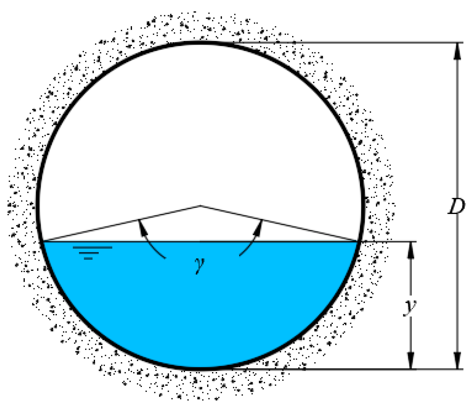
The cross-section of a circular channel is shown in Figure 1.
where γ is the central angle of the wet perimeter (rad) and D is the channel diameter (m).
Substitute Equations (2)–(4) into Equation (1) to yield the critical flow governing equation of circular sections:
2.1.2. Arched Sections
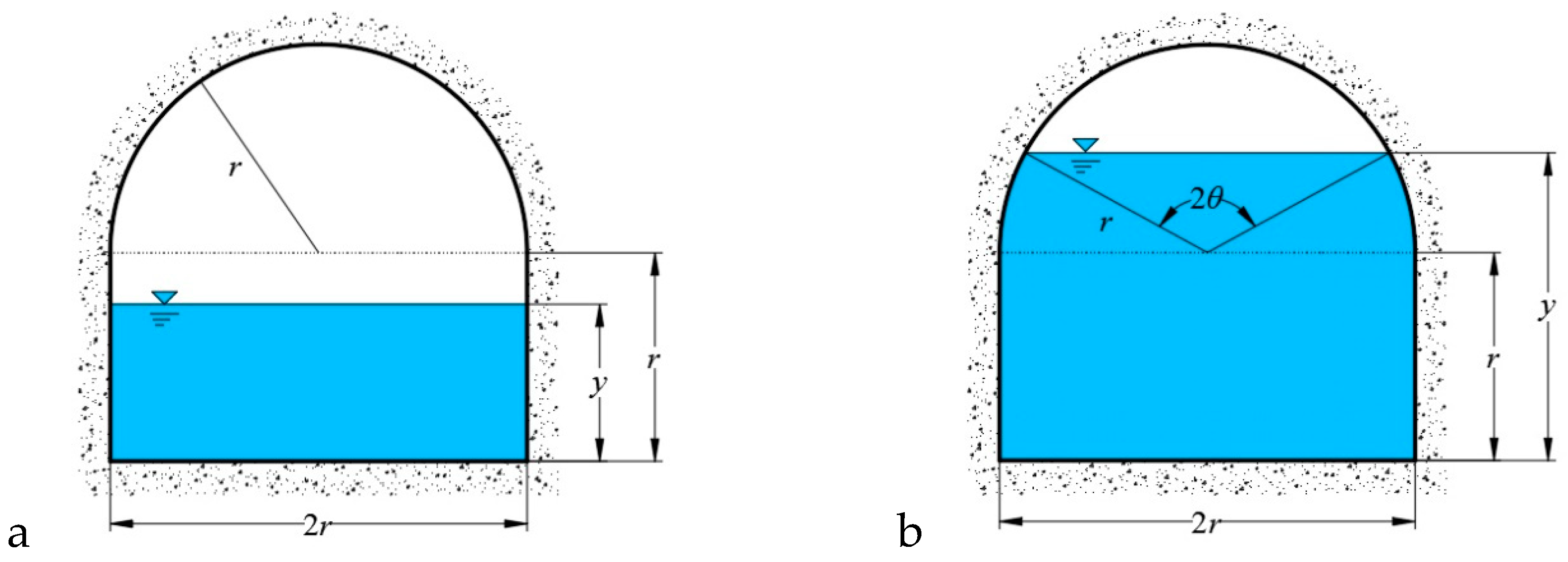
An arched conduit consists of two partitions: The top-arch and the wall on the bottom. The cross-section of an arched conduit is shown in Figure 2.
Geometric properties of the arched section are:
If 0 ≤ y ≤ r,
If r ≤ y ≤ 2r,
where θ is half of the central angle, which corresponds to the wet perimeter (rad); r is the radius of the arch (m); and y is the water depth (m).
Substitute Equations (5)–(7) into Equation (1), yielding the critical flow governing equation of arched sections:
2.1.3. Egg-Shaped Sections
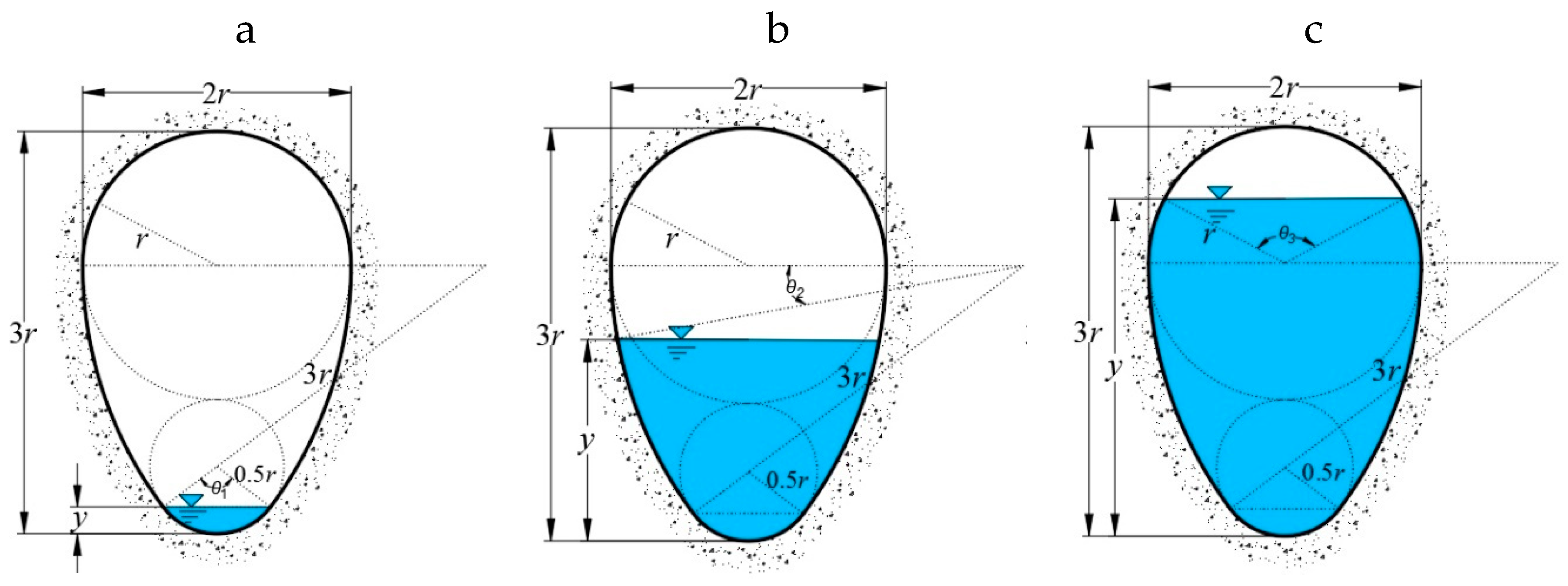
Egg-shaped sections are composed of four arcs, and the radius of each arc is 0.5r, r, and 3r (r is the arch radius, the value of which is obtained from the actual project). Owing to the influence of the process of water delivery and other factors, the height of the water surface may be at the arc with a radius of 0.5r, 3r, or r. The cross-section of an egg-shaped channel is as shown in Figure 3.
The hydraulic parameters of the three types of egg-shaped cross-sections are as follows:
If 0 ≤ y ≤ r/5,
If r/5 ≤ y ≤ 2r,
If 2r ≤ y ≤ 3r,
where θi (i = 1, 2, 3) is the central angle of the corresponding various water depths in rad and y is the water depth in m. On substituting Equations (9)–(11) into Equation (1), the governing equations for the critical depths of egg-shaped sections are obtained:
2.2. Functional Model Construction
According to Equations (4), (8), and (12), because the critical flow equation includes a high-order implicit function, the specific parameters of the discharge section ε and dimensionless relative critical depth η are introduced to simplify the calculation process.
2.2.1. Circular Sections
Introduce the specific parameters of the cross-section:
Dimensionless relative critical depth:
where yc is the critical depth in a circular section, m.
In addition, γ = 2arccos(1 − 2ηc), so Equation (8) can be worked out as follow:
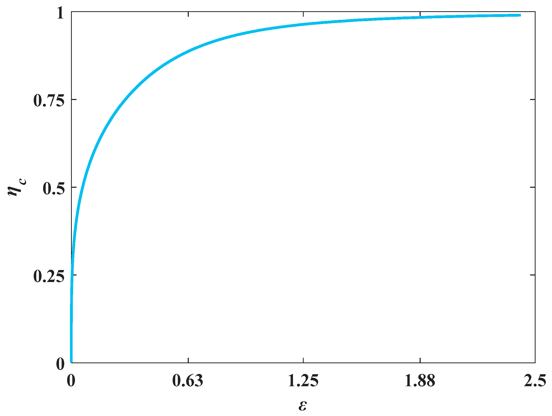
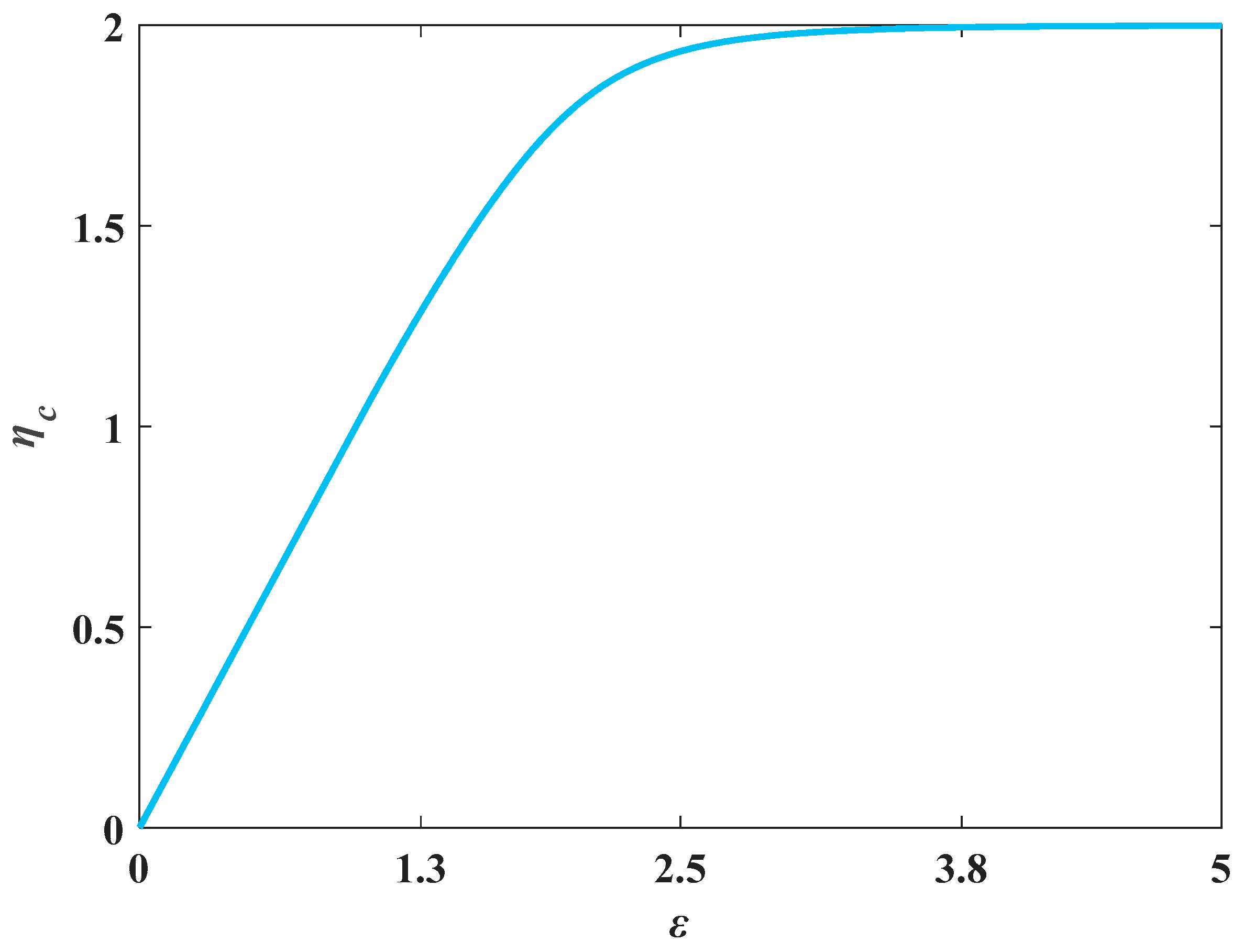
To find the inverse-function model of εc = f(ηc), consider the endpoints of the curve of εc = f(ηc). Obtain the limit via Equation (16):
By the property of the inverse function:
Based on the shape of Figure 4, consider the two limit conditions of Equation (17) and establish three function models as follows:
2.2.2. Arched Sections
Introduce the characteristic parameters of the discharge section:
In addition, the dimensionless relative critical depth is:
where ya is the critical depth in an arched section, m.
Additionally, θ = arccos(ηa − 1), so Equation (8) can be written as:
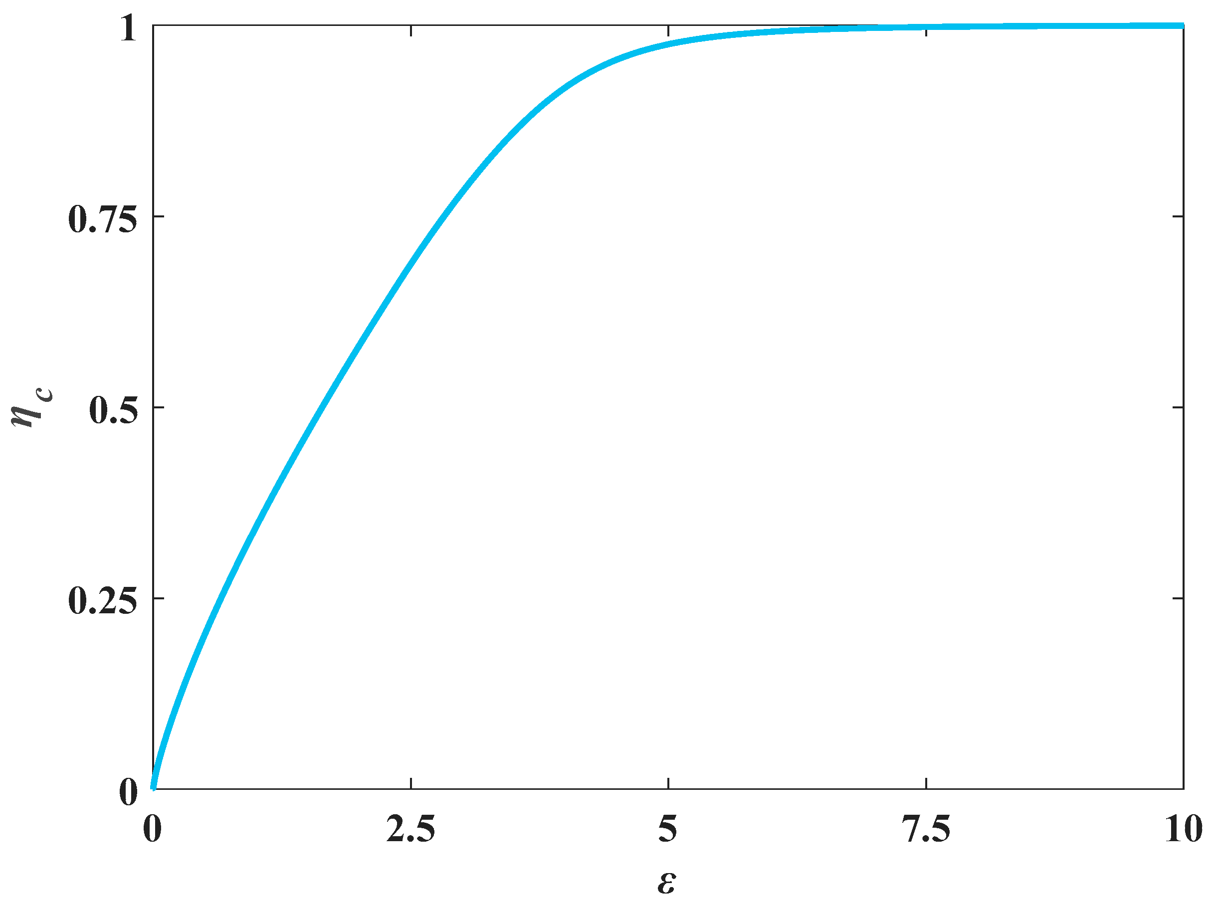
To establish the critical depth function model, observe Figure 5. When the left endpoint ηa = 0, εa = 0; at the same time, when εa = 0, the derivation of 1/f(ηa) is 1. For Equation (20), when the left endpoint is ηa = 0, we get εa = 0; when the right endpoint is ηa = 2, the value of ηa is greater than the critical point of the transient mixed free-surface-pressure flow in the process of water diversion, so neglect ηa = 2. Meanwhile, when ηa = 0, the derivation of εa = f(ηa) is 1. According to the properties of the inverse function, the following is obtained:
Then, construct a math model:
2.2.3. Egg-Shaped Sections
Similarly, introduce the characteristic parameters of the discharge section:
Additionally, the dimensionless relative critical depth is:
where ye is the significant depth in the egg-shaped section, m.
Moreover, based on the relation between θi (i = 1, 2, 3) and y, Equation (8) can be rewritten as follows:
After multiple attempts, it is found that the fraction equation is the precise function model. The function model of an egg-shaped section conduit is established as follows:
2.3. The Fitting Parameter to Establish the Formula
A revised particle swarm optimization (PSO) algorithm is adopted to resolve the high-order piecewise implicit function (Equations (18), (23), and (27)). The PSO algorithm is an evolutionary computing technology proposed by Eberhart and Kennedy in 1995. It is a type of intelligent model inspired by the regularity of a bird group’s collective activities. In the PSO algorithm—which is based on the study of the predatory behavior of a bird cluster—by using the information shared by individuals in the group, the movement of the entire group evolves from that of disorder to order in the problem-solving space, and the optimal solution is finally obtained.
The PSO algorithm, which is a type of iterative optimization algorithm, is similar to a genetic algorithm. The system is initialized to several random solutions. The optimal solution is searched for via iterations wherein the particles share information. Its core steps are as follows:
where is the velocity of the d-th dimension of particle I in the k-th iteration; is the position of the d-th dimension of a particle I in the k-th iteration; I = 1, 2, 3,..., M (population size); w is the inertial weight; c1 and c2 are learning factors; rand1 and rand2 are random numbers between 0 and 1; is a position at which a particle I is located at the individual extremum point of the d-th dimension; and is the position of the global extremum of the entire population in the d-th dimension.
Wu [22] used the PSO algorithm with particle release to improve the efficiency of the PSO algorithm. The specific method is as follows: When the population optimization of the detected algorithm does not update within a certain number of steps, consider that the algorithm is stalled in the search for the optimization, and the global searching ability of the optimal particle is the worst. One should release it to the boundary of the search space, improve the searchability of the algorithm, and exit the idle state to improve the searchability of the current optimal particle.
where is the position of the d-th dimension of the optimal particle, is the velocity of the d-th dimension of the optimal particle, is the upper limit of the d-th dimension space, and is the lower limit of the d-th dimension space.
After the optimal particle is released, if there is no change in the population optimization within a certain number of steps, the algorithm rereleases the current optimal particle to increase the diversity of the population. To some extent, release of the optimal particle improves the problem, as the population cannot escape after falling into the local optimum in the iterative process, which reduces the number of invalid iterations. If the PSO algorithm is applied to establish the direct solution of the circular, arched crossing, and egg-shaped sections, the efficiency and optimization ability can be improved.
The process of the fitting formula for each section is as follows:
2.3.1. Circular Sections
First, determine the fitting range of the dimensionless relative critical water depth ηc and characteristic parameter εc of the overwater section of the circular section. The minimum value of ηc is 0 in theory, but when the water depth is 0, the calculation of the critical depth is meaningless. Thus, the dimensionless relative critical depth ηc is limited to 0.005 to facilitate the application of the formula to small flow calculations. Based on the research of Swamee [3], a maximum value of ηc of 1.0 is adopted. On substituting ηc into Equation (16), obtain the range of εc as 0–+∞.
Then, implement the revised PSO algorithms in MATLAB. Optimize the value of parameters ηc and εc in the set range. Repeatedly implement Equations (28) and (29), and when the algorithm stagnates to the optimization range, the particles are released using Equation (30). Test and compare the three constructed functional models of circular section in Equation (18). The absolute value of the maximum relative error obtained using models I and II is more than 1%, which does not meet the functional requirements of the project. The maximum error of the optimal solution obtained using model III is only 0.182%, and the parameters are a = 1.6692, b = 0.7690, c = 0.6602, d = 0.8990, and e = 1.0000. So we select model III as the final formula form of circular section.
The formula can be expressed as follows:
2.3.2. Arched Sections
First, the dimensionless relative critical depth ηa and the characteristic parameters of the cross-section of conduit εa are scoped. The minimum value of ηa is 0 in theory, but the calculation of the critical depth is meaningless when the water depth is 0. In this article, let the lowest limit of ηa be 0.01. In theory, the maximum value of ηa is 2. However, to prevent the occurrence of transient mixed free-surface-pressure flow in the process of water diversion, it is necessary that the clearance area above the free surface of the conduit be greater than 15% of the total cross-section area. Take the starting point ηa of the transient mixed free-surface-pressure flow as 1.64 in the arched section, and thus set the fitting upper limit of ηa as 1.64. Therefore, the range of the dimensionless water depth ηa is 0.01–1.64. On substituting ηa into Equation (21), obtain the range of εa as 0.01–1.64.
As in the process of fitting the model parameters for a circular section, implement the revised PSO algorithms in MATLAB for an arched section. Repeatedly implement Equations (28) and (29), and when the algorithm stagnates to the optimization range, the particles are released using Equation (30). Finally, the optimal solution combination of the model parameters is found to be a = 0.0602, b = 6.5426, c = 0.0605, and d = 5.7161, and the maximum relative error value is 0.06%. The formula can be expressed as follows:
2.3.3. Egg-Shaped Sections
First, determine the fitting range of the dimensionless relative critical water depth ηe and characteristic parameter εe of the overwater section. In theory, the maximum value of ηe is 1. However, to avoid a transient mixed free-surface-pressure flow in the process of the water diversion, it is necessary that the clearance area above the free surface of the conduit be greater than 15% of the total cross-section area. Therefore, set the fitting upper limit of ηe as 0.82. The minimum ηe is 0 in theory, but the calculation of a critical depth is meaningless when the water depth is 0. In this article, the lowest limit of ηe is determined to be 0.05. Therefore, the range of dimensionless water depth ηe is 0.05–0.82. On substituting ηe into Equation (26), we obtain the range of εe as 0.02–3.03.
As in the process of fitting model parameters for the previous sections, implement the revised PSO algorithms in MATLAB. Determine the values in the range of ηe and εe. Repeatedly implement Equations (28) and (29), and when the algorithm stagnates to the optimization range, the particles are released using Equation (30). Finally, the optimal solution combination of the model parameters is as follows: a = 0.324, b = 0.755, c = 0.22, d = 3.241, e = −0.02, f = 1.162, g = −0.262, h = 1.152, I = 0.788, and j = 2.144. The formula can be expressed as:
3. Results
This paper focuses on the study of the mathematical characteristics of critical depth control equations in circular sections, arched crossing, and egg-shaped sections; constructing the fitting function model with the constraint conditions of the endpoints and derivatives of the equation curve, a general calculation form is obtained, and interpartition calculation can be avoided. Implement the revised PSO algorithms in MATLAB and obtain the right formula for the critical depths in different types of sections of conduits; see Table 1.
4. Discussion
Circular, arched, and egg-shaped sections are often used in non-pressure conduits in hydraulic engineering, agriculture irrigation, and sewerage works. To eliminate the shortcomings of the computation, narrow scope of application, and low calculation accuracy in various sections, this article establishes a function model based on the basic uniform flow formula.
4.1. Formula Evaluation
It is necessary to evaluate the accuracy of Equations (31)–(33) to verify the correctness of the formulas and investigate the entire distribution of errors in the range of application.
4.1.1. Circular Sections
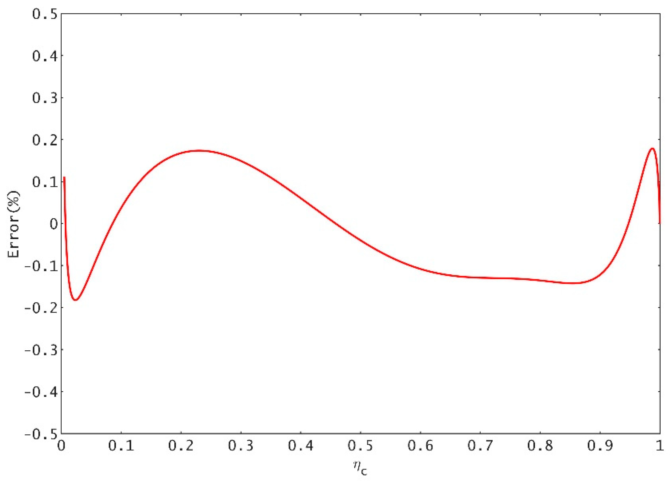
To verify the correctness of Equation (18) and examine the error distribution throughout the application range, consider a series of values in the range of ηc and then substitute these values into Equation (15). To calculate the value of εc, substitute εc into Equation (18). To obtain the approximate calculation value of ηc, set the exact value of the relative water depth ηc as and the relative error . Figure 3 shows the entire distribution of the errors of Equation (31) in the range of application. According to the error analysis, the relative error absolute value of Equation (31) in the commonly used engineering range is less than 0.182%, and the accuracy of the formula fully meets the actual engineering requirements.
Figure 7 shows that, when Equation (31) is used in the practical scope, the value of the relative error is usually within a scope that oscillates near zero; it also illustrates that each parameter combination in Equation (31) is the optimal solution and that the maximum relative error is less than 0.182%, which indicates that the accuracy can meet the demands of practical engineering.
In Table 2, the three formulas for calculating the critical depth of the circular section can be applied to the commonly used range of engineering, and the upper limit can meet the water depth limit of the circular section. Vatankhah’s formula is complicated and is not convenient to calculate. The maximum relative error within the applicable range of the formula is higher than that of the formula in this paper. The formula presented by Swamee is the power exponent function form formula, which simplifies the calculation form compared with Vatankhah’s formula, but the maximum relative error of the calculation formula is exceptional. Based on previous studies, the formula in this paper is more concise and dramatically improves the calculation accuracy. The maximum relative error of the formula within the scope commonly used in engineering is only 0.179%. The formula in this paper is superior to those in other calculation schemes.
4.1.2. Arched Sections
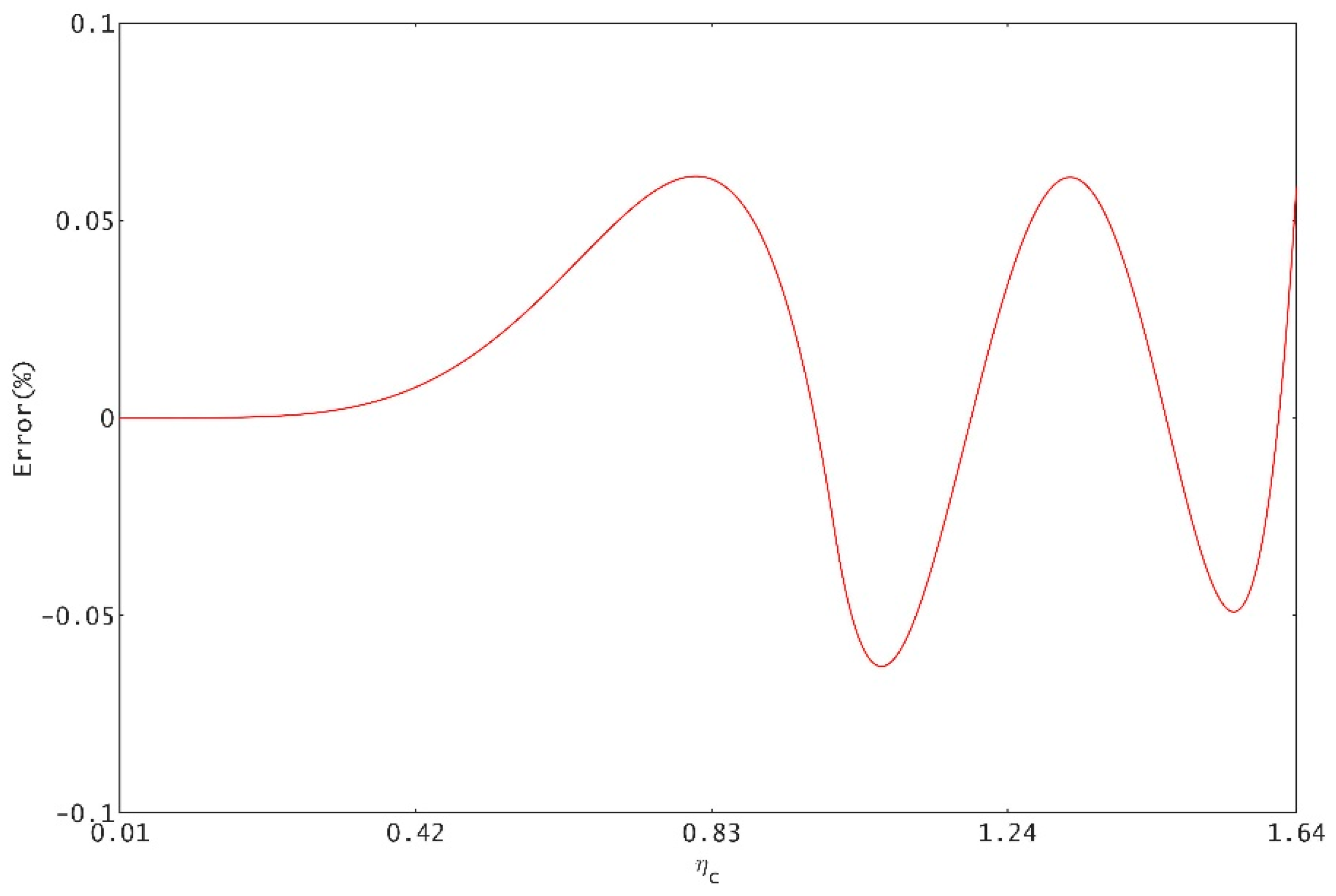
First, extract a series of numerical values in the range of ηa, and then substitute these numerical values into Equation (21) to calculate the value of εa. Then, substitute εa into Equation (32) to obtain the approximate value of ηa. Set the exact value of the relative water depth ηc as and the relative error . Figure 8 shows the entire distribution of the errors of Equation (32) in the range of application. According to the error analysis, the relative error absolute value of Equation (32) in the commonly used engineering range (the ratio of the critical depth to the radius of the crown is between 0.01 and 1.64) is less than 0.06%, the accuracy of the formula fully meets the actual engineering requirements, and the upper limit of the application of the formula can be extended to 0.85 when the maximum error remains unchanged.
Contrast the formulas from previous research in Table 3. Wang’s formula’s form is simple. However, it has a range of application only within the partition of the arch, and the error is significant. Although Vatankhah’s formula avoids piecewise calculation, it is easy to make a calculation error because of its complex form. The formula in this paper is a fraction, and its form is simple. Under the condition of the engineering range, the formula has a direct calculation, and the accuracy of its calculation is the highest. From the full consideration of the formula’s form, application scope, and calculation accuracy, Equation (32) in this paper is considered as the optimal formula for calculating the critical water depth of critical urban portal sections at present.
4.1.3. Egg-Shaped Sections
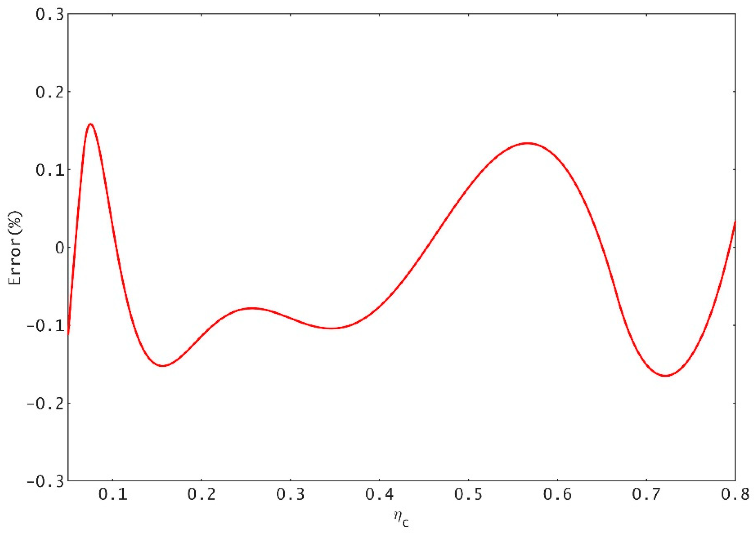
To verify the correctness of Equation (26) and examine the error distribution throughout the application range, consider a series of values in the range of εe and then take substitute these values into Equation (33). To obtain the approximately calculated value of ηe, set the exact value of the relative water depth ηe as and the relative error . Figure 9 shows the entire distribution of the errors of Equation (33) in the application range.
Figure 9 shows that, when Equation (33) is applied in the practical scope (filling degree between 0.05 and 0.82), the value of the relative error is usually within a scope that oscillates near zero; it also illustrates that, in Equation (33), each parameter combination provides an optimal solution, and the absolute value of the maximum relative error is less than 0.17%, which can guarantee the accuracy of the critical depth of the egg-shaped section. The calculation error of the critical water depth is miniscule, and the calculation is convenient for engineering use. The egg-shaped critical depth formula in this paper can be used as a reference for four-arc egg-shaped conduit design.
In Table 4, the three formulas for calculating the critical depth of an egg-shaped section can be applied to the commonly used range of engineering, and the upper limit can meet the water depth limit of an egg-shaped section. Wu’s formula is complicated and is not convenient to calculate. The maximum relative error within the applicable range of the formula is higher than that of the formula in this paper. Teng’s formula is the power exponent function form formula, which simplifies the calculation form compared with Wu’s formula, but the maximum relative error of the calculation formula is exceptional. Based on previous studies, the formula in this paper is more concise and dramatically improves the calculation accuracy. The maximum relative error of the formula within the scope commonly used in engineering is only 0.17%. The formula in this paper is superior to those in other calculation schemes.
4.2. Engineering Verification
The following illustrates the application of the new equations proposed in this paper.
4.2.1. Circular Sections
A diversion conduit is constructed in the hydroelectric project in China, which adopts circular sections. The diameter D = 10 m. In this case, when the discharge Q1 = 0.08 m3/s and Q2 = 200 m3/s, the critical depth can be calculated using the following procedures.
When Q1 = 0.08 m3/s, substitute the factors into Equation (13), which yields:
On substituting this into Equation (31), one obtains:
Therefore, the critical depth is yc = ηc × D = 0.0862 m.
The exact solution is yc = 0.0862 m, and the relative error Δ = −0.0573%.
When Q2 = 200 m3/s, similarly,
On substituting this into Equation (31), we obtain: ηc = 0.4510. Therefore, through multiple iterations, we obtain the critical depth as yc = ηc × D = 4.5101 m.
The exact solution is 4.5097 m, and the relative error Δ = 0.0076%.
4.2.2. Arched Sections
A diversion conduit is used in an agricultural irrigation project, which adopts an arched section. The radius of the crown channel is 2.0 m when discharge Q1 = 8 m3/s and Q2 = 50 m3/s; the critical depth can be calculated using the following procedures.
With the given factor Q1 = 8 m3/s, substituting the factors into Equation (19) yields:
On substituting ε into Equation (32), the following is obtained:
Therefore, through multiple iterations, we obtain that the critical depth is ya = ηa × r = 0.7418 m, the exact solution yc is 0.7418 m, and the relative error is 0%.
With the given factor Q2 = 50 m3/s, one can obtain that:
On substituting Equation (32), ηa = 1.2483 is obtained. Thus, through multiple iterations, we obtain the critical depth as ya = ηa × r = 2.4965 m, the exact solution ya as 2.4956 m, and the relative error as 0.0382%.
According to the results above, under the design conditions of 8 m3/s and 50 m3/s, the critical depth is, respectively, located in the wall and crown of the conduit; this demonstrates that the critical depth in Equation (32) is common to the wall and crown of the conduit in arched sections and has high accuracy.
4.2.3. Egg-Shaped Sections
A diversion conduit is constructed in the hydroelectric project, which adopts an egg-shaped section. The arch radius r = 10 m. In this case, when the discharge Q1 = 0.5 m3/s, Q2 = 10 m3/s, and Q3 = 100 m3/s, the critical depth can be calculated using the following procedures.
When Q1 = 0.5 m3/s, substitute the factors into Equation (24), which yields:
Introduce εe into Equation (33):
Obtain the critical depth ye = ηe × 3r = 0.3273 m, and through multiple iterations, obtain that ye = 0.3275 m and that the relative error Δ = −0.0449%.
When Q2 = 10 m3/s, substitute the factors into Equation (24), which yields:
Introduce εe into Equation (33); similarly, obtain that ηe = 0.2569 and the critical depth ye = ηe × 3r = 1.5412 m, and through multiple iterations, obtain that yn = 1.5424 m and the relative error Δ = −0.0783%.
When Q3 = 100 m3/s, substitute the factors into Equation (16), which yields:
Introduce εe into Equation (33); similarly, obtain that the value of ηe is 0.8115, so the critical depth ye = ηe × 3r = 4.8691 m, and through multiple iterations, obtain that ye = 4.8644 m and the relative error Δ = 0.8107%.
According to the results above, under the design conditions of 0.5 m3/s, 10 m3/s, and 100 m3/s, the critical depth is, respectively, located in the three partitions of the conduit; this demonstrates that the critical depth in Equation (33) is familiar to all partitions of the conduit in egg-shaped sections and has high accuracy.
5. Conclusions
This paper presents three explicit solutions for critical depth in closed conduits flowing partly full, they are suitable for circular, arched, and egg-shaped sections, respectively. The formulas have been improved in all aspects. The calculation precision is improved; the maximum relative error of the formulas of circular, arched, and egg-shaped sections are only 0.182%, 0.06%, and 0.17%, respectively. The formula form is simple, the physical concept is clear, and the computation is quick and convenient. After engineering verification, all the formulas in this paper can meet the practical needs of engineering.
Moreover, a revised PSO is applied to optimize the model parameters in a hydraulic computation. The presented example proves that the PSO with particle release can be used to search for the optimal solution with high speed and accuracy, and it can act as a useful reference for hydraulic calculations of complex section conduits. Thus, the explicit solution for critical depth in closed conduits flowing partly prove the rationality of the model and provide a new idea for the hydraulic calculation in engineering.
Author Contributions
Conceptualization, H.S.; writing—original draft preparation, H.S.; resources, K.Z. and S.X.; writing—review and editing, L.Z. and K.Z.; All authors read and approved the paper.
Funding
This research was supported financially by the National Natural Science Foundation of China [Grant No. 51579214, 41877076], the Fundamental Research Business Expenses of Central Universities [2452017321], the Science and Technology Project of Yangling Demonstration Zone [2017NY-03].
Acknowledgments
I would like to express my gratitude to Jingwen Wang, Aoting Pu, PengLing and JieYang, who have provided me with important help in the stage of submission and revision.
Conflicts of Interest
The authors declare there is no conflicts of interest regarding the publication of this paper.
Abbreviations
The following symbols are used in this paper.
| A | discharge section area; |
| a | model parameter; |
| b | model parameter; |
| c | model parameter; |
| D | channel diameter; |
| d | model parameter; |
| e | model parameter; |
| f | model parameter; |
| g | acceleration due to gravity (9.8 m/s2); |
| j | model parameter; |
| Q | flow discharge; |
| r | radius of crown; |
| T | water width (m); |
| y | water depth in conduit; |
| yc | critical depth in circular sections; |
| ya | critical depth in arched crossing-sections; |
| ye | critical depth in egg-shaped sections; |
| α | velocity distribution coefficient |
| εc | characteristic parameter of overwater section in circular sections; |
| εa | characteristic parameter of overwater section in arched crossing sections; |
| εe | characteristic parameter of overwater section in egg-shaped sections; |
| γ | central angle of the wet perimeter; |
| θ | half central angle of the wet perimeter in circular sections; |
| θi | central angle of different water depths corresponding to egg-shaped sections; |
| dimensionless relative water depth in circular sections; | |
| dimensionless relative water depth in arched crossing sections; | |
| dimensionless relative water depth in egg-shaped sections. |
References
- Wang, Z.Z.; Chen, T.; Zhang, X.M.; Zhang, X.D. Approximate solution for the critical depth of an arched tunnel. J. Tisnghua Univ. (Sci. Technol.) 2004, 44, 812–814. [Google Scholar]
- Raikar, R.V.; Reddy, M.S.S.; Vishwanadh, G.K. Normal and critical depth computations for egg-shaped conduit sections. Flow Meas. Instrum. 2010, 21, 367–372. [Google Scholar] [CrossRef]
- Swamee, P.K. Critical depth equations for irrigation canals. J. Irrig. Drain. Eng. 1993, 119, 400–409. [Google Scholar] [CrossRef]
- Swamee, P.K. Critical depth equations for irrigation canals. J. Irrig. Drain. Eng. 1994, 120. [Google Scholar] [CrossRef]
- Terzidis, G. Explicit method for calculating critical depth of trapezoidal openchannel flow. Hydrotechika J. Hell. Hydrotech. Assoc. 2003, 13, 105–112. [Google Scholar]
- Terzidis, G. Explicit method for calculating uniform depth of trapezoidal openchannel flow. In Proceedings of the 5th National Conference of Greek Association of Water Resources Management, Xanthi, Greece, 6–9 April 2005; pp. 239–245. [Google Scholar]
- Wang, Z. Formula for calculating critical depth of trapezoidal open channel. J. Hydraul. Eng. 1998, 124, 90–91. [Google Scholar] [CrossRef]
- Manoj, K.C.; Devkota, J.; Fang, X. Comprehensive evaluation and new development of determination of critical and normal depths for different types of open-channel cross-sections. In Proceedings of the World Environmental and Water Resources Congress, Providence, RI, USA, 16–20 May 2010; pp. 2058–2068. [Google Scholar]
- Vatankhah, A.R.; Bijankhan, M. Choke-free flow in circular and ovoidal channels. Water Manag. 2010, 163, 207–215. [Google Scholar] [CrossRef]
- Vatankhah, A.R.; Easa, S.M. Explicit solutions for critical and normal depths in channels with different shapes. Flow Meas. Instrum. 2011, 22, 43–49. [Google Scholar] [CrossRef]
- Vatankhah, A.R. Direct solutions for normal and critical depths in standard city-gate sections. Flow Meas. Instrum. 2012, 28, 16–21. [Google Scholar] [CrossRef]
- Liu, J.L.; Wang, Z.Z. Explicit equations for normal and critical depths of standardcity-gate cross section tunnels. Proc. Inst. Civ. Eng. Water Manag. 2019, 166, 199–206. [Google Scholar] [CrossRef]
- Zhao, Y.; Song, S.; Meng, Q. Approximate method calculating critical water depth in common city-opening shaped cross-section. Eng. J. Wuhan Univ. 2009, 25, 14–15. [Google Scholar]
- Liu, J.L.; Wang, Z.Z.; Leng, C.J.; Zhao, Y.F. Explicit equations for critical depth in open channels with complex compound cross sections. Flow Meas. Instrum. 2012, 24, 13–18. [Google Scholar] [CrossRef]
- Bijankhan, M.; Kouchakzadeh, S. Egg-shaped cross section: Uniform flow direct solution and stability identification. Flow Meas. Instrum. 2011, 22, 511–516. [Google Scholar] [CrossRef]
- Bureau of Indian Standards. IS-4880: Indian Standard Code of Practice for Design of Tunnels Conveying Water Part (II); Bureau of Indian Standards: New Delhi, India, 1976.
- Swamee, P.K.; Rathie, P.N. Exact equations for critical depth in a trapezoidal canal. J. Irrig. Drain. Eng. 2005, 131, 474–476. [Google Scholar] [CrossRef]
- Shirley, E.D. Critical-depth calculations in complex channel sections. J. Irrig. Drain. Eng. 1991, 117. [Google Scholar] [CrossRef]
- Patil, G.P.; Murthy, J.S.; Ghosh, L.K. Uniform and critical flow computations. J. Irrig. Drain. Eng. 2005, 131, 375–378. [Google Scholar] [CrossRef]
- Patil, G.P.; Vasant, N.D.; Rajnikant, M.K. Integrating equation of gradually varied flow. J. Hydraul. Eng. 2001, 127, 624–625. [Google Scholar] [CrossRef]
- Chow, V.T. Integrating the equation of gradually varied flow. Proc Pap. Am. Soc. Civ. Eng. 1955, 81, 1–32. [Google Scholar]
- Wu, Z.-K.; Yang, Q.-Z.; Shi, Y.-Q.; Li, Y.-F. Particle swarm optimization with particle release and speed limit. Appl. Res. Comp. 2013, 30, 682–683. [Google Scholar]
Figure 1.
Cross-section of a circular conduit.

Figure 2.
Cross-section of an arched conduit ((a) 0 ≤ y ≤ r, (b) r ≤ y ≤ 2r)).

Figure 3.
Cross-section of an egg-shaped conduit ((a) 0 ≤ y ≤ r/5, (b) r/5 ≤ y ≤ 2r, (c) 2r ≤ y ≤ 3r).
Figure 3.
Cross-section of an egg-shaped conduit ((a) 0 ≤ y ≤ r/5, (b) r/5 ≤ y ≤ 2r, (c) 2r ≤ y ≤ 3r).

Figure 4.
The relation curve between ε and ηc functions of circular section.

Figure 5.
The relation curve between the ε and ηa functions of the arched section.

Figure 6.
The relation curve between the ε and ηe functions of an egg-shaped section.

Figure 7.
Error analysis of the critical depth formula for circular sections.

Figure 8.
Error analysis of the critical depth formula for arched sections.

Figure 9.
Error analysis of the critical depth formula for egg-shaped sections.


Table 1.
The formulas of critical depths for three types of sections.
| Type of Sections of Conduits | Formula Form | Range (ηn) | Maximum Error/% |
|---|---|---|---|
| Circular section | 0.005–1 | 0.182 | |
| Arch section | 0.01–1.64 | 0.06 | |
| Egg-shaped section | 0.05–0.82 | 0.17 |
Table 2.
The comparison of different formulas for the critical depth of a circular section.
| Formula | Formula Form | Range (ηn) | Maximum Relative Error/% |
|---|---|---|---|
| Vatankhah and Easa (2011) | [0.02,1.0] | 1.464 | |
| Vatankhah (2012) | [0,0.92] | 0.249 | |
| Proposed | [0.005,1] | 0.182 |
Note: , R is the radius of the conduit .
Table 3.
The comparison of different formulas for the critical depth of standard arched sections.
| Formula | Formula Form | Range (ηc) | Maximum Relative Error/% |
|---|---|---|---|
| Wang (1998) | 1.10–1.80 | 0.50 | |
| Vatankhah (2012) | 0.01–1.64 | 0.07 | |
| Proposed | 0.01–1.64 | 0.06 |
Note: , , , .
Table 4.
The comparison of different formulas for the critical depth of an egg-shaped section.
| Formula | Formula Form | Range (ηn) | Maximum Error/% |
|---|---|---|---|
| Wu | 0.0667–0.85 | 0.91 | |
| Teng | 0.05–0.80 | 0.649 | |
| Proposed | 0.05–0.82 | 0.17 |
© 2019 by the authors. Licensee MDPI, Basel, Switzerland. This article is an open access article distributed under the terms and conditions of the Creative Commons Attribution (CC BY) license (http://creativecommons.org/licenses/by/4.0/).
Share and Cite
MDPI and ACS Style
Shang, H.; Xu, S.; Zhang, K.; Zhao, L. Explicit Solution for Critical Depth in Closed Conduits Flowing Partly Full. Water 2019, 11, 2124. https://doi.org/10.3390/w11102124
AMA Style
Shang H, Xu S, Zhang K, Zhao L. Explicit Solution for Critical Depth in Closed Conduits Flowing Partly Full. Water. 2019; 11(10):2124. https://doi.org/10.3390/w11102124
Chicago/Turabian StyleShang, Haixin, Song Xu, Kuandi Zhang, and Luyou Zhao. 2019. "Explicit Solution for Critical Depth in Closed Conduits Flowing Partly Full" Water 11, no. 10: 2124. https://doi.org/10.3390/w11102124
Note that from the first issue of 2016, this journal uses article numbers instead of page numbers. See further details here.