Numerical Analysis on Hydrodynamic Characteristics of Surface Piercing Propellers in Oblique Flow

1
College of Naval Architecture and Ocean Engineering, Naval University of Engineering, Wuhan 430033, China
2
School of Naval Architecture, Ocean and Civil Engineering, Shanghai Jiao Tong University, Shanghai 200240, China
3
Weichai Power Co., Ltd., Weifang 261061, China
*
Author to whom correspondence should be addressed.
Water 2019, 11(10), 2015; https://doi.org/10.3390/w11102015
Submission received: 26 July 2019
/
Revised: 18 September 2019
/
Accepted: 19 September 2019
/
Published: 27 September 2019
(This article belongs to the Section Hydraulics and Hydrodynamics)
Abstract
:When a planing boat sails at the free surface, the posture changes drastically with time, so the surface piercing propellers usually work in oblique flow. In this paper, numerical simulations are performed to predict the performance of PSP-841B with Unsteady Reynolds Averaged Navier–Stokes (URANS) method coupling with sliding mesh and volume of fluid (VOF) method. The results show that the predicted thrust and torque coefficients of PSP-841B are in good agreement with the experimental data. It proves the present numerical schemes are feasible and validated. These schemes are applied in the simulations of SPP-1 that is installed to a planing craft. In oblique flow, the ventilation volume of SPP-1 increases dramatically, resulting in the postponed transition of vented status that changes from the fully dry to partially wetted; at the low advance ratios, the thrust and torque coefficients are less than that in the horizontal case. As the advance speed increases, the vented mode of SPP-1 varies from full ventilation to partially wet, and the forces and moments get closer to the results in the horizontal flow. In addition, the blockage effect of air cavity to the inflow in oblique flow is more significant than the results in the horizontal case.
1. Introduction
Surface piercing propellers (SPPs) are increasing in popularity for high-speed crafts. Compared with conventional propellers, surface piercing propellers have higher propulsive efficiency. Since the appendages such as shaft and bracket are above the free surface, the appendage resistances are reduced dramatically [1,2]. In addition, surface piercing propellers operate near the free surface, which causes the amount of air to be sucked into the water and the cavitation generation to be inhibited. The floating conditions of planing crafts vary greatly when it comes to higher speeds, especially the large pitch. Under these situations, the surface piercing propellers usually operate in oblique flow.
The studies of hydrodynamic characteristics of surface piercing propellers mainly rely on experiments. A series of surface piercing propellers were utilized to study the ventilation state by Hadler and Hecker [3] in 1968. Misra and Gokarn et al. [4] found that the wedge section profile made the open water performance of surface piercing propellers more excellent, and its reversing performance was also better. Ferrando and Scamardella et al. [5] conducted both model and real ship tests for surface piercing propellers. In their model tests, the propulsion efficiency increased by 10–15%. Chudley and Grieve et al. [6] analyzed the effects of some parameters such as the form of trailing edge and immersion ratio on hydrodynamic performance of surface piercing propellers. Ding [7] studied the similarity criteria of the surface piercing propellers, and the performance of a series of surface piercing propellers with varying Fourier number, oblique angle and camber. Xia and Li et al. [8] conducted the preliminary analysis on the induced vertical forces acting on the surface piercing propellers.
Although the experiments provide intuitive and reliable results of surface piercing propellers, the experimental research is sometimes time-consuming and costly. Some researchers have tried to analyze the hydrodynamic performance by using theoretical methods. The current theoretical methods on surface piercing propellers are mainly developed from conventional propellers. Furuya [9] used the lifting line theory to predict the open water performance of two partially submerged propellers. In his work, the free surface was taken into consideration by using image method. So, the splashing induced by the entry and exit water of blades was unable to capture. In addition, the thickness of the air cavity attached to the suction side of blades was not considered in this method. Young et al. [10,11,12,13,14] adopted boundary element method to do intensive studies on the open water performance of PSP-841B. The flow details at the leading edges and tips were captured well and the thickness of trailing edges was accounted for. However, the complex phenomena, for example, impact forces generated when blades pierce free surface, the free surface splashing and the breaking of free surface in the flow field, were not obtained in their work.
The development of Computational Fluid Dynamic (CFD) technology makes it possible to study the hydrodynamic characteristics of surface piercing propellers with more detailed information. Caponnetto [15] firstly conducted numerical simulations of surface piercing propellers, and he only presented the time histories of forces acting on a single blade. Alimirzazadeh and Roshan et al. [16] investigated the influence of yawing angle and immersion ratio on the hydrodynamic performance of PSP-841B in the off-design condition by employing the open source platform, OpenFOAM. Their work indicated the PSP-841B produced larger thrust and torque when the immersion ratio increased. Increasing yaw angles lead to decreasing thrust and torque coefficients. Yari and Ghassemi [17] carried out the preliminary study on a wedge with cupped and non-cupped PSP-841B. They found that the cup of the blade sections has significant influence on the hydrodynamic characteristics of SPPs. In their study, the higher thrust and efficiency were produced by the cupped PSP-841B. The predicted results were matched with experimental measurements well at high advance ratios. Himei [18] utilized the vortex lattice method and RANS simulation to predict the effect of the number of blades and the immersion ratio on the open water performance of PSP-841B under unsteady conditions. However, the predicted free surface was not matched with the experiments, which led to larger differences of thrust and torque coefficients. Shi [19] employed the commercial code, Fluent, to investigate the wake and pressure distribution of a surface piercing propeller with five blades. The free surface captured in the simulations was in good agreement with the experimental results. The error of the predicted thrust and torque coefficients was larger with the immersion ratio increasing. Yang and Ren et al. [20] analyzed the hydrodynamic performance of a surface piercing propeller that was ventilated artificially. They found that the artificial ventilation made the thrust and torque coefficients decrease. With the growth of advance ratios, the effect of ventilation on thrust was less than torque, which increased the efficiency of the ventilated SPP. Their study demonstrated that the artificial ventilation was able to improve the hydrodynamic performance of the surface piercing propellers.
Many researchers have studied the hydrodynamic performance, fluctuating characteristics of forces/moments and ventilation state of surface piercing propellers in horizontal flow. However, there are few studies on hydrodynamic performance of surface piercing propellers in oblique flow. In this paper, the hydrodynamic characteristics of surface piercing propeller (SPP-1) in oblique flow is studied by employing the commercial software, Star-CCM+. The numerical schemes based on standard model PSP-841B are applied to predict the hydrodynamic characteristics of SPP-1. We also analyze the open water performance, pressure distributions on the blades, the deformation of free surface and velocity distributions in the wake field of SPP-1.
2. Numerical Method
2.1. Geometry Model
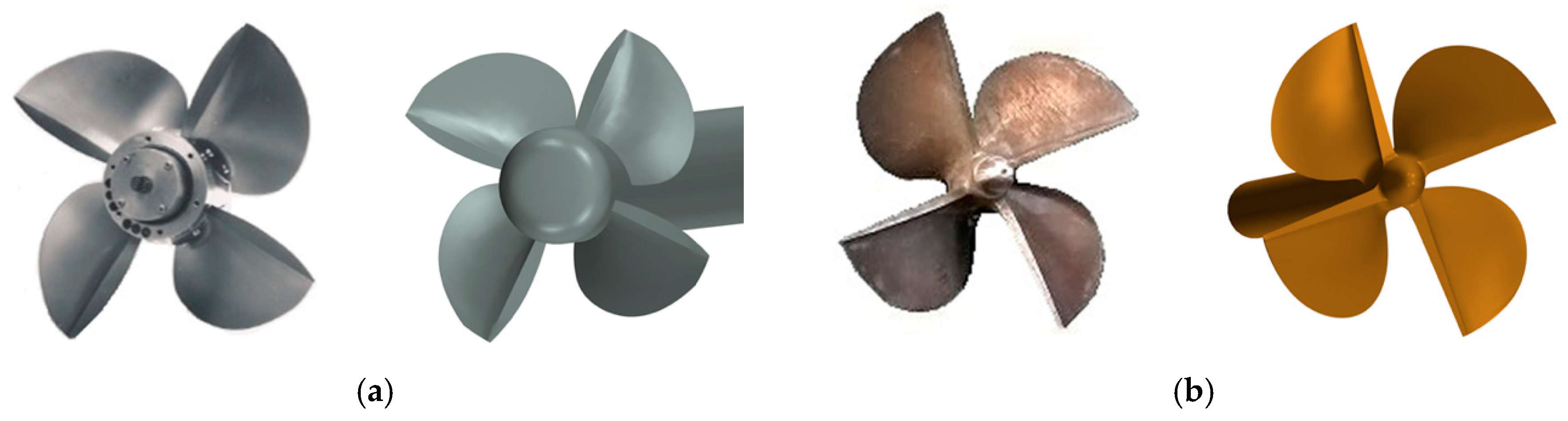
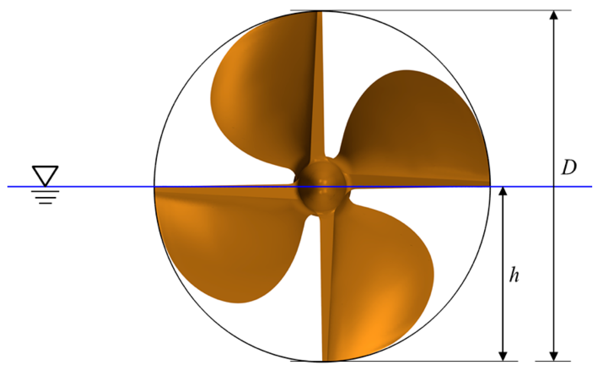
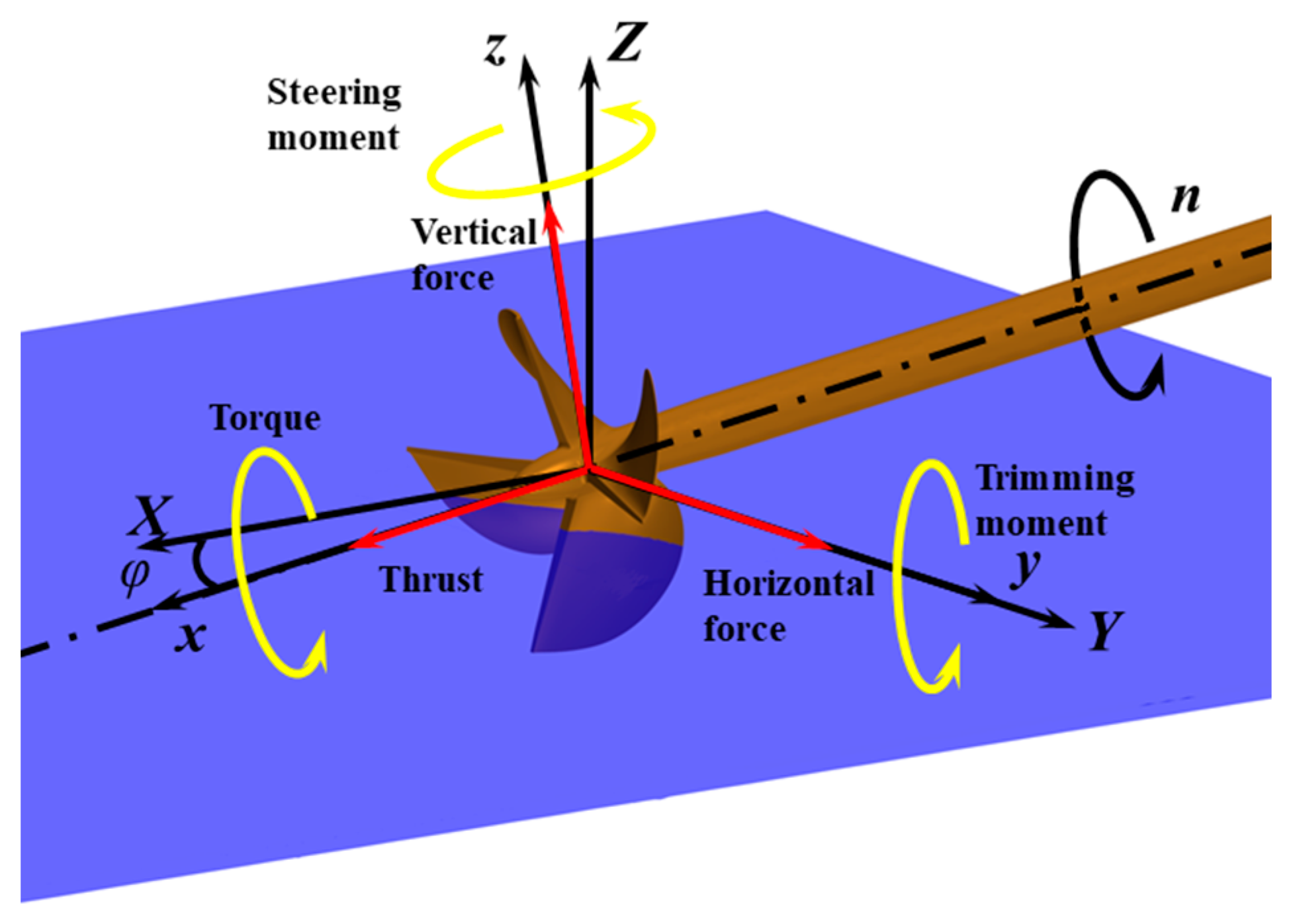
Olofsson [21] carried out hydrodynamic experiments of PSP-841B in the free surface cavitation tunnel at KaMeWa of Sweden in 1996. The planing craft equipped with SPP-1 advanced at a speed of more than 60 kn in the sea trials. The parameters of PSP-841B and SPP-1 are shown in Table 1. Figure 1 shows their 3D model and actual propeller geometry. As shown in Figure 2, the immersion ratio of surface piercing propellers is It = h/D. h represents the distance from blade tip to free surface and D is the diameter of the propeller. The vertical adjustable angle of SPP-1 is ±7°. The hydrodynamic characteristics of SPP-1 are predicted in horizontal flow, φ = 0°, and oblique flow, φ = 7°. φ represents the inclination angle as shown in Figure 3.
As for the propeller operates in oblique flow, the horizontal resultant thrust, TX, and vertical resultant force, FZ, are obtained from the flowing equations:
where Tx and Fz represent the axial thrust and vertical force in local coordinate, respectively.
2.2. Governing Equations
The fact that the surface piercing propellers work near the free surface means the propellers are always in a complex three-dimensional air–water two-phase flow field. In the numerical simulations, the compression of air is not taken into consideration. The governing equations include the mass conservation equation and the momentum equation [22]:
where hf is the film thickness. The volume V and the surface A are functions of the film thickness and its spatial distribution. ρf is the film density, vf is the film velocity, vg is the grid velocity, and the subscript f denotes the fluid film values. The quantity sm is the mass source/sink per unit area. pf is the pressure, fb is the body force, Tf is the viscous stress tensor within the film. sm is the momentum source corresponding to the mass source sm.
The SST k-ω turbulence model is selected to enclose Reynolds Averaged Navier–Stokes (RANS) equation. The model combines the advantages of the k-ε model and the k-ω model, making it possible to simulate more accurately the flow separation of airfoil at high attack angles.
The volume of fluid (VOF) method is adopted to capture the free surface, because this method is more suitable to simulate the strong nonlinear deformation. The basic idea of VOF is to study the ratio of the volume of the different phases in the grid cell to determine the interface.
The transport equation is as follows:
If F = 1, the unit is all water; F = 0, the unit is all air; when 0 < F < 1, the unit includes air and water simultaneously.
Simulations of propeller rotational motion can be performed by using multiple reference frame (MRF) and sliding mesh. However, the MRF method is only suitable for steady predictions of conventional propellers, not for the unsteady simulations. The flow field of surface piercing propellers is an unsteady air–water mixed one, so the sliding mesh method is selected in the present study.
2.3. Grid Generation
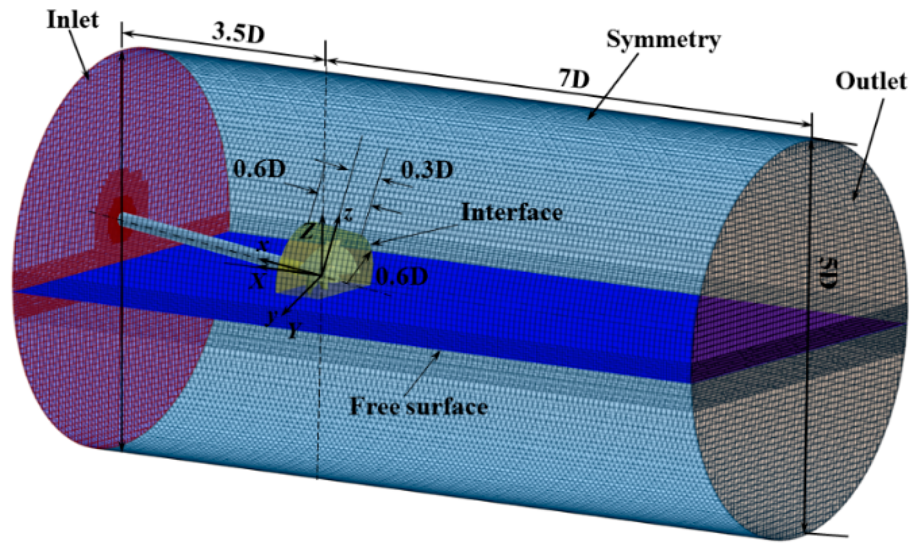
In the numerical simulations, high quality grid not only improves computational efficiency but also ensures computational accuracy. Due to the application of sliding mesh, the computational domain includes rotating and static domains, as shown in Figure 4. The static domain is a cylinder with the diameter of 5.0 D, and the diameter of rotational domain is 1.2 D. The trimmer mesh is selected to discrete the computational domain. The maximum size of the volume grid of the rotating domain is set to 1.2%D. The surface mesh size of the blade is set to 1.2% D. A block is adopted to refine the free surface. Figure 5 shows the local mesh. With the sliding mesh method, the information of the flow field is exchanged through the interface between the static and rotating domains. It is necessary to make the mesh size of the interfaces in the static and rotating domains the same as much as possible. Near the blades surface, the prism layers are added. The following formula [16] is applied to calculate the thickness of the first prism layer, Δy:
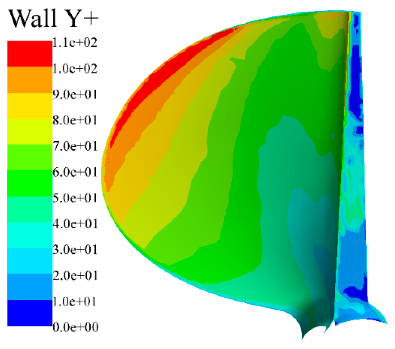
where L is the characteristic length, which is the diameter of the propeller in the present simulations; Re is the flow Reynolds number. The non-dimensional distance y+ on the main blade surface were less than 110, as presented in Figure 6.
2.4. Boundary and Initial Conditions
Since the surface piercing propellers operate near the free surface, the flow field is an unsteady air–water mixed one. The inlet boundary is set as a velocity inlet condition and the outlet boundary is set as a pressure outlet condition with a standard pressure as the reference pressure. The outer boundary of the stationary domain is set as a symmetry plane, and the surfaces of the blades and shaft are the no slip and impermeable wall. The interfaces between the rotating and stationary domain are sliding interfaces. The volume fractions in the flow field are composites that include the volume fraction of water and air. The pressure and the velocity in the flow field are set as the hydrostatic pressure and the velocity of the flat wave respectively. In the simulations, the time step is 3.70 × 10⁻⁵ s, with the surface piercing propeller rotating 0.5 per time step. The time step is chosen to make courant number no more than 1, which is suggested by Blocken and Gualtieri [23].
3. Verification of Numerical Method
3.1. Grid Independence
Grid independence study is very important for numerical simulations. Here, four grids resolution levels are selected to check the mesh sensitivity. The grid convergence study is carried out with the immersion ratio of PSP-841B being 0.33 at J = 0.8 in horizontal flow. The calculated results of thrust and torque coefficients are compared to the experimental values [16] and are presented in Table 2. As we can see, the predicted results get closer to the experimental ones as the grid number increases. However, the more grids mean lower computational efficiency and more time-consuming. So, in this paper, the grid scheme with 3.8 million is employed in the present simulations, with proper accuracy and efficiency.
3.2. Hydrodynamic Performance
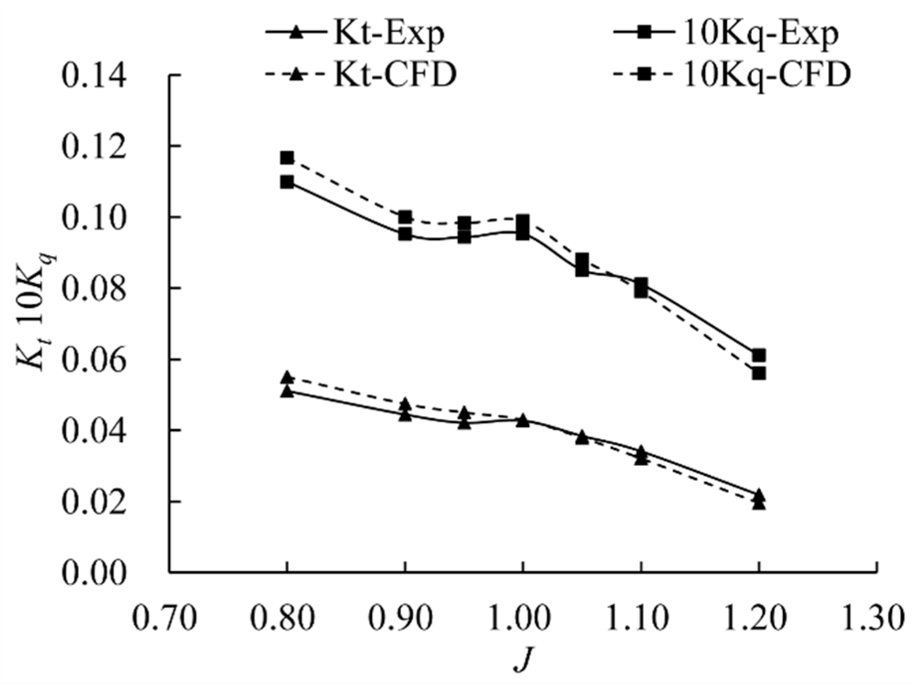
In the numerical simulations of PSP-841B, the different advance ratios J are obtained by varying the advance speed, VA. Figure 7 shows the comparison between the predicted results and experimental data of PSP-841B. As we can see, the calculated values are in good agreement with the experimental ones. With the growth of the advance ratios J, the error of thrust and torque coefficients varies from positive to negative, and the discrepancy near the design point is less than 5%. We can also investigate the transition zone of PSP-841B where the thrust and torque coefficients are unstable when 0.90 < J < 1.0. The predicted results demonstrate that the present numerical schemes are effective and accurate for the prediction of hydrodynamic characteristic of surface piercing propellers. So, the present numerical method is adopted in the simulations of SPP-1.
4. Numerical Results and Analysis
In the simulations, the hydrodynamic performance of SPP-1 is predicted when advance ratios J vary from 0.8 to 1.4 at It = 0.75. The inclination angles of SPP-1 in vertical direction are adjustable from −7° to 7°. Both conditions are selected to analyze the hydrodynamic characteristics of SPP-1 in horizontal and oblique flow, in which the inclination angles are 0° and 7°, respectively.
4.1. Free Surface
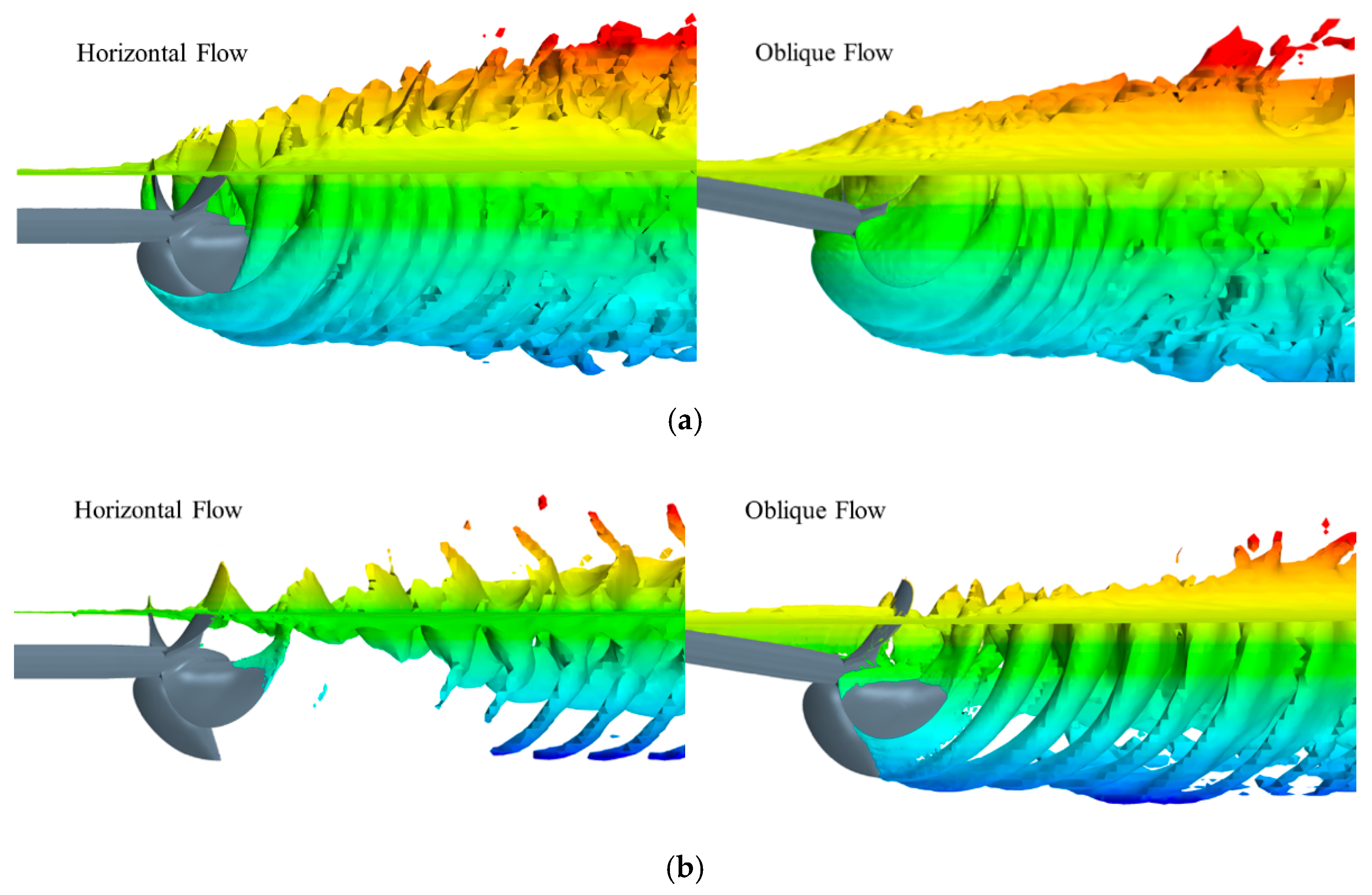
The free surface morphology of SPP-1 is shown in Figure 8. As we can see, only the tips of the blades are ventilated in the horizontal flow while the suction surfaces are completely covered by air in oblique flow at J = 0.8. At the high advance ratio, J = 1.4, the smaller air cavities detach from the tips quickly in the horizontal flow. However, in the oblique flow, the ventilated area of SPP-1 is greater than that in another case, and the air cavities are more complete.
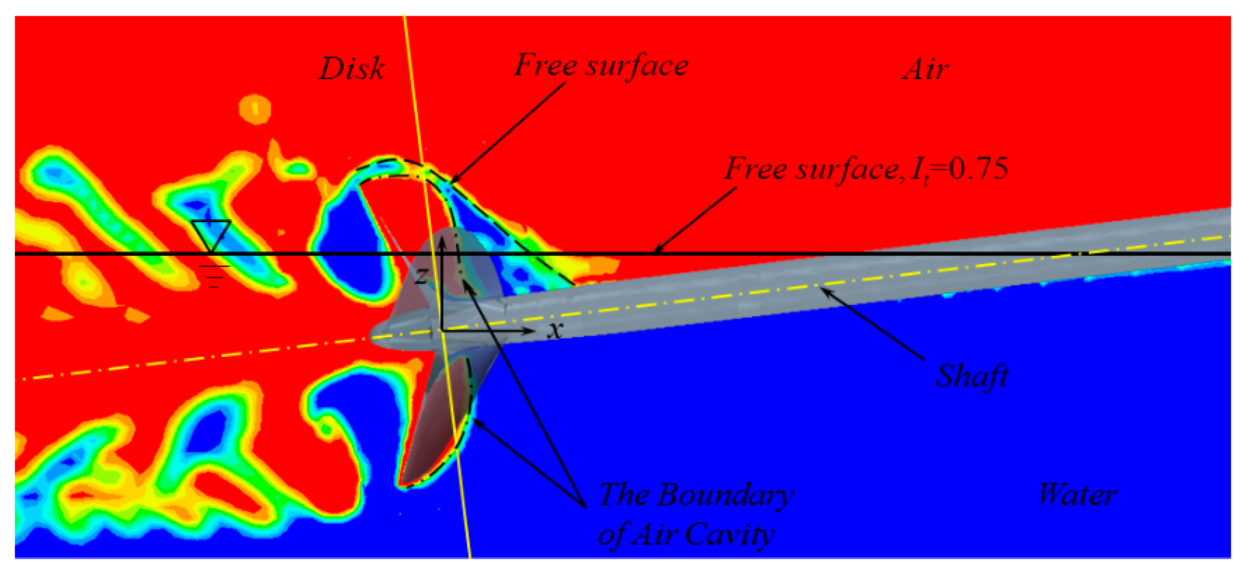
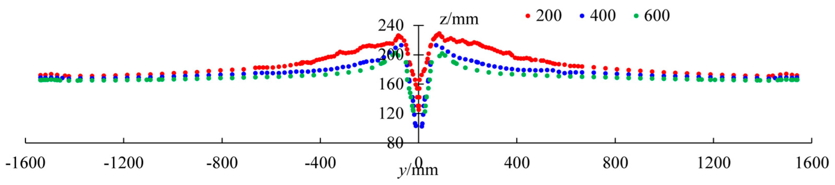
Observing the air-water distribution is helpful to analyze the flow field of surface piercing propellers. So, the predicted results on the xz plane at J = 0.8 are presented in Figure 9. The depression of the free surface occurs above the axis of the propeller. The depression first increases and then decreases in the process of approaching the origin, as shown in Figure 10. In Figure 10, blue, green and red represent the free surface at x = 200 mm, 400 mm and 600 mm in front of the disk, respectively. As we can see, the depression of free surface is the deepest when x = 400 mm; when x = 200 mm, the free surface rises on the contrary since the air cavities of the suction sides block the inflow.
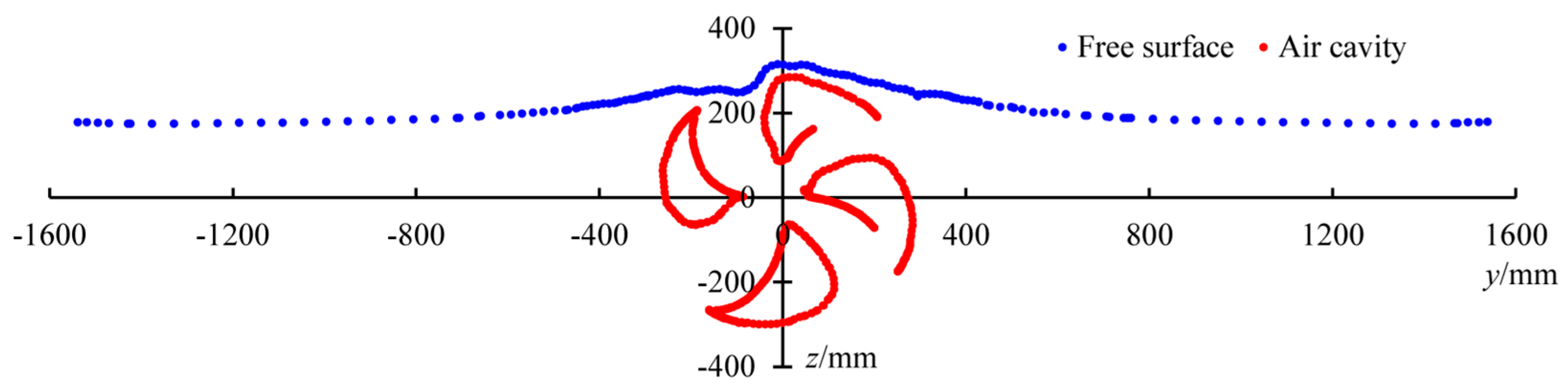
The free surface and air cavities profiles at x = 0 mm are presented in Figure 11. Blue and red represent the free surface and the air cavities on the suction side, respectively. The air cavities are not connected with the free surface in this position, which proves that the air cavities block the inflow. The uplift of the free surface is not symmetrical along the y axis since the SPP-1 is counterclockwise. With left blades piercing the free surface, the air is drawn into the water so that the free surface is lower than the right.
4.2. Hydrodynamic Performance
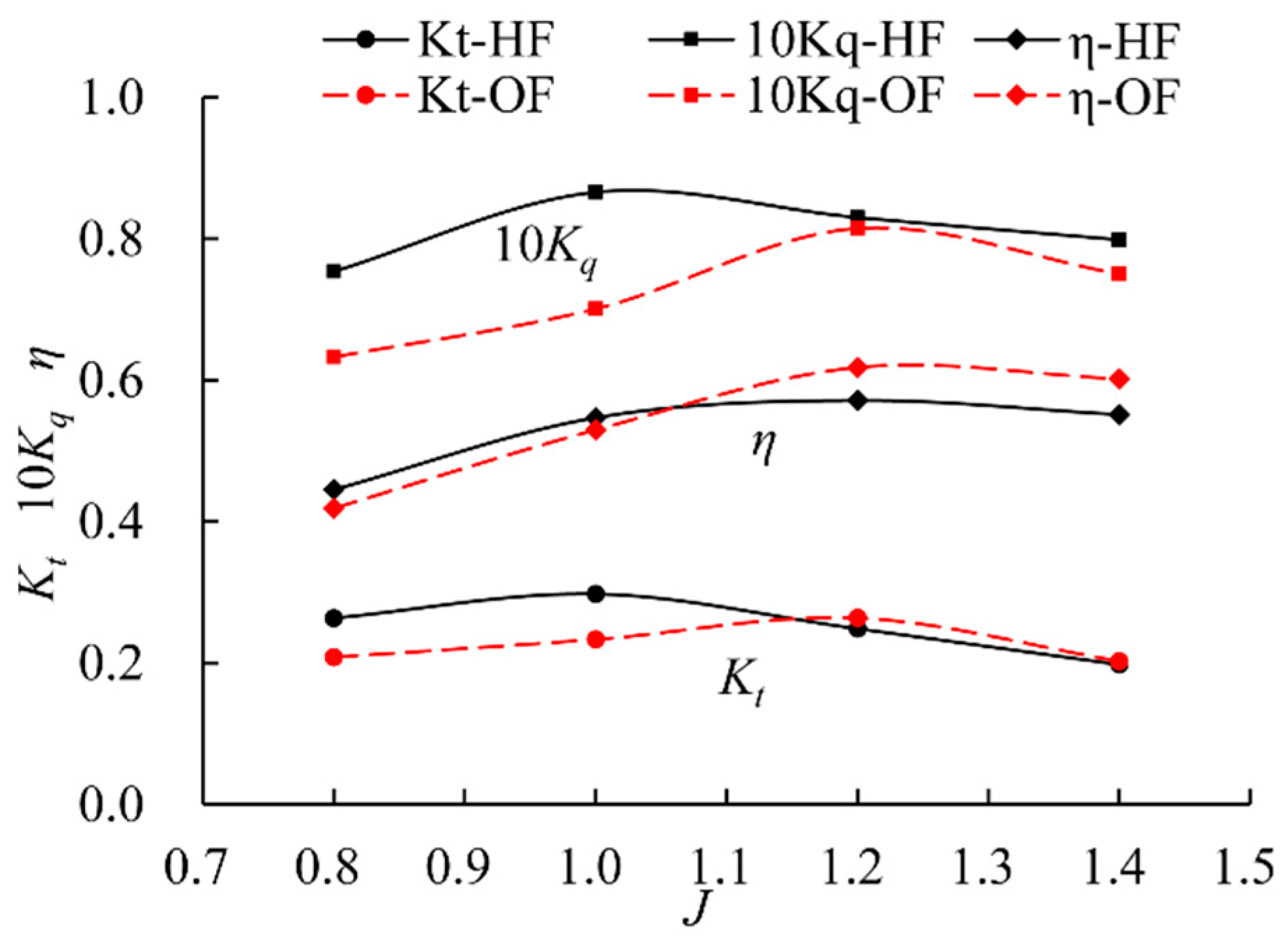
Figure 12 depicts the comparison of the open water performance of SPP-1 in the horizontal and oblique flow. At low advance ratios, J = 0.8 and 1.0, the thrust and torque coefficients are less than the results in horizontal flow. This is because that more air is attached to the blade suction sides and blocks the inflow of the propeller in oblique flow. So, less water flows through the propeller disk and makes thrust and torque less. When advance ratio increases, the ventilation status of SPP-1 varies from fully vented mode to partial vented condition. In the partially vented mode, the tendency of hydrodynamic performance is similar to the results of conventional propellers, which will decrease as advance speed increases. In the oblique flow, the thrust is larger than that in horizontal flow at J = 1.2, while the torque is less. The tendency of Kt and 10 Kq are consistent with the experiments in the literature [7].
Since the surface piercing propellers work near free surface, large forces and moments occur in the lateral and vertical directions. They demand higher requirements on the strength of surface piercing propellers and the maneuverability of high-speed vessels. At low advance ratios, surface piercing propellers are vented fully, and the forces acting on different blades are relative uniform. Therefore, the lateral and vertical forces and moments are little. In oblique flow, the vented area of SPP-1 is larger than another case. So that forces/moments are less than another results at J = 0.8, as shown in Figure 13. KFy and KFz represent the forces in lateral and vertical directions. KMy and KMz represent the moments in lateral and vertical directions. At high load conditions, a larger amount of air attached to the blade makes the cascade effect more pronounced, and the air makes the frictional resistance of the blades less. As the advance ratio increases, the ventilation mode of blades changes from the full ventilation to partially vented. In horizontal flow, the vertical force KFz and lateral moment KMy at J = 1.0 increase more dramatically than that at J = 0.8 because the vented mode of SPP-1 changes from fully ventilation to partially vented mode. While SPP-1 is fully vented at J = 1.0 in oblique flow, the divergence of forces/moments are very little. At J = 1.2, the lateral force KFy and moment KMy increase greatly in oblique flow than that at J = 1.0. This indicates that the transition zone is between at J = 1.0 and J = 1.2. So, the transition zone is postponed in oblique flow, compared with the horizontal flow case. At the highest advance ratio, J = 1.4, only the blades’ tips are vented in both cases and there is very little effect of air cavities on the hydrodynamic performance.
4.3. Pressure on the Blades
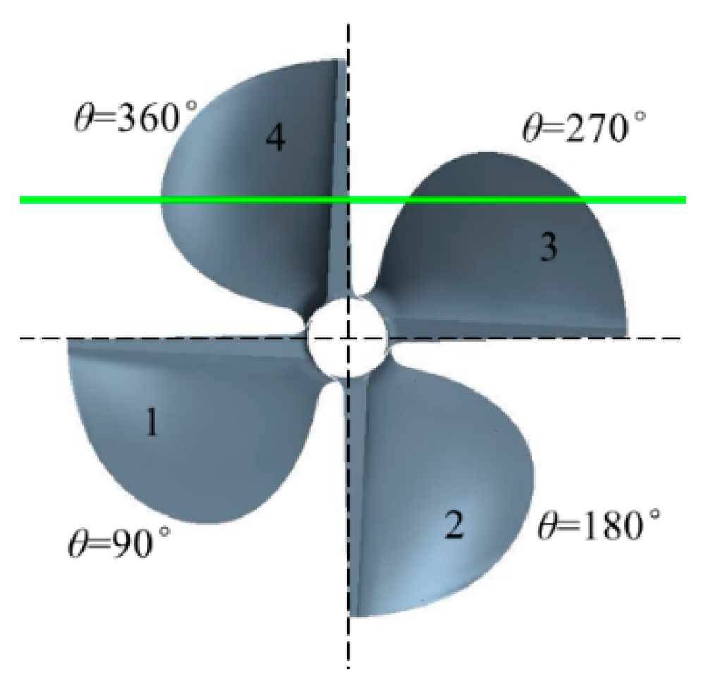
For a more concise description, the blades at different phase are numbered, as shown in Figure 14. Green line indicates the free surface at It = 0.75. θ represents the phase angle.
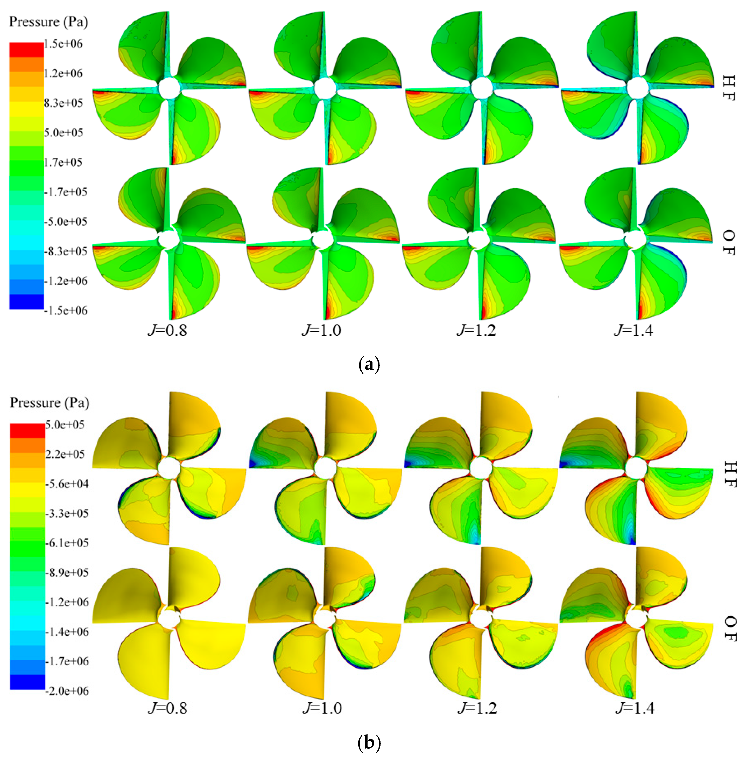
Figure 15 shows the pressure distribution on the surfaces of blades. As shown in Figure 15a, the pressure distribution of No. 2 and No. 3 Blades in the oblique flow at different advance ratios are similar to the horizontal flow cases at the corresponding advance ratios. Meanwhile, the pressure distribution of No. 1 and No. 4 Blades in oblique flow are very different from the results in the horizontal flow. At J = 0.8 in oblique flow, the pressure distribution of No. 1 Blade is similar to the other three blades so that the forces/moments acting on the propeller are more uniform. At high advance ratios, J = 1.2 and 1.4, the pressure distribution of No. 1 Blade in oblique flow is very different from the results in the horizontal flow. This is mainly because that the inflow is blocked by the larger air cavity attached to the suction surface of No. 2 Blade. Generally, the air cavities in oblique flow are always larger than those in horizontal flow so that the higher pressure occurs on the suction side. This can be confirmed in Figure 15b. Since SPP-1 is fully vented at J = 0.8 in oblique flow, the pressure distribution of all the blades is almost the same. However, as the advance ratio increases, the pressure distribution on the suction sides is increasingly uneven. As presented in Figure 15b, the volume of air cavities attaching to the suction sides decreases gradually in the progress of the blades entering and exiting water, so that the area of low pressure on the suction surface of No. 2 Blade is larger than that on No. 1 Blade at J = 1.4. However, the area of the low pressure in the oblique flow is less than that in the horizontal flow.
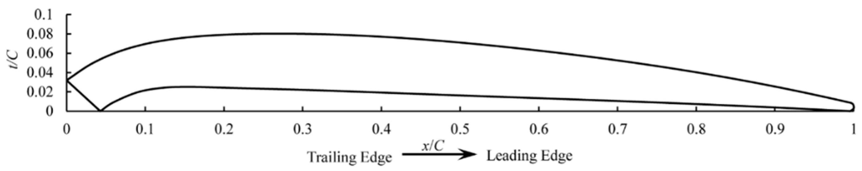
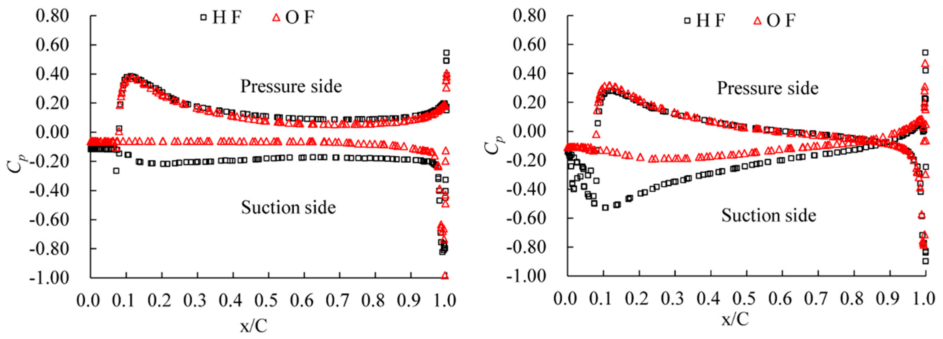
Figure 16 depicts the blade section of SPP-1. Figure 17 shows the pressure distribution of the blade section at 0.7 R of No. 2 Blade in oblique flow (OF) and horizontal flow (HF). As shown in the figure, there is not much difference between the pressure distribution on the pressure sides at J = 1.0 and 1.4 in both conditions. Meanwhile, the pressure on the suction sides increases in oblique flow, which is caused by the air cavity attaching to the blade back. At J = 1.0, the pressure on suction sides in oblique flow remains constant substantially along the whole chord and is always larger than the results in horizontal flow. This indicates that this section is fully vented in oblique flow. At J = 1.4, the pressure in oblique flow is much larger than another case near the trailing edge. Meanwhile, both results are almost the same near the leading edge. It shows that this section is vented partially in oblique flow.
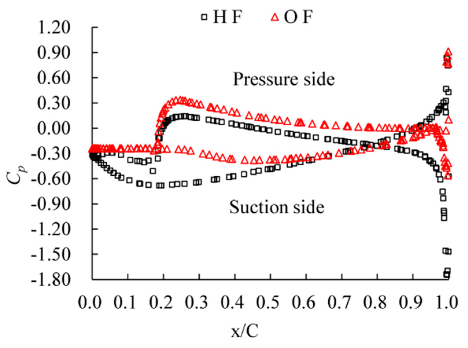
In oblique flow, the volume of the air cavity is much larger than that in horizontal flow. The larger air cavity blocks the inflow and makes the inflow slower, resulting in higher pressure on the pressure side. This can be confirmed in Figure 18, where the pressure on the pressure side at 0.4 R of No. 1 Blade is larger than that in the horizontal case. The pressure (red line) on the suction side in oblique flow is much larger than the results in the horizontal case (black line) at 0.2 < x/C < 0.5 approximately. It illustrates that the air cavity covers this region. The pressure is almost the same at about 0.5 < x/C < 1.0 in both cases, indicating that this region is wetted. The pressure distribution shows that this section is partially vented. The trailing edge is at 0 < x/C < 0.2.
4.4. Wake Field
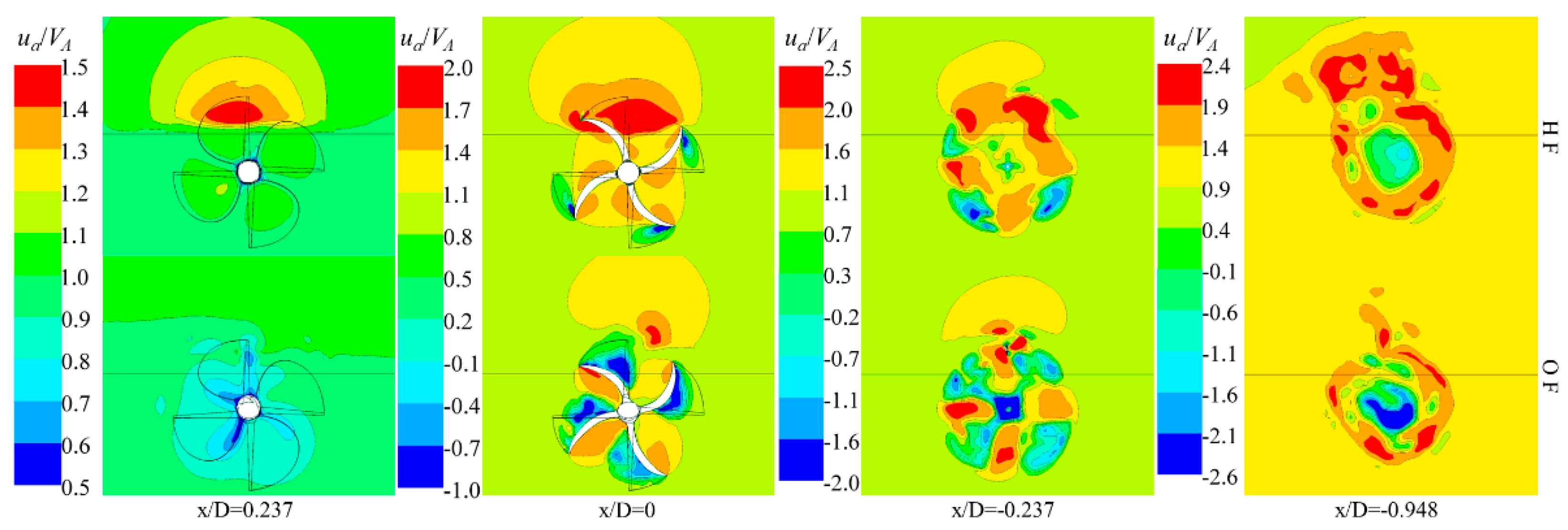
The velocity in the flow field is dimensionless by dividing by the advance speed. The axial velocity contour and the cross-flow vector at J = 1.0 are shown in Figure 19 and Figure 20, respectively. x/D represents the position of plane distance from the propeller disk. The black solid line indicates the free surface. The positive value of the axial velocity indicates that the direction is outwardly perpendicular to the page, and the negative value is the opposite.
Since the inflow is blocked by the air cavities attached to the suction side, the dimensionless axial velocity, ua/VA, is significantly reduced in the oblique flow in front of the propeller disk at x/D = 0.237, as presented in Figure 19. Simultaneously, due to the uplift of the free surface, the influence of the rotation of the propeller on the air is weakened significantly, and the high-speed region above the free surface disappears. At the propeller disk, x/D = 0, the ventilation region on the suction side in the oblique flow is larger than that in the horizontal flow. At x/D = −0.237, it is more obvious that the positive and negative speeds alternate in oblique flow. In the oblique flow, more air is attached to the hub of the propeller, so that the pressure is lower than the results in the horizontal case.
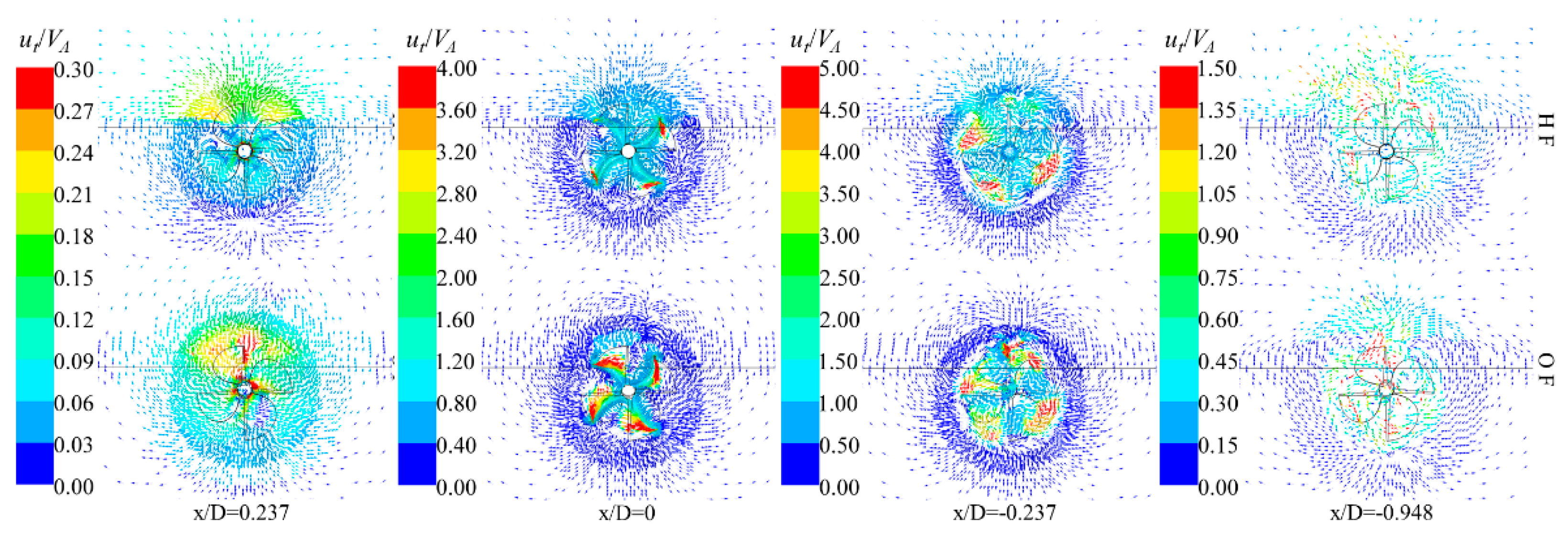
Figure 20 depicts the cross-flow vector. The dimensionless transverse velocity, ut/VA, upstream in the oblique flow is higher than that in the horizontal flow, especially near the shaft. At the propeller disk, there is a larger area of the high-speed region (red region), which is caused by the air along with the propeller. Since the free surface is uplifted by the air cavities, the velocity above the free surface is relatively low at x/D = −0.237 in the oblique flow.
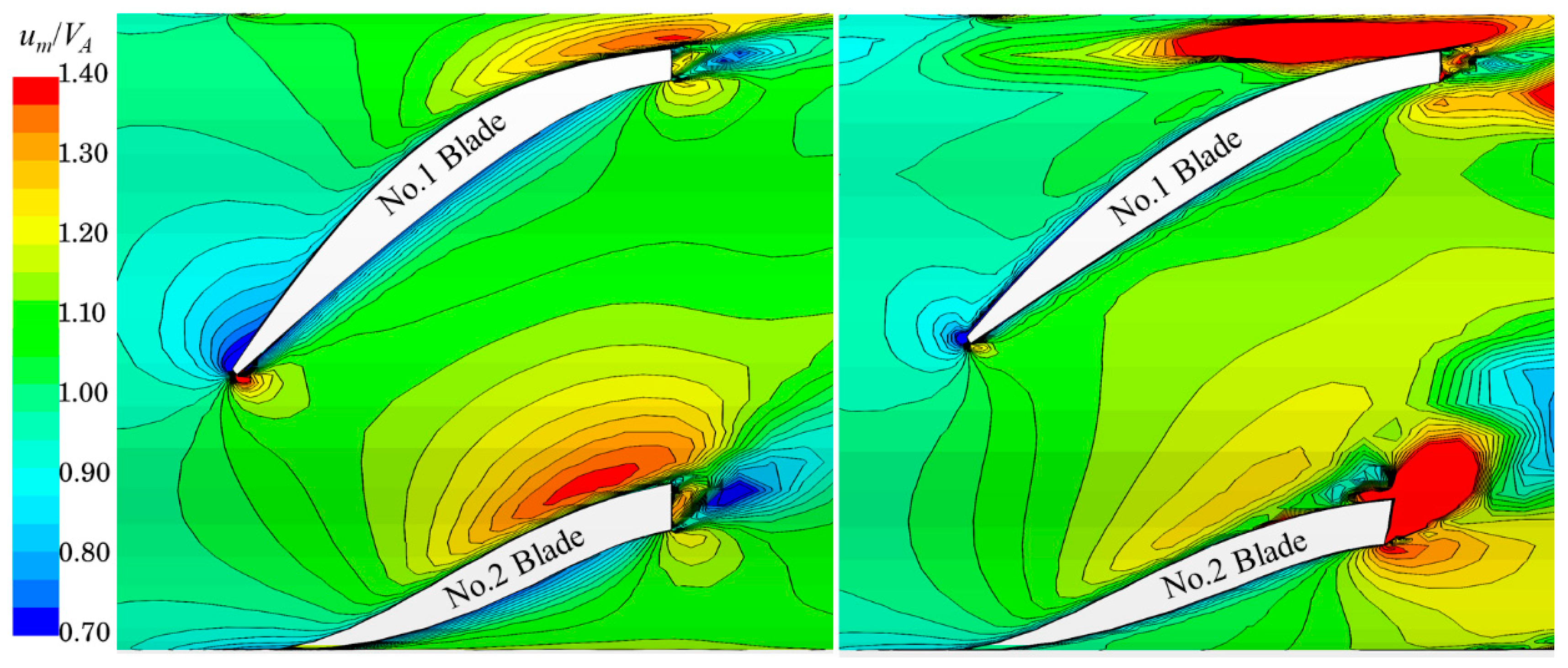
Figure 21 shows the dimensionless velocity magnitude contour at 0.4 R and J = 1.4 between the No. 1 Blade and No. 2 Blade. The dimensionless velocity magnitude in oblique flow is dramatically lower than that in the horizontal flow. In the oblique flow, the trailing edge of No. 2 Blade is vented so that the velocity is much higher than the results in the horizontal case. However, compared with the results in horizontal flow, the velocity near the suction side of No. 2 Blade is much lower in the oblique flow, especially near the trailing edge. This is mainly because the inflow in front of the propeller disk is blocked by the air cavity attached to the suction side of No. 2 Blade. The No. 1 Blade pierces the inflow at a lower speed, which results in the higher pressure.
5. Conclusions
In the present study, the appropriate numerical schemes are explored to predict the open water performance of the standard model PSP-841B by using commercial code Star-CCM+. The same numerical schemes are employed to simulate the hydrodynamic performance of SPP-1 in oblique flow and to analyze the free surface, hydrodynamic performance, pressure distribution and wake field of SPP-1. As a result of the present work, the following conclusions can be drawn:
Compared with the results in horizontal flow, the volume of air cavity attached to the suction sides increases obviously in oblique flow. The obvious uplift of the free surface is equivalent to the increase of the immersion of the propeller. The incensement of ventilation volume strengthens the blockage effect on the inflow, which leads to the variety of the pressure distribution of the blades. At low advance ratios, the blockage effect is more significant and the inflow velocity is lower than the results in the horizontal case. With the advance ratios increasing, the blockage effect tends to be weaker gradually. The relative uplift of free surface leads to a more uniform pressure distribution on the different blades, and the larger air cavity makes the pressure on the blade below the free surface larger than that in the horizontal condition. The forces and moments in oblique flow are much less than the results in the horizontal case in lateral and vertical directions. At high advance ratios, the forces and moments increase rapidly in the oblique flow. Compared with the results in horizontal flow, the thrust and torque increase slightly in the oblique case. In oblique flow, the transition zone is postponed since the volume of air cavity increases dramatically.
The present study provides a reference for the numerical analysis of surface piercing propellers, but there are still many shortcomings such as the lack of study on the hydrodynamic performance at low advance speed. Unlike the conventional propeller, there is a transition zone in the full advance ratios, where the vented mode of the blades is unknown. So, it is necessary to study the flow mechanism of flow field in the transition zone. In addition, the higher turbulence models, for example, scale adaptive simulation (SAS) [24], large eddy simulation (LES) and detached eddy simulation (DES), should be used in future work.
Author Contributions
Z.R. performed the numerical simulations; L.H. and P.J. completed the geometric model, mesh generation and analyzed the post-processing; Z.R. wrote the paper.
Funding
This project is supported by the National Natural Science Foundation of China (Grant No. 51779261).
Conflicts of Interest
The authors declare no conflict of interest. The founding sponsors had no role in the design of the study; in the collection, analyses, or interpretation of data; in the writing of the manuscript, and in the decision to publish the results.
References
- Ferrando, M. Surface piercing propellers: state of the art. Ocean. Eng. Int. 1997, 1, 40–49. [Google Scholar]
- Ding, E.B.; Tang, D.H.; Zhou, W.X. Research review on the semi-submerged propellers. J. Ship Mech. 2002, 6, 75–84. [Google Scholar]
- Hadler, J.B.; Hecker, R. Performance of partially submerged propellers. In Proceedings of the 7th ONR Symposium on Naval Hydrodynamics, Rome, Italy, 25–30 August 1968; pp. 1449–1496. [Google Scholar]
- Misra, S.C.; Gokarn, R.P.; Sha, O.P.; Suryanarayana, C.; Suresh, R.V. Development of a four-bladed surface piercing propellers Series…# 169. Nav. Eng. J. 2012, 124, 111–141. [Google Scholar]
- Ferrando, M.; Panarello, A.; Scamardella, A.; Viviani, M. Model tests and full scale operation with surface piercing propellers. In Proceedings of the Institute of Marine Engineering, Science and Technology. Part B, Journal of Marine Design and Operations; Institute of Marine Engineering, Science and Technology: London, UK, 2003; Volume 3, pp. 21–31. [Google Scholar]
- Chudley, J.; Grieve, D.; Dyson, P.K. Determination of transient loads on surface piercing propellers. R. Inst. Nav. Archit. 2002, 125–141. [Google Scholar]
- Ding, E.B. Study on Test and Design Method of Partially Submerged Propeller. Master’s Thesis, Chinese Ship Scientific Research Center, Wuxi, China, 2002. [Google Scholar]
- Xia, X.; Li, S.C.; Li, H.M. Analysis on surface piercing propellers induced vertical forces. Chin. J. Ship Res. 2006, 1, 68–70. [Google Scholar]
- Furuya, O. A performance-prediction theory for partially submerged ventilated propellers. J. Fluid Mech. 1985, 151, 311–335. [Google Scholar] [CrossRef] [Green Version]
- Young, Y.L.; Kinnas, S.A. Performance prediction of surface-piercing propellers. J. Ship Res. 2004, 48, 288–304. [Google Scholar]
- Young, Y.L. Numerical Modeling of Supercavitating and Surface Piercing Propellers. Ph.D. Thesis, The University of Texas, Austin, TX, USA, 2002. [Google Scholar]
- Young, Y.L.; Savander, B.R. Numerical analysis of large-scale surface piercing propellers. Ocean Eng. 2011, 38, 1368–1381. [Google Scholar] [CrossRef]
- Yari, E.; Ghassemi, H. Hydrodynamic analysis of the surface-piercing propeller in unsteady open water condition using boundary element method. Int. J. Nav. Archit. Ocean Eng. 2016, 8, 22–37. [Google Scholar] [CrossRef] [Green Version]
- Ghassemi, H.; Shademani, R.; Ardeshir, A. Hydrodynamic characteristics of the surface-piercing propeller for the planing craft. J. Mar. Sci. Appl. 2009, 8, 267–274. [Google Scholar] [CrossRef]
- Caponnetto, M. RANSE simulations of surface piercing propellers. In Proceedings of the 6th Numerical Towing Tank Symposium, Rome, Italy, 29 September–1 October 2003. [Google Scholar] [CrossRef]
- Alimirzazadeh, S.; Roshan, S.Z.; Seif, M.S. Unsteady RANS simulation of a surface piercing propellers in oblique flow. Appl. Ocean Res. 2016, 56, 79–91. [Google Scholar] [CrossRef]
- Yari, E.; Ghassemi, H. Numerical analysis of surface piercing propellers in unsteady conditions and cupped effect on ventilation pattern of blade cross-section. J. Mar. Sci. Technol. 2016, 21, 501–516. [Google Scholar] [CrossRef]
- Himei, K. Numerical analysis of unsteady open water characteristics of surface piercing propellers. In Proceedings of the Third International Symposium on Marine Propulsors SMP, Launceston, Australia, 5–8 May 2013; Volume 13, pp. 292–297. [Google Scholar]
- Shi, Y. Numerical Study of the Hydrodynamic Performance of Surface Piercing Propellers. Master’s Thesis, Zhejiang University, Hangzhou, China, 2014. [Google Scholar]
- Yang, D.; Ren, Z.; Guo, Z.; Gao, Z. Numerical analysis on the hydrodynamic performance of an artificially ventilated surface piercing propeller. Water 2018, 10, 1499. [Google Scholar] [CrossRef]
- Olofsson, N. Force and Flow Characteristics of a Partially Submerged Propeller. Ph.D. Thesis, Chalmers University of Technology, Goteborg, Sweden, 1996. [Google Scholar]
- CD-Adapco Group. STAR-CCM+ User Guide Version 9.06; CD-adapco Group: Melville, NY, USA, 2014. [Google Scholar]
- Blocken, B.; Gualtieri, C. Ten iterative steps for model development and evaluation applied to Computational Fluid Dynamics for Environmental Fluid Mechanics. Environ. Model. Softw. 2012, 33, 1–22. [Google Scholar] [CrossRef]
- Rogowski, K.; Hansen, M.; Maroński, R.; Lichota, P. Scale adaptive simulation model for the darrieus wind turbine. J. Phys. Conf. Ser. Iop Publ. 2016, 753, 022050. [Google Scholar] [CrossRef]
Figure 1.
Three-dimensional view of modeling and actual propellers. (a) The 3D view of PSP-841B—left is the actual propeller and right is the 3D model; (b) the 3D view of SPP-1—left is the actual propeller and right is the 3D model.
Figure 1.
Three-dimensional view of modeling and actual propellers. (a) The 3D view of PSP-841B—left is the actual propeller and right is the 3D model; (b) the 3D view of SPP-1—left is the actual propeller and right is the 3D model.

Figure 2.
Immersion of surface piercing propellers.

Figure 3.
Global and local coordinates, forces and moments along and about different axis.

Figure 4.
Computational domain and boundary conditions.

Figure 5.
Local mesh of SPP-1 and interface.

Figure 6.
Contour of y+ on SPP-1 key blade.

Figure 7.
Comparison between the predicted and experimental data of PSP-841B.

Figure 8.
Free surface of SPP-1 in horizontal and oblique flow. (a) The free surface of SPP-1 in horizontal (left) and oblique (right) flow at J = 0.8; (b) the free surface of SPP-1 in horizontal (left) and oblique (right) flow at J = 1.4.
Figure 8.
Free surface of SPP-1 in horizontal and oblique flow. (a) The free surface of SPP-1 in horizontal (left) and oblique (right) flow at J = 0.8; (b) the free surface of SPP-1 in horizontal (left) and oblique (right) flow at J = 1.4.

Figure 9.
Gas-liquid distribution on the xz plane at J = 0.8.

Figure 10.
Free surface on the different cutting planes.

Figure 11.
Air cavity and free surface at x = 0 mm.

Figure 12.
Open water performance of SPP-1 in horizontal flow (HF) and oblique flow (OF).

Figure 13.
Forces/moments acting on SPP-1 in horizontal (HF) and oblique flow (OF). (a) Forces acting on SPP-1 in horizontal (HF) and oblique flow (OF); (b) moments acting on SPP-1 in horizontal (HF) and oblique flow (OF).
Figure 13.
Forces/moments acting on SPP-1 in horizontal (HF) and oblique flow (OF). (a) Forces acting on SPP-1 in horizontal (HF) and oblique flow (OF); (b) moments acting on SPP-1 in horizontal (HF) and oblique flow (OF).

Figure 14.
Phase angle and number of different blades.

Figure 15.
Pressure distribution on blade surfaces. (a) The pressure distribution on pressure side; (b) the pressure distribution on suction side.
Figure 15.
Pressure distribution on blade surfaces. (a) The pressure distribution on pressure side; (b) the pressure distribution on suction side.

Figure 16.
Blade section.

Figure 17.
Pressure distribution at 0.7 R of No. 2 Blade (left: J = 1.0; right: J = 1.4).

Figure 18.
Pressure distribution at 0.4 R of No. 1 Blade at J = 1.4.

Figure 19.
Comparison of axial velocity contours at different cutting planes.

Figure 20.
Comparison of cross-flow vector at different cutting planes.

Figure 21.
Comparison of dimensionless velocity contours near Blade No. 1 at 0.4 R and J = 1.4 (left: horizontal flow; right: oblique flow).
Figure 21.
Comparison of dimensionless velocity contours near Blade No. 1 at 0.4 R and J = 1.4 (left: horizontal flow; right: oblique flow).


Table 1.
Main parameters of PSP-841B and SPP-1.
| Parameters | PSP-841B | SPP-1 |
|---|---|---|
| D (mm) | 250 | 633 |
| H/D | 0.34 | 0.15 |
| P/D at 0.7r | 1.24 | 1.60 |
| EAR | 0.58 | 0.83 |
| Blades Number | 4 | 4 |
| Rotation Direction | right | left |
Table 2.
Mesh independency.
| Grid Number (Million) | Kt | Error | 10 Kq | Error |
|---|---|---|---|---|
| EFD | 0.0511 | 0.1099 | ||
| 1.4 | 0.0572 | 12.1% | 0.1236 | 12.4% |
| 2.6 | 0.0560 | 9.5% | 0.1197 | 9.0% |
| 3.8 | 0.0551 | 7.8% | 0.1167 | 6.1% |
| 5.0 | 0.0546 | 6.9% | 0.1151 | 4.7% |
© 2019 by the authors. Licensee MDPI, Basel, Switzerland. This article is an open access article distributed under the terms and conditions of the Creative Commons Attribution (CC BY) license (http://creativecommons.org/licenses/by/4.0/).
Share and Cite
MDPI and ACS Style
Ren, Z.; Hua, L.; Ji, P. Numerical Analysis on Hydrodynamic Characteristics of Surface Piercing Propellers in Oblique Flow. Water 2019, 11, 2015. https://doi.org/10.3390/w11102015
AMA Style
Ren Z, Hua L, Ji P. Numerical Analysis on Hydrodynamic Characteristics of Surface Piercing Propellers in Oblique Flow. Water. 2019; 11(10):2015. https://doi.org/10.3390/w11102015
Chicago/Turabian StyleRen, Zhen, Lin Hua, and Penghui Ji. 2019. "Numerical Analysis on Hydrodynamic Characteristics of Surface Piercing Propellers in Oblique Flow" Water 11, no. 10: 2015. https://doi.org/10.3390/w11102015
Note that from the first issue of 2016, this journal uses article numbers instead of page numbers. See further details here.