Hydraulic Capacity and Efficiency of a Low-Speed Nonpressurized Coil Pump


Department of Hydraulic and Sanitary Engineering, Poznan University of Life Sciences, Piątkowska 94A, 60-649 Poznań, Poland
*
Author to whom correspondence should be addressed.
Water 2019, 11(8), 1659; https://doi.org/10.3390/w11081659
Submission received: 4 July 2019
/
Revised: 2 August 2019
/
Accepted: 8 August 2019
/
Published: 10 August 2019
(This article belongs to the Special Issue Smart Hydraulics in Wastewater Transport)
Abstract
:The paper presents the results of an investigation on hydraulics of a low-speed coil pump for transport of liquids. One of the pump’s advantages is its wide range of potential inclination angles for its rotating shaft, from the horizontal to an almost vertical position. A simplified hydraulic model was developed based on kinematic and geometrical considerations to determine the pump capacity. The model was verified under laboratory conditions using a low-speed coil pump composed of transparent PVC tube (15 mm outer diameter) wound around a cylindrical drum (104 mm external diameter; 550 mm long). Laboratory tests were performed for three angles of inclination of the axis of rotation (20°, 40°, and 60°) and four rotational speeds (10, 20, 30, and 40 rpm). The results of the tests showed satisfactory agreement with the hydraulic model predictions. Energetic efficiency was estimated on the base of electric power measurements and difference of water levels in the two arms of rotating transparent torus, partly filled with water. The hydraulic efficiency of the coil pump is increasing with decreasing rotational speed.
1. Introduction
The Archimedean screw is one of the oldest devices for water raising. It was described, although not necessarily invented by Archimedes [1]. The screw rotates inside a tube or trough, pushing portions of water ahead. The screw axis is inclined and its lower end picks up water from the source, whereas the upper end discharges into an irrigation ditch. The optimum angle of inclination, usually in the range of 30° to 40°, depends on the pitch and the diameter of the internal helix. The main disadvantage of the Archimedean screw is water loss through the slots between the screw and its casing [2]. Its hydraulic efficiency may reach up to 80%, including when used as a small hydro-power turbine [3,4,5]. In the latter case, the angle of inclination ranges between 20° and 30° to gain maximum torque.
A similar principle is applied in spiral pumps. The spiral pump, invented most probably by Wirtz (1746), is composed of a tube wound in the form of an Archimedean spiral. Its outer, broader end picks up water from the source during the rotation of the shaft. Its inner end, located at the axis of rotation, discharges liquid into a channel or pipeline. While it is easy to construct, the critical part of the spiral pump is its rotary fitting (swivel). It provides a relatively watertight seal to prevent water and pressure losses. Unfortunately, it often leaks and generates friction and losses of energy. An overall efficiency of up to 75% can be achieved for a well-designed spiral pump [6]. Apart from liquid lifting, the spiral pump may be used to remove floating pollutants from the surface of the sea [7,8]. Structures based on the idea of a spiral pump may also be applied in wastewater treatment facilities or in heat exchangers and chemical reactors thanks to efficient mixing by secondary currents [5,9,10,11,12]. A coil pump is based on the same principle as the spiral pump, but the tube is wound around either a conical drum or a cylindrical drum, as a result creating a helix. The principle is that water is picked up by the submerged end of the tube each time it dips below the surface; however, due to the dynamic effects, the entrapped air is pressurized. The maximum pressure builds up at the outlet, while the liquid plugs rotate in a manner that suggests that they are creating a form of multiple (cascading) manometer. This type of pump, although in a nonpressurized version, was originally described by the Roman architect and engineer Vitruvius in the first century B.C. It has attracted considerable renewed interest recently, with research projects concerning this design conducted at several universities. Today the coil pump is recommended for use in stream (river current) powered irrigation pumps [13,14,15]. The coil pump powered by the water flow is sometimes called a sling pump. It can also be driven using other nonconventional energy sources (pedal, animal, wind or solar) or even manually. Due to the presence of air plugs, water or wastewater is partly aerated; therefore the pump can also be used for wastewater treatment [16,17], particularly for wastewater pretreated mechanically in septic tanks, e.g., in a small diameter sewerage system [18].
The majority of studies on coil pumps were performed using designs with a horizontal axis of the cylindrical drum. We have found only three studies on the role of inclination of the axis of rotation [19,20,21]. Inclining the axis of rotation allows elimination of the rotating seal, since the coiled tube and the inclined force main are now joined to form one component. This also means that the force main may be used as the drive shaft, enabling the pump to be driven from dry land as an alternative to the drum being driven by the stream power. The inclined coil pump is therefore more versatile in terms of the source of power.
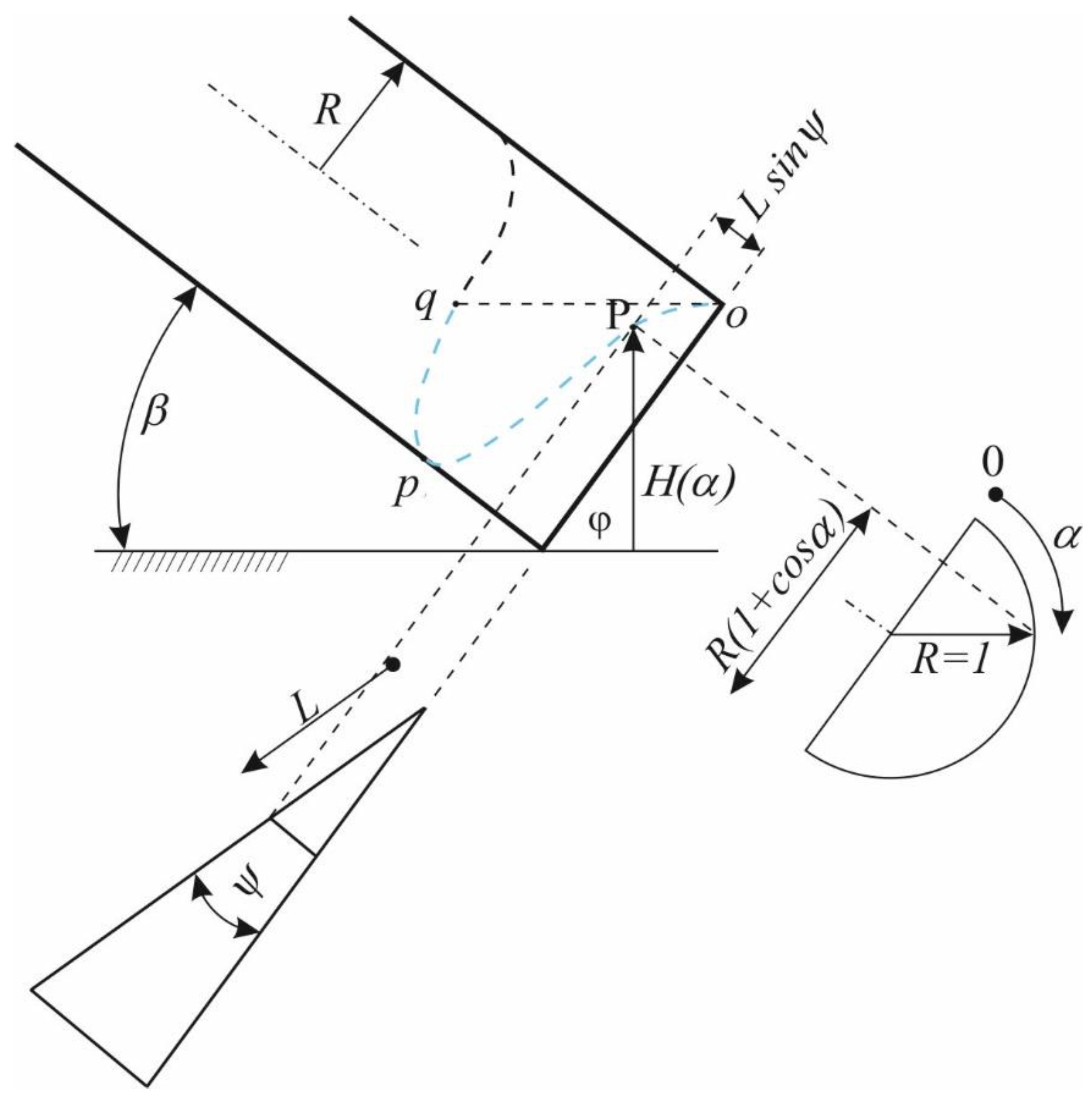
Koetsier and Blauwendraat [22] provided a detailed review of historical attempts to formulate a theory of the Archimedean screw pump. Among the contributors they listed such famous names as Archimedes himself, L. da Vinci, G. Cardano, G. Galilei, D. Bernoulli, and J. Weisbach. Especially interesting and useful is a formula derived by D. Bernoulli, using which allows to calculate the height above the horizontal plane H(α) of a point P on the cylindrical helix (Figure 1) as the function of α, the angle of rotation during the generation of the helix [22], in the form of
where ψ is the inclination of the cylindrical helix to the pump baseline and β is the angle of inclination of the axis of rotation to the horizontal.
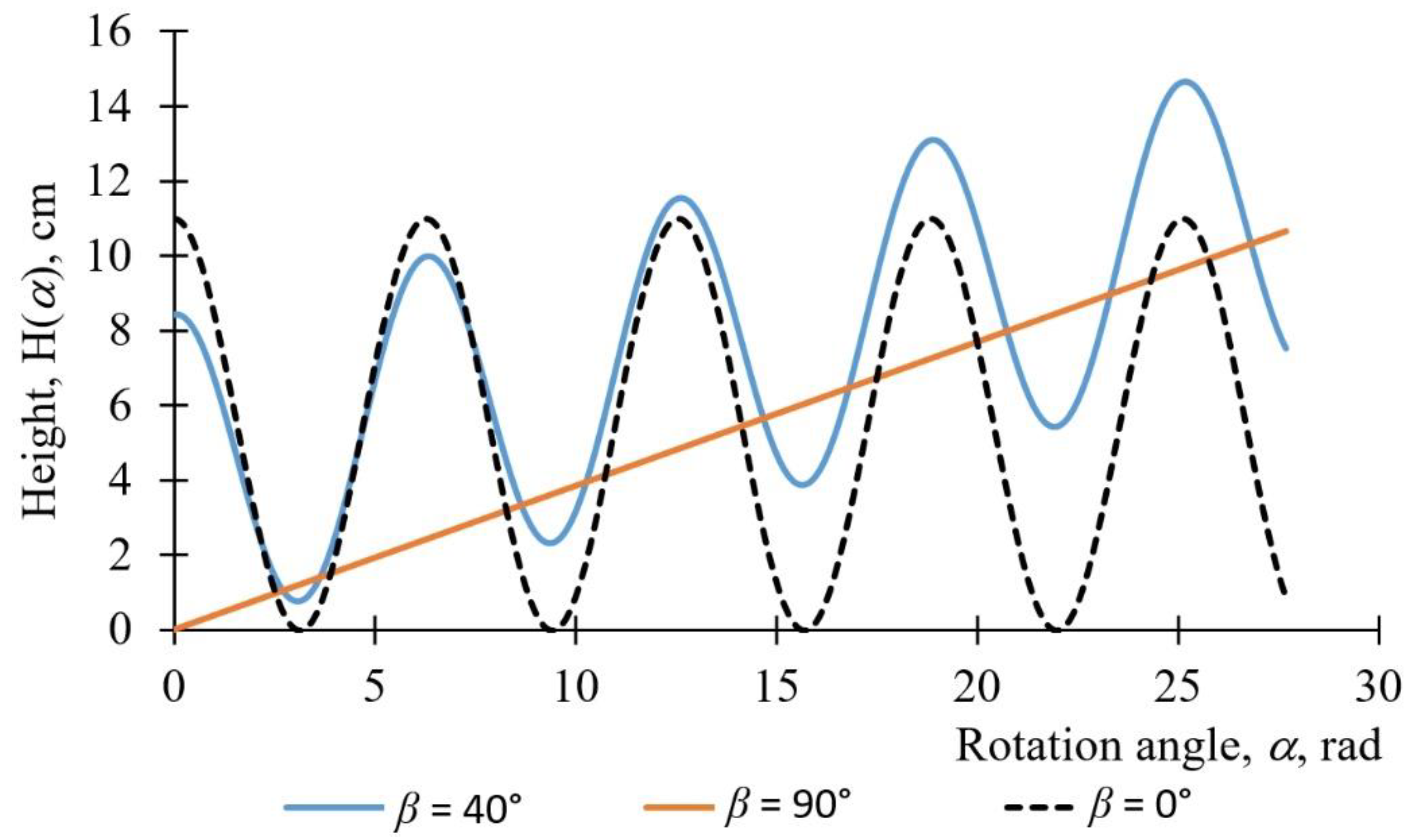
A diagram of Equation (1) for the selected inclination angles β at the helix inclination angle ψ = 3° (typical for closely wound tube) is shown in Figure 2.
In the interval 0 < α < π, corresponding to the first section of the cylindrical helix, Equation (1) has no extrema when ψ > 90 − β; the helix is then an ascending curve and water does not enter the tube. The same result was obtained by Galilei, who deduced it somewhat differently. However, when ψ < 90 − β, Equation (1) has two extrema: there is a maximum corresponding to point o and a minimum corresponding to point p. Bernoulli remarked that in this case the volume of water in one pocket is determined by the section opq of the helix (Figure 1), with q being on the same level as o. He stated that the length of this pocket cannot be determined algebraically, but may be approximated in every specific case.
The maximum value of H(α), corresponding to point o, can be found from the first derivative of the function expressed by Equation (1), equaled to zero:
hence
A theoretical explanation and description for the formation of gas and liquid plugs in the classical, pressurized coil pump was provided by Mortimer and Annable [15]. The theory was successfully confirmed by those researchers as well as Kassab et al. [23]. Mortimer [16] thoroughly investigated the coil pump in two variants: as a lift and as a suction (single and double) pump.
Kassab et al. [24] stated that the application of a two- or three-layer coil pump improves its performance (head and discharge), mainly due to the upper tube layer. Increasing the tube and drum diameter also led to improved coil pump performance. Rorres [25] found the optimal inner radius and pitch that maximize the volume of water lifted in one turn of the Archimedean screw. Optimal parameters’ values were found to be close to those used in a screw described by Vitruvius and with values used in the design of modern Archimedean screw pumps.
This paper presents investigations of a low-speed coil pump in the form of tube wound helically around a cylindrical drum, without any force main on the outlet. Alternatively, the pump can be called a tubular (helical) hydraulic elevator [26]. Such a design eliminates leakage; hence, its volumetric efficiency is theoretically equal to 100%. The rotation speed is so low (≤40 rpm) that the air pressure between the liquid plugs (pockets) is close to the barometric one. The pump only allows the lifting of water over a small height (up to a few meters); therefore, in some ancient structures, the Romans applied several stages of lifting, as in the case of the Augsburg Machine [22]. The theory of the pump work is relatively simple, but, to our best knowledge, it has not been experimentally verified for low-speed coil pumps. Though so old, the coil pump design is continuously being improved and its prospects for innovation and commercialization are promising.
2. Materials and Methods
2.1. Theoretical Considerations
In order to calculate the capacity of a nonpressurized coil pump, the following geometrical analysis was carried out.
The length of a helix curve, created by a polar radius R turning around at an angle α, (Figure 1) can be expressed as
where R is the radius of the cylindrical helix, l is the lead and α is the angle of rotation.
Therefore the length of one coil is equal to
A helix lead is defined as the length of one complete helix turn (coil), measured parallel to the axis of the helix. The length of a lead is equal to the product of its pitch (the lead at the closest winding) and the number of starts. The relative inner volume of one coil of a tube (for α = 2π) with the same circular cross-section depends on the following length ratio.
where V1 is the volume of a circular coil, i.e., torus, (S = 0) of radius R, V1l is the volume of an expanded cylindrical coil of length L1 (l > 0). For l/R < 1 V1l/V1 < 1.013, i.e., the relative volume difference is less than 1.3%.
Assuming the closest tube winding, the length of a cylindrical helix curve is approximately equal to the length of a circular arc, namely,
where c is the chord length and S is the sagitta of one vertical or tilted liquid pocket. The latter is approximately equal to
where ψ is the inclination of the cylindrical helix to the pump baseline; for the closest winding with a pitch at one start
where r is the outer diameter of the coil tube.
To fill a helical pocket with liquid and to carry it upwards the following conditions need to be fulfilled:
- β > 90 − ψ, where the angle unit is deg.
- the tube inlet must be submerged intermittently below the liquid level to create a plug flow.
The chord length of the circular pocket in its lower half (S ≤ R) is equal to
Similarly, the chord length in the upper half (S > R) may be calculated treating the sagitta as a measure of gas content at the coil top.
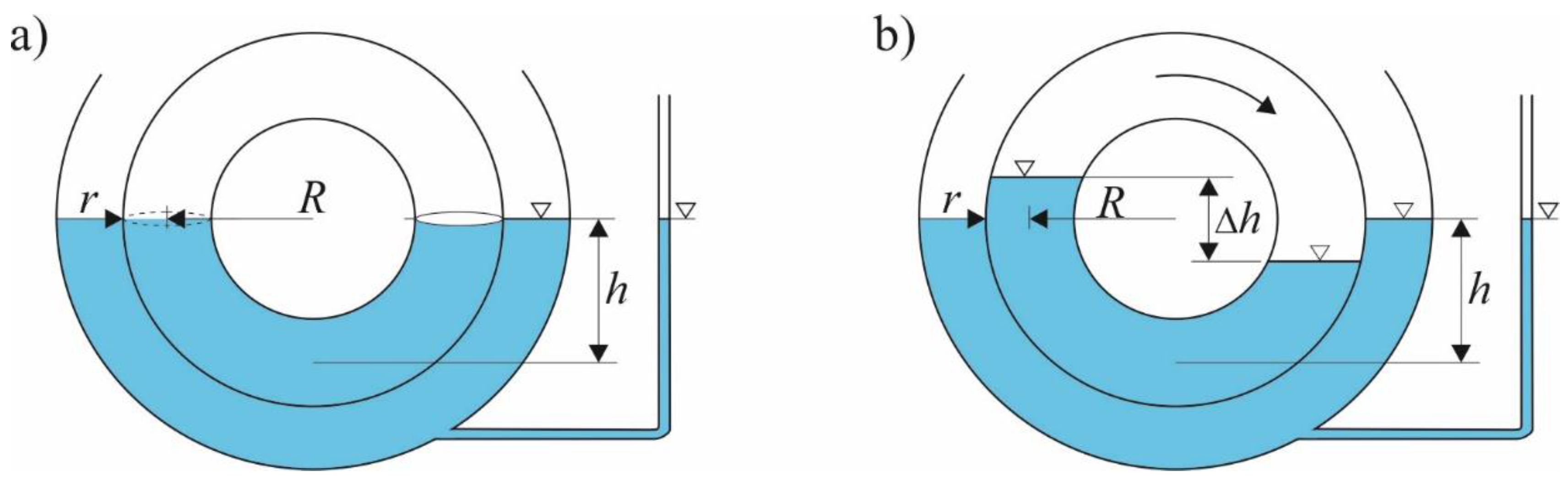
We assume that a single tube fill depth is equal to the submergence depth h (Figure 3), which is possible when the rotational speed is sufficiently low. The liquid volume in one partly filled coil with l/R < 1 and h > 2a can then be calculated as
where a is the inner radius of the tube.
Equation (11) is valid for a < h < 2 R − a.
More generally, using Equation (7), the pump yield can be expressed by
where n is rotational speed, expressed in revolutions per time unit.
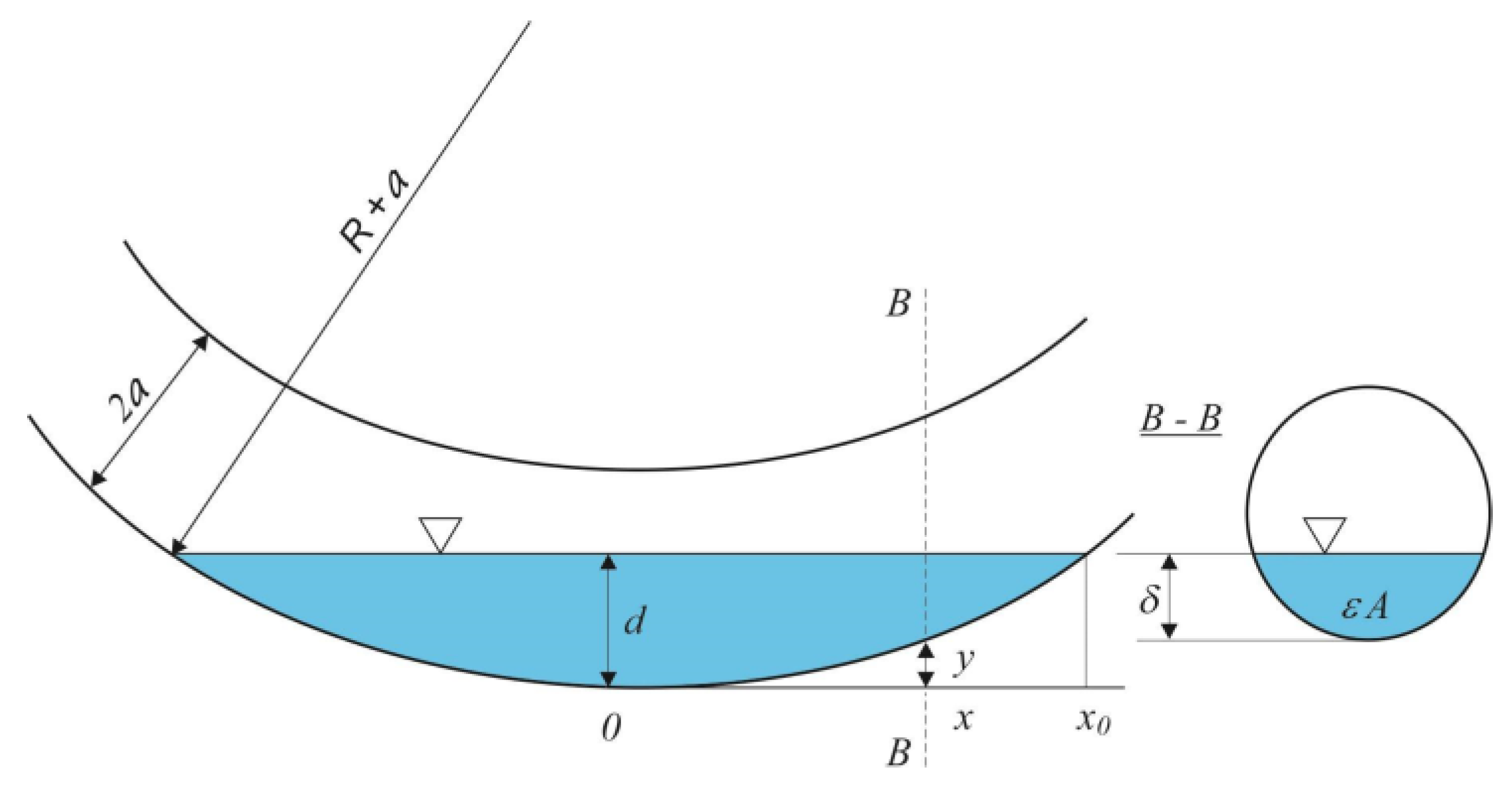
A certain unusual mode of operation for the nonpressurized coil pump is to elevate small portions of liquid, which do not create plugs. The air can flow over the surface of successive liquid portions, because it is not blocked by liquid plugs. For small fillings of the coil tube the following method of liquid pocket volume estimation was applied. For a given cross-section, e.g., B-B in Figure 4, liquid depth in the tube is equal to
in the dimensionless form
The pocket of liquid extends from −x0 to x0, therefore assuming symmetry its volume Vp can be estimated as
where
Function (15) must be integrated numerically.
2.2. Construction of the Studied Helical Coil Pump
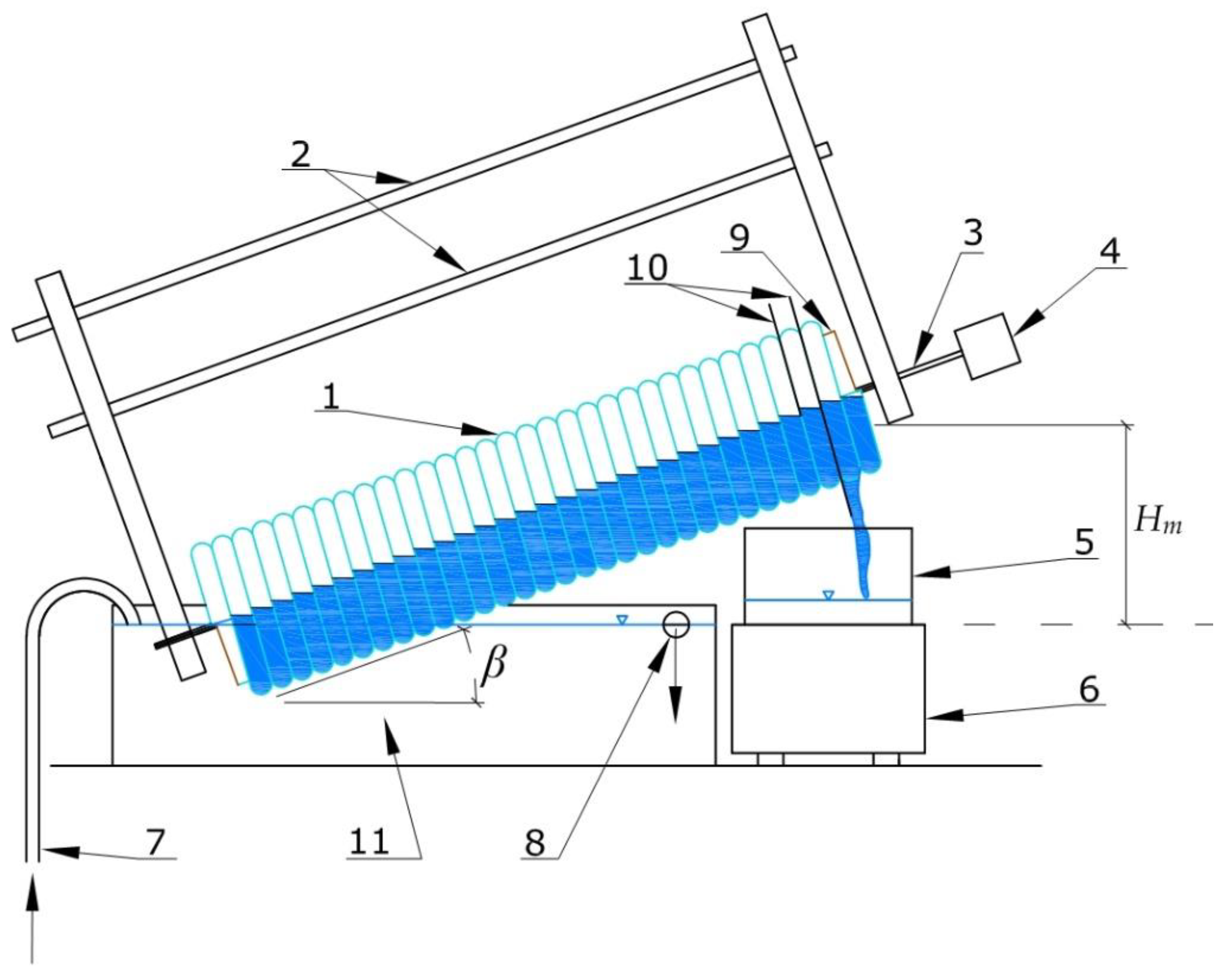
The tested pump (Figure 5) was made of transparent PVC tube of outer/inner diameter 15/12 mm (1), wound around a cylindrical drum made of PVC (9) of external diameter 104 mm and 550 mm long. The number of coils on whole length of drum was 32. The inner tube diameter was verified by a volumetric method—as a result the mean inner tube diameter was determined to be 11.2 mm (a = 5.6 mm) instead of the factory value of 12.0 mm. The coil pump was installed in a tank with a capacity of 6.8 dm3 (10) filled with water to a given level, controlled by the overflow (8). Supply water was pumped by a small centrifugal pump through the inlet (7) to maintain a constant water level. With the line of sight along the ascending drum axis, the sense of tube winding was opposite to the direction of the drum revolutions (called counter-winding) to provide a forward (upward) flow in the tube (1). The rotating drum (3) was driven by the 12VDC motor (4) and the transmission with the reduction ratio of 0.44. When lifting the liquid through the coil-pump, the water level in the following coils, can be observed. The liquid outflowing from the uppermost coil was captured by collar (10) and directed to a container (5). The container, together with the water flowing out of the coil pump, was weighed using the electronic balance (6).
To determine input power and to assess energetic efficiency of the coil pump, input voltage and current were measured using voltmeter and ammeter at the power supply terminals.
2.3. Experiment
The pump capacity was tested at four rotational speeds, i.e., 10, 20, 30, and 40 rpm. The planned submergence depth of the lower part of the drum was provided using a small centrifugal pump and the overflow, through which the surplus liquid was removed. Thus, the inlet submergence was kept at a constant value h = 5.75 cm. During the successive revolutions, the tube took the liquid and air portions and lifted them up. The drum revolutions were maintained until outflow from the upper outlet filled partly the container (5). The collected water mass measurements, using the electronic balance (6), were sent to the computer and recorded with the sampling frequency 2 s.p.s.
The hydraulic model was validated by 12 experiments (see Table 1). The influence of the angle of inclination of the drum on the submergence conditions is shown in Figure 6.
In Figure 6a–c, the coil pump is shown at inclination angles 20°, 40°, and 60°. The angle of inclination of the drum up to a critical value β = 90 − ψ does not affect the pump capacity.
Water level difference Δh in two arms of rotating torus of radius R = 8.8 cm and inner tube diameter a = 6 mm was determined basically for checking the applied head-loss calculation procedure. In experiment the difference was measured from photographs.
A portion of water corresponding to filling half of the first coil was introduced into the initially empty coil pump. To increase the contrast, the water was stained with fluorescein. Then the motor was started at a certain speed and the flow of the liquid portion was observed over successive coils. The liquid flow phenomenon was recorded using a 1080 HD video camera (of a resolution matrix of 1920 × 1080 pixels) at 30 fps. To determine the scale of the image on the surface of the coils, a millimeter scale was applied. The optical axis of the lens was positioned at the liquid level in the coils, and the tangent plane to the curved surface of the coil was perpendicular to the optical axis. This reduced the influence of the curvature of the shaft on the angle of observation and the need to take into account geometrical distortions. Video in mp4 format was processed into pictures (with a resolution of 96 dpi) on which, using the ImageJ software, the number of pixels between the dynamic, lower liquid meniscus, and the static one was measured. The calculated scale factor was 12.45 pixels per 1 mm of the observed object (around the lens axis).
Reading liquid levels was based on the analysis of images obtained from films, always for the fourth and seventh coils. The level reading position was marked on the circumference of the coils. Knowing the number of pixels and the determined image scale, the dynamic and static levels were read and the difference between the two levels was calculated. Reading the levels for specific places on the coils allowed making measurements independent of the influence of imperfections in the winding of the total 32 coils.
3. Results and Discussion
3.1. Capacity
Theoretical analysis using Equation (9) showed that, at the closest tube winding, the angle of inclination of the drum axis to the horizontal can reach its maximum values due to the smallest value of the helix angle ψ (Figure 2). In the tested coil pump, the maximum permissible inclination angle of the drum β = 90 − ψ = 86.8° was provided for the lead l = DN = 15 mm (Figure 6d). At larger β, the liquid flowed down completely from the first (inlet) coil.
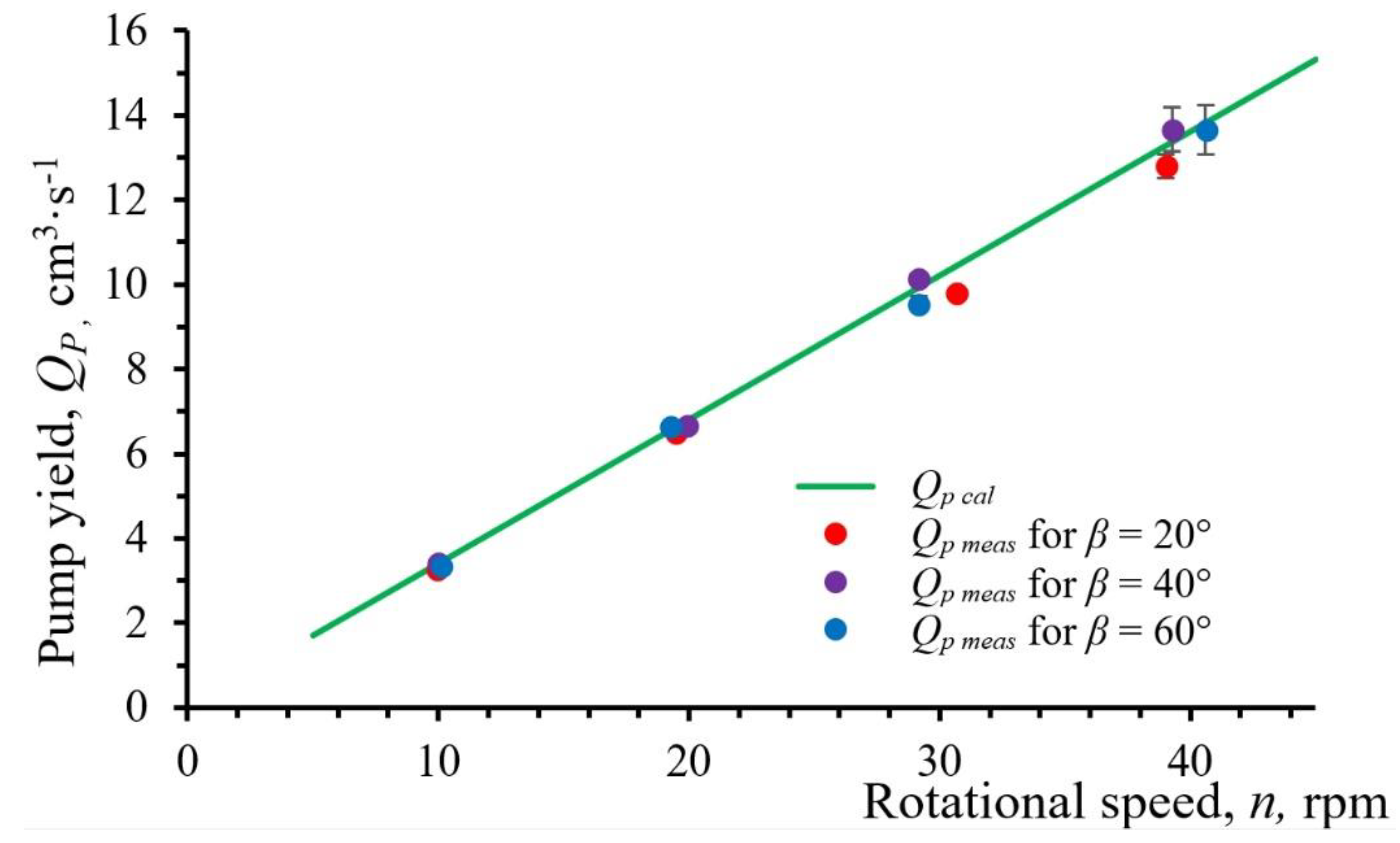
Calculations of the pump capacity were made using Equation (12) for the values given in Table 1. A comparison of calculated and measured values of the coil pump capacity shown in Figure 7 indicates their good agreement. To evaluate the hydraulic model, a coefficient of variation, based on the relative squared error, was calculated according to the following formula [27].
where Xc is the value calculated using Equation (12), Xei is the i-th measured value, Xea is the average measured value, and m is the number of measurements.
Calculated values of the coefficient of variation are given in Table 2. Considering the above mentioned uncertainties, CV (RMSE) < 5% indicates a relatively good agreement between the theory and experiments. In all experiments the differences between the results of experiments and calculations fell within the limits of measurement errors. It can be stated that in the tested range the rotational speed of the drum had no significant effect on the effectiveness of coil filling. Small fluctuations of the submergence depth of the lowest coils may significantly change the volume of lifted water. The observations also confirmed the equality in the levels/volumes of water in successive coils, provided that the submergence of the lowest coil during drum rotation was constant. Indirectly, this is a confirmation for the assumption that the air plugs are not compressed by the liquid plugs. At the same time, this statement is limited only to nonpressurized pumps, i.e., the head Hm depends only on the drum length and its inclination.
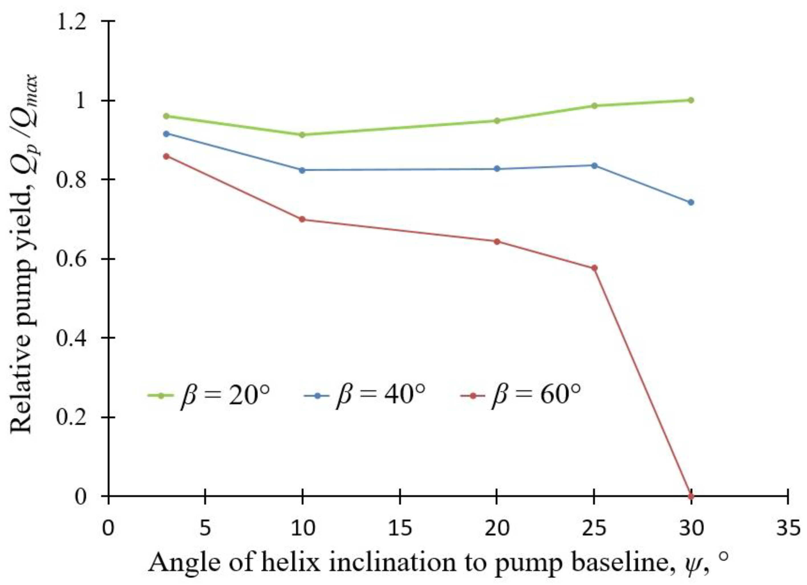
Relative pump yield depends to a differentiated degree on drum and helix inclinations (Figure 8). At relative small helix angles the dependence is rather weak. With increasing helix angles the relative pump yield dramatically decreases for the highest (β = 60°) drum inclination but it may even increase for the smallest (β = 20°) drum inclination to horizontal.
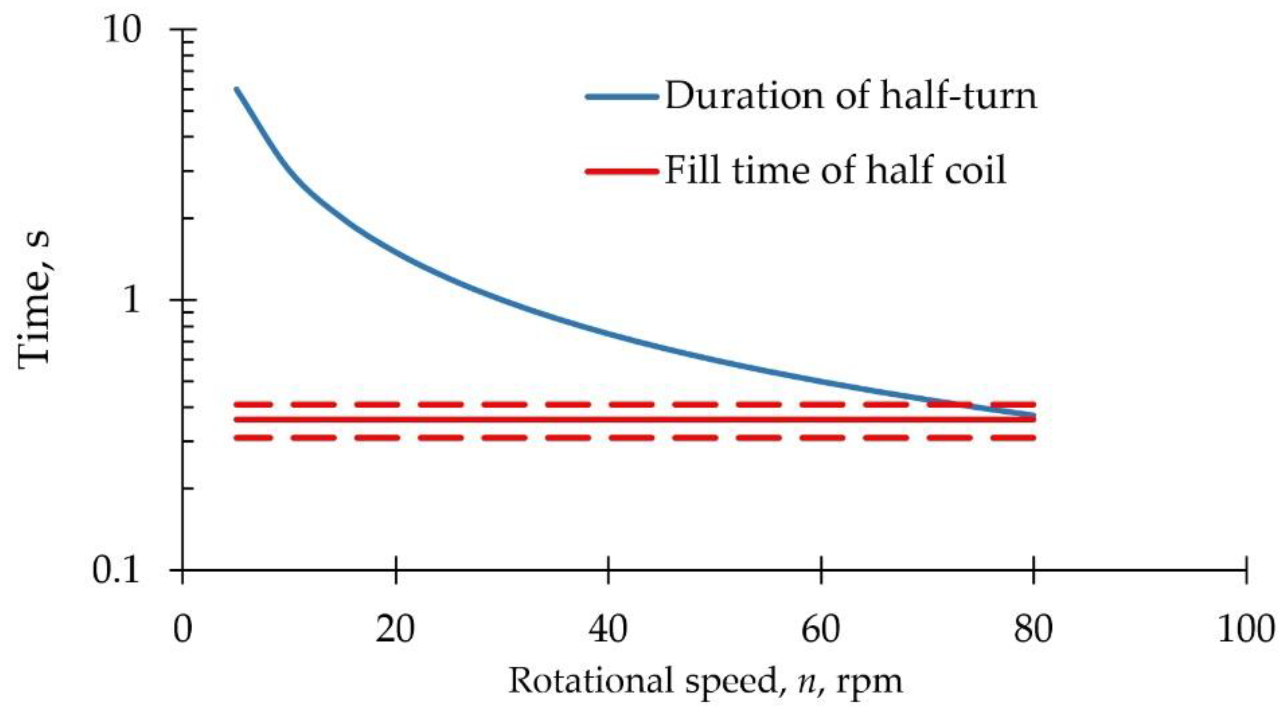
To determine the fill time of coils simple experiments were conducted: one coil of the same tube as in the pump (a = 6 mm), wound around a short piece of pipe of 100 mm in diameter, was rapidly submerged under water and the fill time of the coil was measured. Ten experiments showed the average fill time of 0.72 ± 0.10 s. That value was divided by two to estimate the shorter fill time of a half coil (Figure 9) and to compare it with the duration of a half-turn, during which the tube inlet is submerged. It can be seen that to provide proper filling, the maximum rotational speed should be not greater than 60–70 rpm. A slightly lower limit (50 rpm) is also valid for Archimedean screws; if the screw is rotated much faster, turbulence and sloshing prevent the buckets from being filled and the screw churns the water in the lower pool rather than lifting it [26].
In our case, as can be deduced from Equation (4), the greater the tube lead is, the greater the volume of one coil, but the number of coils along a given drum length is smaller. In the case of the studied helices, their lead l = 0.015 m, i.e., one tube created 32 coils around a drum of 0.5 m in length. It is worth to note that liquid plugs “flow” with a velocity equal to the peripheral speed 2πRn. Flow velocities inside the tubes reached 14–15 cm/s at the rotational speed n = 20 rpm. Such a low linear wastewater velocity should not be harmful to a biofilm on wall surfaces of the tubes, as Hochheimer and Wheaton [28] assessed that velocities < 30 cm/s are acceptable for safe attachment of biofilm on rotating biological contactors.
3.2. Efficiency and Torque
Typically, overall efficiency of a fluid flow process involving a pump is related to the hydraulic, mechanical, and volumetric losses in the pump.
The hydraulic efficiency of a coil pump (excluding the bearing friction) is defined as the power ratio, as follows
where Pl is the power needed to lift water in the gravity field, and Pf is the power needed to surmount fluid friction within the coil pump.
The power needed to lift water by the coil pump can be estimated as
It is worth to noting that Equation (19) is equivalent to equation
where n is rotational speed, rps; N is the number of pockets; and M is the moment that the weight of the water G exerts about the axis of the cylindrical helix, which is expressed in the following form given by Bernoulli [23].
where G is the weight of the water in the whole pocket opq (Figure 1).
The power needed to surmount fluid friction within the coil pump can be estimated as
Assuming that the fluid velocity in the coil tube is equal to the peripheral speed, the former can be expressed as
The shear force in the coil tube can be expressed as
where Lp is length of the liquid pocket, m, and τ is wall shear stress, N/m2.
The shear stress in coil tube can be expressed as
where fc is the friction factor for liquid flow in a coil tube, -.
Numerous publications [29,30,31,32,33] indicate that the friction factors values for a coil tubes are higher than their counterparts in straight pipelines. Therefore, the use of classical equations to calculate the value of friction factors will give underestimated values. Nevertheless, the friction factor for a coil tube is calculated on the basis of the friction factor for a straight pipe. Several equations have been proposed to calculate the friction factor at laminar flow in a coil tube. For example, White [29] proposed the following formula, which was obtained experimentally.
Similarly, Ito [30] proposed the following empirical formula.
where fs (-) is the friction factor for a straight pipe (for laminar flow fs = 64/Re, Re = 2av/ν—Reynolds number, -; ν is kinematic viscosity of the fluid, m2/s; and De = Re(a/R)0.5 is Dean number, -.
On the other hand, Hart et al. [31] developed the following formula.
Other formulae for the friction factor at laminar flow in coil tubes can be found in the review provided by Ghobadi and Muzychka [32] and for transitional and turbulent flows by Fsadni and Whitty [33].
Comparison of values of head losses Δh, calculated by Darcy-Weisbach formula, with relevant experimental data (Figure 10) show acceptable agreement.
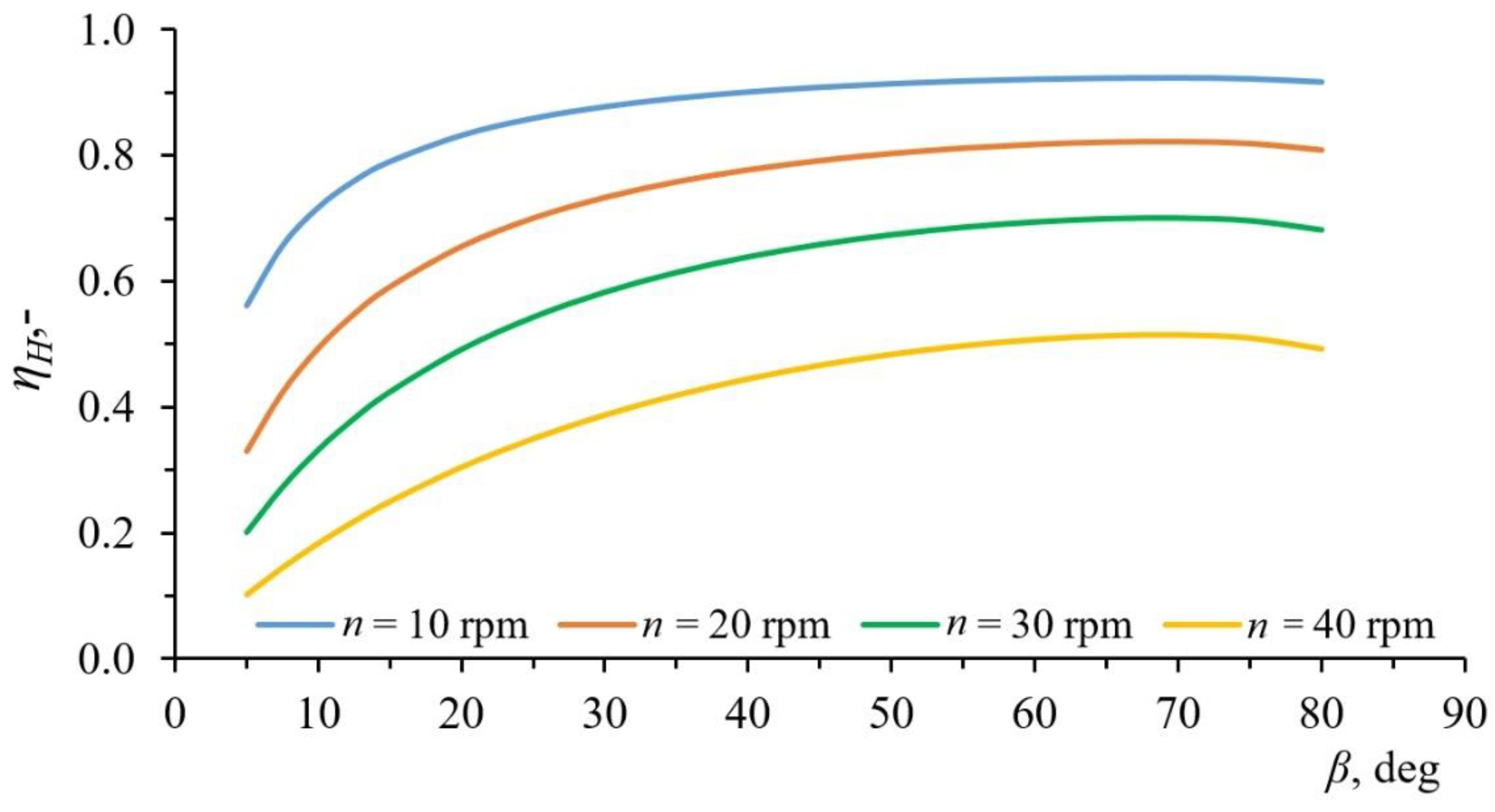
Results of calculations using Equations (18)–(26), made for a single start coil pump (R = 57.5 mm, a = 6 mm) for chosen values of rotational speed n, at the static head H = 1000 mm, are shown in Figure 10. The highest hydraulic efficiency values were achieved for the inclination angle β ≈ 70° (Figure 11). With the increase of rotational speed, a decrease in efficiency can be observed, which results from the linear increase in shear stress along with the increase of fluid velocity. In contrast, in the case of centrifugal pumps the hydraulic efficiency decreases with rotational speed [34,35,36]. For the inclination angle β ≈ 20°, the efficiencies are comparable to those of the Archimedean screw [3,4]. At smaller inclination angles they are even lower due to the increasing drum length and relatively large number of coils. It should be noted that energetic efficiency in the case of wastewater transport may decrease in time as a result of biofilm formation on the wall of coil tubes.
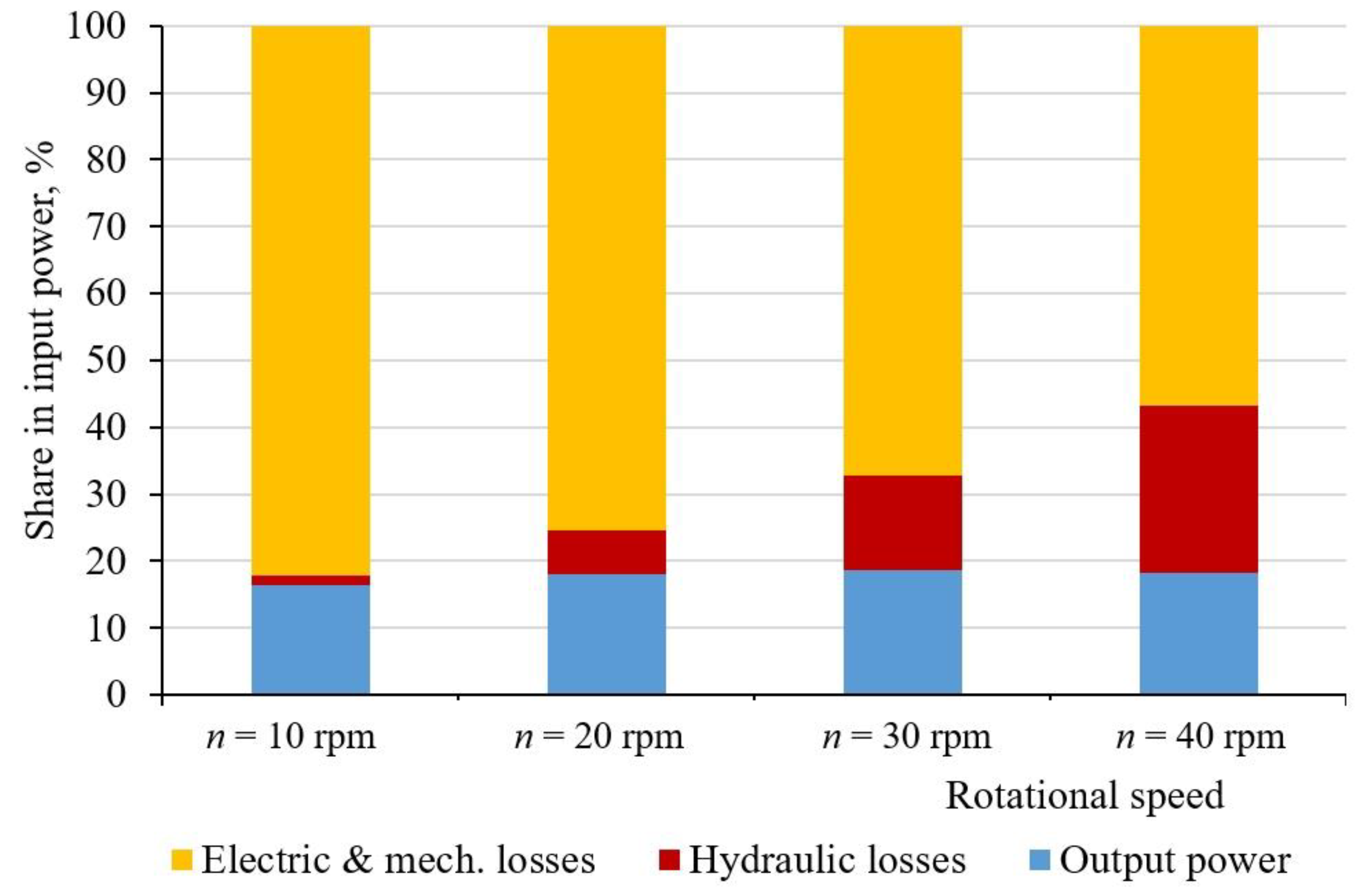
Components of power balance for the experimental coil pump inclined at β = 40° are presented in Figure 12. It can be seen that the hydraulic efficiency of the coil pump is increasing with decreasing rotational speed, however the total efficiency is relatively low due to high electric and mechanical losses. The values of measured mechanical and electrical losses are specific to the tested structure of the coil pump. The use of other bearings on the shaft axis, transmission and engine will change the mutual proportions of the three power components.
Comparing our pump with famous ancient constructions of tubular Archimedean pumps, e.g., with the Augsburg Machine [23], one can observe that in the latter case the drum inclination angle was relatively small (β ≈ 24°), the lead ratio was relatively high (l/D ≈ 6, ψ = 45°), and the drum length to the tube outer diameter ratio was relatively low (LD/D ≈ 18). However, probably due to ancient heavy or fragile materials and primitive power transmissions, the ancient architects decided to build the machine in seven stages.
Providing several starts would increase its lead to pitch ratio, helix inclination angle ψ and power. This problem is similar to determination of the optimal number of blades in Archimedean screw-pumps, which typically have 2–8 blades [26].
Further studies in this direction as well as to optimize the device for a specific application are needed.
Low-speed coil pumps, similarly to Archimedean screw pumps [37], have a great potential to be applied in remote places and be powered by renewable energy sources (wind and solar energy). They may also be driven by running water (sling pumps).
3.3. Scale Effects
The presented results of experimental research were carried out in a laboratory scale reactor. Due to the small diameter of the PVC tube (15 mm) from which the coils were made, it was checked whether there is a capillary effect. For this purpose, a tube section (15 cm) from identical material was moistened and immersed vertically in a beaker with water at an ambient temperature of 25 °C. The inner meniscus of height < 1 mm has occurred at the same level as the outer one. With coils with smaller inner diameters (several mm), the meniscus may deform at the liquid/gas interface, a phenomenon known as pinning [38]. Dimensionless numbers in relationships for fc (Re and De) can be treated as dynamic similarity criteria which regard themselves main scale effects.
4. Conclusions
Based on the idea of the Archimedean screw and our own experiments, a hydraulic model of a low-speed coil pump was developed. A new formula to calculate the pump capacity was successfully validated using measurement results obtained from a laboratory physical model at rotational speeds of 10 and 40 rpm.
The performed experiments confirmed the assumption that with a constant level of submergence of the drum, successive coils with a constant radius are filled to the same level regardless of the coil length. In the tested range of rotational speed of the drum this did not affect the effectiveness of coil filling. Additional experiments allowed us to determine the speed of free filling of coils. At speeds greater than 60–70 rpm filling may be hindered, as the liquid will not be able to fill the coils of inner radius a = 6 mm in time.
With an open tube outlet and a constant pump drum length the pump static head increases proportionally to the tangent of the drum inclination angle. However, the latter cannot be greater than the angle of a helix; therefore the maximum lead depends on the drum inclination angle. In practice, an inclination angle of the drum axis (to the horizontal) close to 87° (at the closest tube winding) makes it possible to install the coil pump almost vertically in standard manholes of sewerage systems. Such installations in small diameter gravity sewerage systems can replace traditional pumping stations and may play the role of in-line treatment units. The low-speed nonpressurized coil pump is a leak-proof variant of an Archimedean screw. Its main disadvantage, namely the lack of direct access to the inner space of the tubes wound around the drum, can be overcome by applying the Archimedean screw with a helically wound lateral strip.
Relative pump yield depends to a differentiated degree on drum and helix inclinations. At relative small helix angles the dependence is rather weak. With increasing helix angles the relative pump yield dramatically decreases for the highest (β = 60°) drum inclination but it may even increase for the smallest (β = 20°) drum inclination to horizontal.
Low-speed coil pumps, similarly to Archimedean screw pumps [29], have great potential to be applied in remote places and be powered by renewable energy sources (wind and solar energy). They may also be driven by running water (sling pumps).
Further studies are needed to improve the efficiency as well as optimize the device for specific applications.
Author Contributions
Conceptualization, R.B. and R.M.; Validation, R.B.; Investigation, R.M., T.N., and M.P.; Writing—Original Draft Preparation, R.B., R.M., and T.N.; Writing—Review & Editing, R.B.; Visualization, T.N.; Supervision, R.B.
Funding
The publication was co-financed within the framework of Ministry of Science and Higher Education programme as “Regional Initiative Excellence” in years 2019–2022, Project No. 005/RID/2018/19.
Acknowledgments
Conflicts of Interest
The authors declare no conflict of interest.
List of symbols
| a | inner radius of the coil tube, m |
| c | chord length, m |
| D | diameter of cylindrical helix, m |
| D | maximum fluid depth in partially filled coil tube, m |
| De | Dean number, -. |
| fc | friction factor for coil tube, - |
| fs | friction factor for a straight pipe, - |
| Fs | shear force in the coil tube, N |
| g | gravitational constant, m s−2 |
| h | submergence depth of the left of tube inlet, m |
| H | static head or height of the helix, m |
| Hm | mean static head, m |
| l | lead, m |
| L | length of helical curve, m |
| L1 | length of cylindrical coil (torus), m |
| Lp | length of liquid pocket, m |
| M | moment of force G about the axis of cylindrical helix, Nm |
| m | number of measurements, - |
| N | number of pockets, - |
| n | rotational speed, rps or rpm |
| Pf | power needed to surmount fluid friction within the coil pump, W |
| Pl | power needed to lift water in the gravity field, W |
| Qp | pump yield, m3 s−1 |
| r | outer radius of the tube, m |
| R | radius of cylindrical helix or torus, m |
| S | sagitta of a circular pocket, m |
| s | length of circular arc, m |
| v | fluid velocity in coil tube, m s−1 |
| V1 | volume of a circular coil (torus), m3 |
| V1l | nner volume of one helical tube coil, m3 |
| Vh | liquid volume in one partly filled coil, m3 |
| Vp | volume of liquid in a shallow pocket (d < 2a), m3 |
| Xc | value calculated using the model, |
| Xea | average measured value, |
| Xei | i-th measured value, |
| α | angle of rotation, rad |
| β | angle of inclination of the axis of rotation to the horizontal, deg. |
| δ | fluid depth in partially filled coil tube, m |
| Δh | water level difference in a coil during rotation, m |
| ε | cross sectional area of flow factor, - |
| ηH | hydraulic efficiency, - |
| ν | kinematic viscosity of the fluid, m2/s |
| ρw | density of water, kg m−3 |
| τ | wall shear stress, N/m2 |
| ψ | angle of inclination of the cylindrical helix to pump baseline, deg. |
References
- Yannopoulos, S.I.; Lyberatos, G.; Theodossiou, N.; Li, W.; Valipour, M.; Tamburrino, A.; Angelakis, A.N. Evolution of water lifting devices (pumps) over the centuries worldwide. Water 2015, 7, 5031–5060. [Google Scholar] [CrossRef]
- Lubitz, D.W. Gap Flow in Archimedes Screws. In Proceedings of the Canadian Society for Mechanical Engineering International Congress 2014, Toronto, ON, Canada, 1–4 June 2014; Available online: http://www.soe.uoguelph.ca/webfiles/wlubitz/Lubitz_CSME_2014_Archimedes_gap_flow.pdf (accessed on 10 February 2019).
- Mueller, G.; Senior, J. Simplified theory of Archimedean screws. J. Hydraul. Res. 2009, 47, 666–669. [Google Scholar] [CrossRef]
- Stergiopoulou, A.; Stergiopoulos, V.; Kalkani, E. Back to the future: Rediscovering the Archimedean screws as modern turbines for harnessing Greek small hydropower potential. Fresenius Environ. Bull. 2013, 22, 2053–2058. [Google Scholar]
- Elbatran, A.H.; Yaakob, O.B.; Ahmed Yasser, M.; Shabara, H.M. Operation, performance and economic analysis of low head micro-hydropower turbines for rural and remote areas: A review. Renew. Sustain. Energy Rev. 2015, 43, 40–50. [Google Scholar] [CrossRef]
- Tailer, P. The Spiral Pump. A High Lift, Slow Turning Pump. 2005. Available online: https://lurkertech.com/water/pump/tailer/ access in July 2018 (accessed on 5 February 2019).
- Belcher, A.E. The rotary scroll collector. North. Eng. 1990, 22, 27–33. Available online: https://scholarworks.alaska.edu/bitstream/handle/11122/1764/The%20Northern%20Engineer%20Vol%2022%20No%201.pdf?sequence=1 (accessed on 5 February 2019).
- Deane, J.H.B.; Bevan, J.J. A hydrostatic model of the Wirtz pump. Proc. R. Soc. A Math. Phys. 2018, 474. [Google Scholar] [CrossRef]
- Jokiel, M.; Wagner, L.; Mansour, M.; Kaiser, N.M.; Zähringer, K.; Janiga, G.; Nigam, K.D.P.; Thévenin, D.; Sundmacher, K. Measurement and simulation of mass transfer and backmixing behavior in a gas-liquid helically coiled tubular reactor. Chem. Eng. Sci. 2017, 170, 410–421. [Google Scholar] [CrossRef] [Green Version]
- Kováts, P.; Pohl, D.; Thévenin, D.; Zähringer, K. Optical determination of oxygen mass transfer in a helically-coiled pipe compared to a straight horizontal tube. Chem. Eng. Sci. 2018, 190, 273–285. [Google Scholar] [CrossRef]
- Jokiel, M.; Kaiser, N.M.; Kováts, P.; Mansour, M.; Zähringer, K.; Nigam, K.D.P.; Sundmacher, K. Helically coiled segmented flow tubular reactor for the hydroformylation of long-chain olefins in a thermomorphic multiphase system. Chem. Eng. J. 2018. [Google Scholar] [CrossRef]
- Zhang, C.; Ferrell, A.R.; Nandakumar, K. Study of a toroidal-helical pipe as an innovative static mixer in laminar flows. Chem. Eng. J. 2019, 359, 446–458. [Google Scholar] [CrossRef]
- Collett, J. Hydro-powered water lifting devices for irrigation. In Proceedings of the FAO/DANIDA, Bangkok, Thailand, 4–14 December 1979; Available online: https://www.ircwash.org/sites/default/files/71FAO79-159.4.pdf (accessed on 25 February 2019).
- Naegel, L.C.A.; Real, J.G.; Mazaredo, A.M. Designing a spiral pump for irrigation. Waterlines 1991, 10, 30–31. [Google Scholar] [CrossRef]
- Mortimer, G.H.; Annable, R. The coil pump—Theory and practice. J. Hydraul. Res. 1984, 22, 9–22. [Google Scholar] [CrossRef]
- Mortimer, G.H. The Coil Pumps. Ph.D. Thesis, University of Loughborough, Loughborough, UK, 1988. Available online: https://dspace.lboro.ac.uk/dspace-jspui/bitstream/2134/16296/4/Thesis-1988-Mortimer.pdf (accessed on 5 February 2019).
- Matz, R.; Błażejewski, R.; Nawrot, T.; Spychała, M.; Jeżowska, J.; Makowska, M. Hydraulic characteristics of innovative tubular reactor with helical rotors. Przem. Chem. 2015, 11, 216. (In Polish) [Google Scholar] [CrossRef]
- Nawrot, T.; Matz, R.; Błażejewski, R.; Spychała, M. A Case Study of a Small Diameter Gravity Sewerage System in Zolkiewka Commune. Pol. Water 2018, 10, 1358. [Google Scholar] [CrossRef]
- Hilton, D.J. The inclined coil pump. Waterlines 1986, 5, 12–13. [Google Scholar] [CrossRef]
- Modi, V.J.; Nourbaksh, A. Design and parametric performance of a rotating helical coil pump. In Fluid Power; Maeda, T., Ed.; 1993; pp. 249–254. Available online: www.jstage.jst.go.jp/article/isfp1989/1993/2/1993_2_249/_pdf (accessed on 5 February 2019).
- Abdel-Basier, I.A. Coil Pump Design and Performance. Ph.D. Thesis, Alexandria University, Alexandria, Egypt, 2005. [Google Scholar]
- Koetsier, T.; Blauwendraat, H. The Archimedean Screw-Pump: A Note on Its Invention and the Development of the Theory. In Proceedings of the International Symposium on History of Machines and Mechanisms, Cassino, Italy, 12–15 May 2004; Springer: Dordrecht, The Netherlands. [Google Scholar] [CrossRef]
- Kassab, S.Z.; Abdel-Naby, A.A.; Abdel-Basier, I.A. Coil pump performance under variable operating conditions. In Proceedings of the 9th International Water Technology Conference, Sharm El-Sheikh, Egypt, 17–20 March 2005; Available online: http://iwtc.info/2005_pdf/09-5.pdf (accessed on 14 February 2019).
- Kassab, S.Z.; Abdel-Naby, A.A.; Abdel-Basier, I.A. Performance of multi-layers coil pump. In Proceedings of the 10th International Water Technology Conference, Alexandria, Egypt, 23–25 March 2006; Available online: http://www.iwtc.info/2006_pdf/06-2.pdf (accessed on 14 February 2019).
- Rorres, C. The turn of the screw: Optimal design of an Archimedes screw. J. Hydraul. Eng. 2000, 126, 72–80. [Google Scholar] [CrossRef]
- Troskolański, A.T. Dictionary of Hydraulic Machinery; Elsevier: Amsterdam, The Netherlands, 1985; ISBN 978-8301023805. [Google Scholar]
- Witten, I.H.; Frank, E.; Hall, M.A. Data Mining: Practical Machine Learning Tools and Techniques; Elsevier Inc.: Amsterdam, The Netherlands, 2011. [Google Scholar] [CrossRef]
- Hochheimer, J.N.; Wheaton, F. Biological filters: Trickling and RBC design. In Proceedings of the Second International Conference on Recirculating Aquaculture, Roanoke, VA, USA, 16–19 July 1998; Available online: http://web.deu.edu.tr/atiksu/ana52/trirbcdes.pdf (accessed on 14 February 2019).
- White, C.M.; Appleton, E.V. Streamline flow through curved pipe. Proc. R. Soc. Lond. 1929, 123, 645–663. [Google Scholar] [CrossRef]
- Ito, H. Friction factors for turbulent flow in curved pipes. J. Basic Eng. 1959, 82, 123–132. [Google Scholar] [CrossRef]
- Hart, J.; Ellenberger, J.; Hamersma, P.J. Single- and two-phase flow through helically coiled tubes. Chem. Eng. Sci. 1988, 43, 775–783. [Google Scholar] [CrossRef]
- Ghobadi, M.; Muzychka, Y.S. A review of heat transfer and pressure drop correlations for laminar flow in curved circular ducts. Heat Transf. Eng. 2016, 37, 815–839. [Google Scholar] [CrossRef]
- Fsadni, A.M.; Whitty, J.P.M. A review on the twophase pressure drop characteristics in helically coiled tubes. Appl. Therm. Eng. 2016, 103, 616–638. [Google Scholar] [CrossRef]
- Liu, M.; Tan, L.; Cao, S. Theoretical model of energy performance prediction and BEP determination for centrifugal pump as turbine. Energy 2019, 172, 712–732. [Google Scholar] [CrossRef]
- Wilk, A. Hydraulic Efficiencies of Impeller and Pump Obtained by Means of Theoretical Calculations and Laboratory Measurements for High Speed Impeller Pump with Open-Flow Impeller with Radial Blades. Int. J. Mech. 2010, 4. Available online: http://www.naun.org/main/NAUN/mechanics/19-456.pdf (accessed on 14 February 2019).
- Suh, S.H.; Kyung-Wuk, K.; Kim, H.H.; Cho, M.T.; Yoon, I.S. A study on multistage centrifugal pump performance characteristics for variable speed drive system. Procedia Eng. 2015, 105, 270–275. [Google Scholar] [CrossRef]
- Fiardi, E. Preliminary design of Archimedean screw turbine prototype for remote area power supply. JOMAse 2014, 5, 1–12. Available online: http://isomase.org/JOMAse/Vol.5%20Mar%202014/5-4.pdf (accessed on 14 February 2019).
- Myers, M.R.; Cave, H.M.; Krumdieck, S.P. Surface Tension Effects on Liquid Flow in Small Plastic Tubes When Gas Bubbles Are Present. Proc. Inst. Mech. Eng. C 2005, 219, 853–857. [Google Scholar] [CrossRef]
Figure 1.
A diagram of a helix opq wound around a cylindrical drum (adapted from Koetsier and Blauwendraat (2004)).
Figure 1.
A diagram of a helix opq wound around a cylindrical drum (adapted from Koetsier and Blauwendraat (2004)).

Figure 2.
Heights of points on the cylindrical helix on inclined (β = 40°), vertical (β = 90°), and horizontal (β = 0°) cylinder of radius R = 5.75 cm at the helix inclination angle ψ = 3° according to Equation (1).
Figure 2.
Heights of points on the cylindrical helix on inclined (β = 40°), vertical (β = 90°), and horizontal (β = 0°) cylinder of radius R = 5.75 cm at the helix inclination angle ψ = 3° according to Equation (1).

Figure 3.
Cross-section of one nearly vertical coil (β = 0) at the lower drum end: (a) still and (b) rotating.
Figure 3.
Cross-section of one nearly vertical coil (β = 0) at the lower drum end: (a) still and (b) rotating.

Figure 4.
Vertical and cross-section B-B of a tube coil partly filled with liquid.

Figure 5.
Side view and longitudinal and cross-sections of the experimental set-up: 1: tubes; 2: stiffening rods; 3: shaft; 4: electric motor; 5: container; 6: electronic balance; 7: inlet of water; 8: overflow; 9: drum; 10: collar; 11: tank.
Figure 5.
Side view and longitudinal and cross-sections of the experimental set-up: 1: tubes; 2: stiffening rods; 3: shaft; 4: electric motor; 5: container; 6: electronic balance; 7: inlet of water; 8: overflow; 9: drum; 10: collar; 11: tank.

Figure 6.
Side views of partly filled coils wound on the motionless drum inclined at angle (a) β = 20°, (b) β = 40°, (c) β = 60°, (d) β = 83° to the horizontal plane; the last shows the filling of coils caused by the liquid back flow after exceeding a critical angle β = 90 − ψ.
Figure 6.
Side views of partly filled coils wound on the motionless drum inclined at angle (a) β = 20°, (b) β = 40°, (c) β = 60°, (d) β = 83° to the horizontal plane; the last shows the filling of coils caused by the liquid back flow after exceeding a critical angle β = 90 − ψ.

Figure 7.
Comparison of calculated (Qp cal—Equation (12)) and measured (Qp meas) coil pump yields.

Figure 8.
Calculated relative pump yield for different drum and helix inclinations.

Figure 9.
Theoretical fill time of half coil (R = 57.5 mm) of tube of inner diameter 12 mm vs. half-turn period as a function of rotational speed. Dotted lines show the confidence interval based on sample standard deviation (m = 10).
Figure 9.
Theoretical fill time of half coil (R = 57.5 mm) of tube of inner diameter 12 mm vs. half-turn period as a function of rotational speed. Dotted lines show the confidence interval based on sample standard deviation (m = 10).

Figure 10.
Comparison of calculated frictional head losses and those measured in a rotating torus of radius R = 8.8 mm (black dots).
Figure 10.
Comparison of calculated frictional head losses and those measured in a rotating torus of radius R = 8.8 mm (black dots).

Figure 11.
Hydraulic (theoretical) efficiency of a single start coil pump (R = 57.5 mm; a = 6 mm; r = 7.5 mm) for chosen values of rotational speed n, static head H = 1000 mm, and ψ = 3 deg.
Figure 11.
Hydraulic (theoretical) efficiency of a single start coil pump (R = 57.5 mm; a = 6 mm; r = 7.5 mm) for chosen values of rotational speed n, static head H = 1000 mm, and ψ = 3 deg.

Figure 12.
Components of power balance for the experimental coil pump inclined at β = 40°.


Table 1.
Experimental design.
| No. of Experiment | 1 | 2 | 3 | 4 | 5 | 6 | 7 | 8 | 9 | 10 | 11 | 12 |
| Inclination angle, β, deg. | 20 | 40 | 60 | |||||||||
| Rotational speed, n, rpm | 10 | 20 | 30 | 40 | 10 | 20 | 30 | 40 | 10 | 20 | 30 | 40 |
Table 2.
Comparison of calculated (Qp cal—Equation (12) and measured (Qp meas) coil pump yields.
| Rotational Speed, n, rpm | 10 | 20 | 30 | 40 |
| Number of measurements, m | 96 | 96 | 96 | 96 |
| Pump yield, Qp meas, m3/s | 3.3 × 10⁻⁶ | 6.6 × 10⁻⁶ | 9.8 × 10⁻⁶ | 13.2 × 10⁻⁶ |
| Pump yield, Qp cal, m3/s | 3.4 × 10⁻⁶ | 6.8 × 10⁻⁶ | 10.2 × 10⁻⁶ | 13.6 × 10⁻⁶ |
| CV(RSME), % (see Equation (17)) | 0.20 | 0.16 | 0.59 | 4.15 |
© 2019 by the authors. Licensee MDPI, Basel, Switzerland. This article is an open access article distributed under the terms and conditions of the Creative Commons Attribution (CC BY) license (http://creativecommons.org/licenses/by/4.0/).
Share and Cite
MDPI and ACS Style
Matz, R.; Błażejewski, R.; Nawrot, T.; Pawlak, M. Hydraulic Capacity and Efficiency of a Low-Speed Nonpressurized Coil Pump. Water 2019, 11, 1659. https://doi.org/10.3390/w11081659
AMA Style
Matz R, Błażejewski R, Nawrot T, Pawlak M. Hydraulic Capacity and Efficiency of a Low-Speed Nonpressurized Coil Pump. Water. 2019; 11(8):1659. https://doi.org/10.3390/w11081659
Chicago/Turabian StyleMatz, Radosław, Ryszard Błażejewski, Tadeusz Nawrot, and Maciej Pawlak. 2019. "Hydraulic Capacity and Efficiency of a Low-Speed Nonpressurized Coil Pump" Water 11, no. 8: 1659. https://doi.org/10.3390/w11081659
Note that from the first issue of 2016, this journal uses article numbers instead of page numbers. See further details here.