Convective Bubbly Flow of Water in an Annular Pipe: Role of Total Dissolved Solids on Heat Transfer Characteristics and Bubble Formation

 ,
,  , , , and
Abstract
:
1. Introduction
2. Experimental
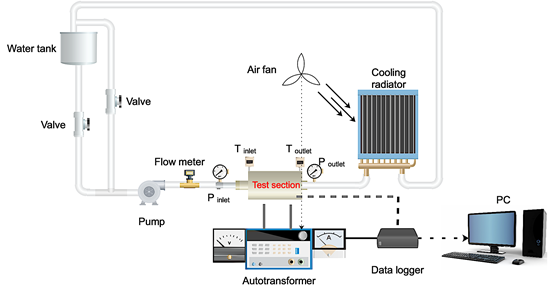
2.1. Test Setup
2.2. Heat Loss Analysis and Analysis of Uncertainty
3. Results
3.1. HTC or Heat Transfer Coefficient
3.2. Bubble Diameter
3.3. Contact Angle
3.4. Comparison Against the Developed Models
3.5. Flow Rate of Water
3.6. Chemical Composition and Thermal Conductivity Measurement
4. Conclusions
- (1)
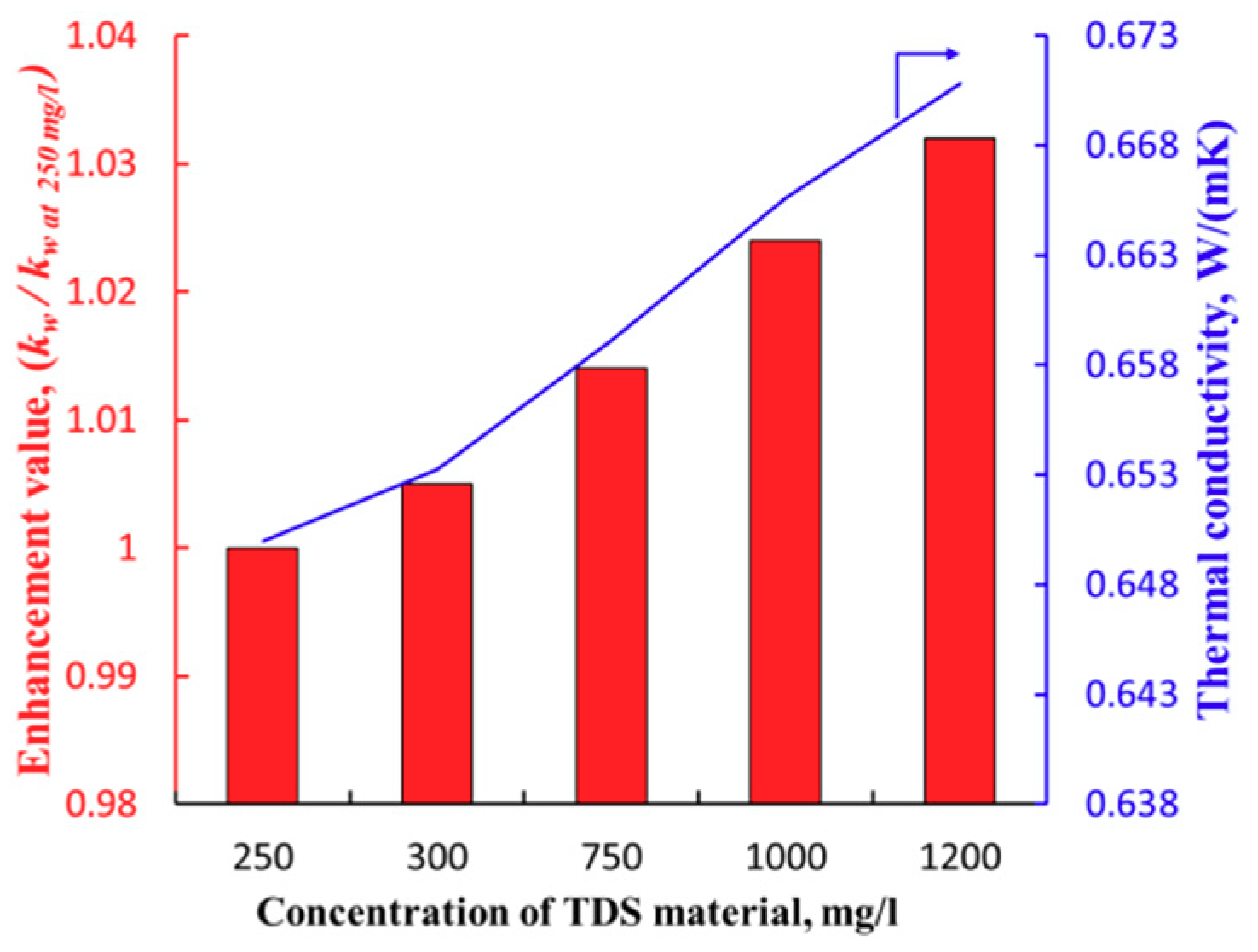
- It was identified that the presence of total dissolved solid materials can improve the thermal conductivity of water, and plausibly influences the bubble formation characteristics of the system. Results show that the thermal conductivity of water can be improved by ~3.2% when the TDS materials increased from 250 mg/L to 1200 mg/L.
- (2)
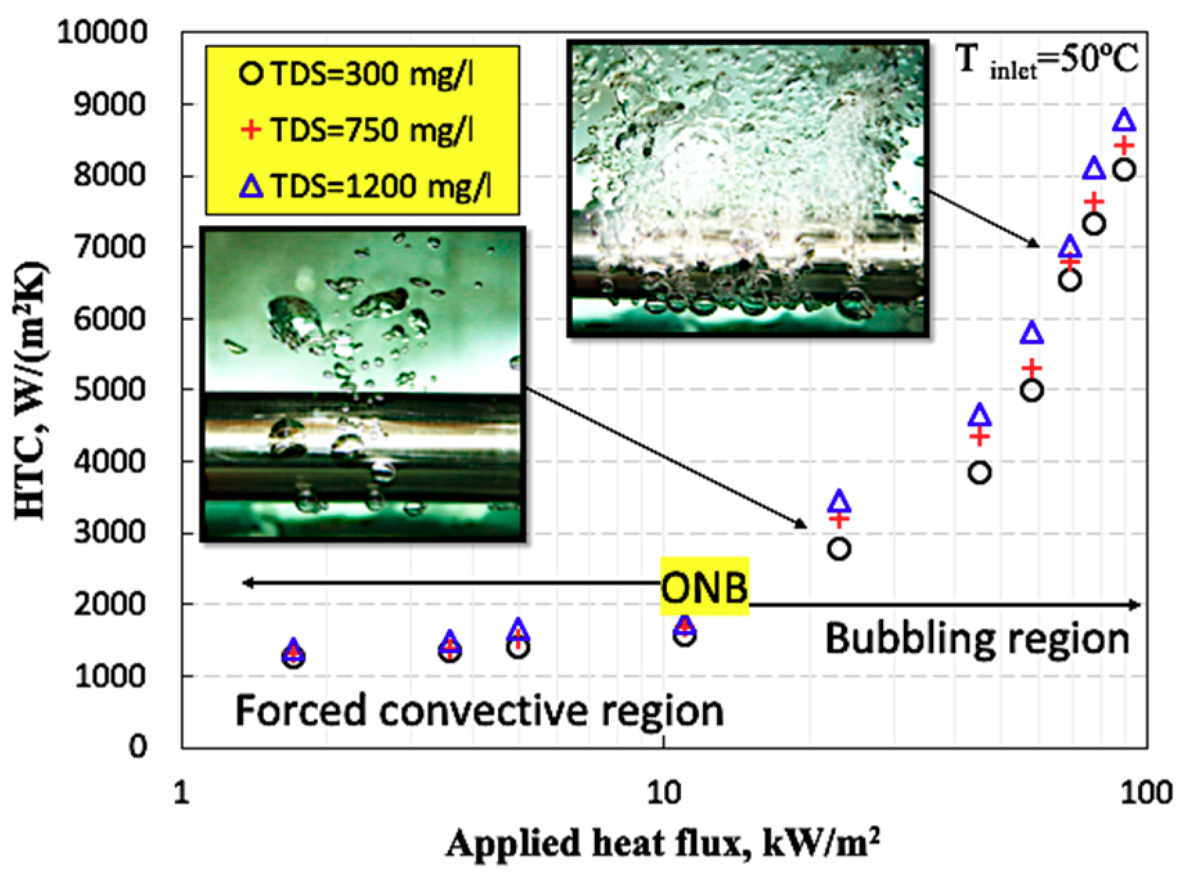
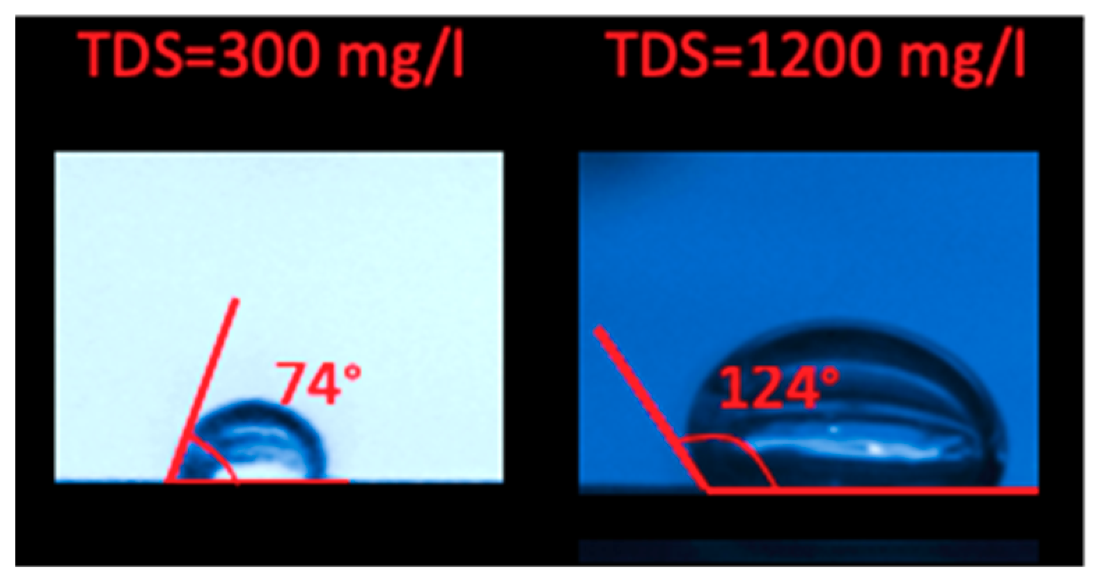
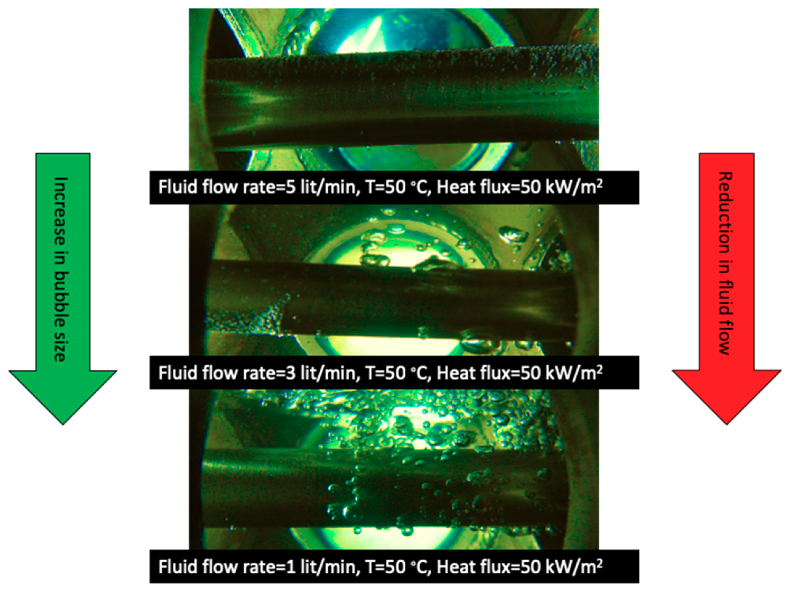
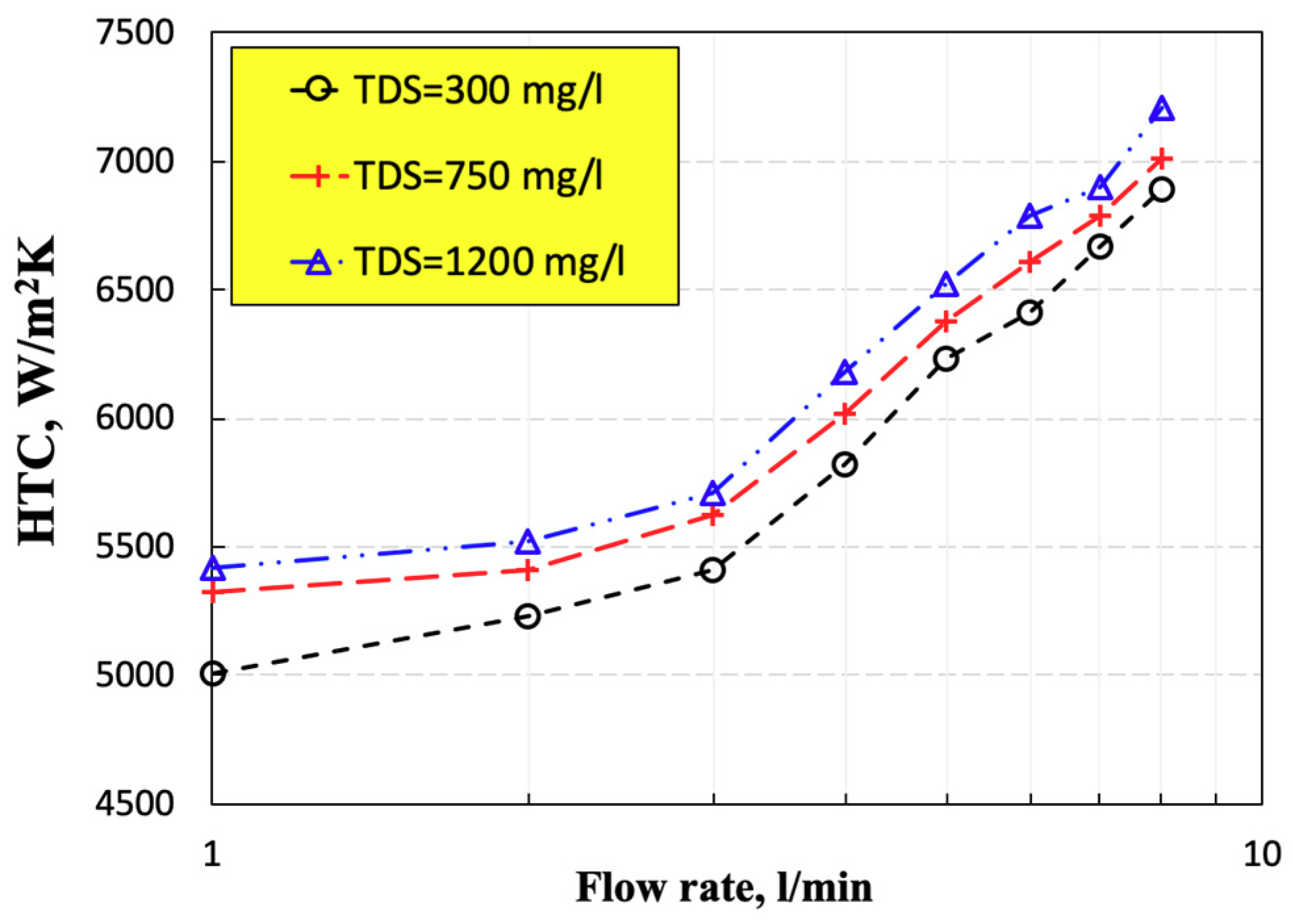
- Increasing the TDS mass fraction resulted in larger bubble diameters, the contact angle between the bubble and the heating surface increased, and the heat transfer coefficient of the system was enlarged. It was also identified that the flow rate of water can considerably change the bubble diameter size, such that for Q = 5 L/min, suppression of bubble formation occurred at subcooled regime. Hence, bubbles were larger at low flow rates, e.g., 1 L/min. The highest heat transfer coefficient of >9000 W/(m2K) was reported for water with a TDS value of 1200 mg/L at flow rate of 8 L/min, despite the reduction in the bubble size, as the thermal boundary layer was renewed quickly.
- (3)
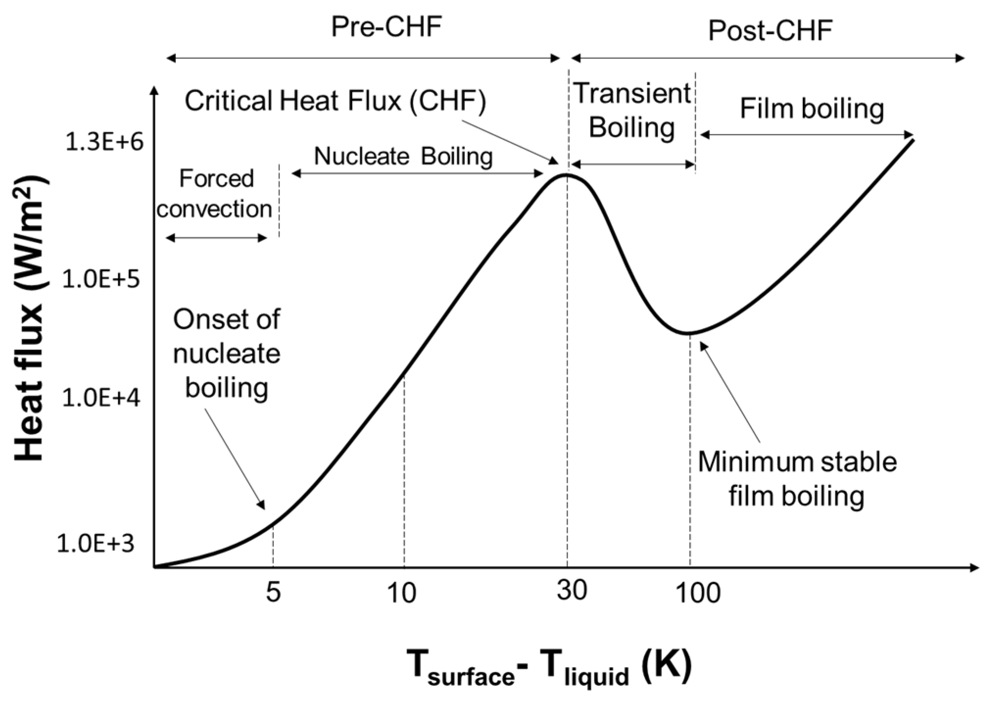
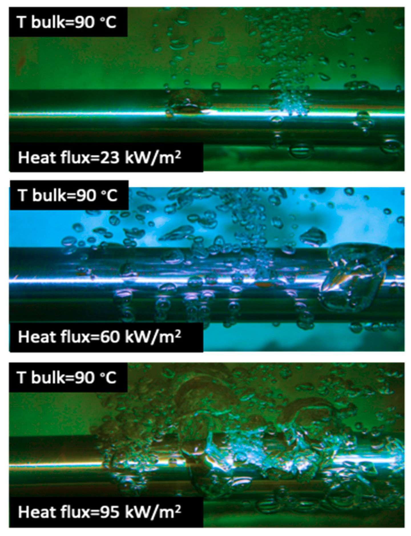
- Forced convective heat transfer and nucleate boiling were the dominant mechanisms of heat transfer in the system, which were separated with a point referred to as onset of nucleate boiling, in which the first bubbles form on the surface. Thereby, the presence of TDS materials in water can promote the bubble formation, resulting in the enhancement of the mixing and heat transfer coefficient.
- (4)
- Overall, the bubble formation—despite its plausible heat transfer characteristics—can have some disadvantages, such as cavitation, corrosion, and wear, which need further study. Especially for the metallic pipes, wear can induce a massive corrosion to the system over time. A comprehensive study in this area is highly recommended. Also, the influence of TDS on physical properties of water should be studied, along with its effect on the boiling mechanism. Studying these topics can broaden the knowledge of two-phase heat transfer.
Author Contributions
Funding
Acknowledgments
Conflicts of Interest
References
- Bergles, A.E.; Collier, J.; Delhaye, J.M.; Hewitt, G.; Mayinger, F. Two-Phase Flow and Heat Transfer in the Power and Process Industries; Hemisphere Publishing Corp.: New York, NY, USA, 1981. [Google Scholar]
- Saha, K.; Agarwal, A.K.; Ghosh, K.; Som, S. (Eds.) Two-Phase Flow for Automotive and Power Generation Sectors; Springer: Singapore, 2019. [Google Scholar]
- Kandlikar, S.G. Handbook of Phase Change: Boiling and Condensation; Routledge: Abingdon-on-Thames, UK, 2018. [Google Scholar]
- Marcinichen, J.B.; Thome, J.R.; Michel, B. Cooling of microprocessors with micro-evaporation: A novel two-phase cooling cycle. Int. J. Refrig. 2010, 33, 1264–1276. [Google Scholar] [CrossRef]
- Cengel, Y. Heat an Mass Transfer: Fundamentals and Applications; McGraw-Hill: USA, 2014. [Google Scholar]
- Murshed, S.S.; De Castro, C.N. A critical review of traditional and emerging techniques and fluids for electronics cooling. Renew. Sustain. Energy Rev. 2017, 78, 821–833. [Google Scholar] [CrossRef]
- Storm, K. Chapter 4—Waste heat boiler. In Industrial Process Plant Construction Estimating and Man-Hour Analysis; Storm, K., Ed.; Gulf Professional Publishing: Oxford, UK, 2019; pp. 67–78. [Google Scholar]
- Park, K.-J.; Jung, D. Boiling heat transfer enhancement with carbon nanotubes for refrigerants used in building air-conditioning. Energy Build. 2007, 39, 1061–1064. [Google Scholar] [CrossRef]
- Ding, W.; Zhang, P.; Li, Y.; Xia, H.; Wang, D.; Tao, X. Effect of latent heat in boiling water on the synthesis of gold nanoparticles of different sizes by using the turkevich method. ChemPhysChem 2015, 16, 447–454. [Google Scholar] [CrossRef] [PubMed]
- Moita, A.; Teodori, E.; Moreira, A. Influence of surface topography in the boiling mechanisms. Int. J. Heat Fluid Flow 2015, 52, 50–63. [Google Scholar] [CrossRef]
- Magnini, M.; Thome, J. A cfd study of the parameters influencing heat transfer in microchannel slug flow boiling. Int. J. Therm. Sci. 2016, 110, 119–136. [Google Scholar] [CrossRef]
- Piasecka, M. Impact of selected parameters on refrigerant flow boiling heat transfer and pressure drop in minichannels. Int. J. Refrig. 2015, 56, 198–212. [Google Scholar] [CrossRef]
- Pothukuchi, H.; Kelm, S.; Patnaik, B.; Prasad, B.; Allelein, H.-J. Numerical investigation of subcooled flow boiling in an annulus under the influence of eccentricity. Appl. Therm. Eng. 2018, 129, 1604–1617. [Google Scholar] [CrossRef]
- Guo, D.; Sun, D.; Li, Z.; Tao, W. Phase change heat transfer simulation for boiling bubbles arising from a vapor film by the voset method. Numer. Heat Transf. Part A Appl. 2011, 59, 857–881. [Google Scholar] [CrossRef]
- Forster, H.; Zuber, N. Dynamics of vapor bubbles and boiling heat transfer. AIChE J. 1955, 1, 531–535. [Google Scholar] [CrossRef]
- Lu, M.-C.; Tong, J.-R.; Wang, C.-C. Investigation of the two-phase convective boiling of hfo-1234yf in a 3.9 mm diameter tube. Int. J. Heat Mass Transf. 2013, 65, 545–551. [Google Scholar] [CrossRef]
- Yan, J.; Bi, Q.; Liu, Z.; Zhu, G.; Cai, L. Subcooled flow boiling heat transfer of water in a circular tube under high heat fluxes and high mass fluxes. Fusion Eng. Des. 2015, 100, 406–418. [Google Scholar] [CrossRef]
- Kim, J. Review of nucleate pool boiling bubble heat transfer mechanisms. Int. J. Multiph. Flow 2009, 35, 1067–1076. [Google Scholar] [CrossRef]
- Jung, S.; Kim, H. An experimental method to simultaneously measure the dynamics and heat transfer associated with a single bubble during nucleate boiling on a horizontal surface. Int. J. Heat Mass Transf. 2014, 73, 365–375. [Google Scholar] [CrossRef]
- Pan, L.-M.; Tan, Z.-W.; Chen, D.-Q.; Xue, L.-C. Numerical investigation of vapor bubble condensation characteristics of subcooled flow boiling in vertical rectangular channel. Nucl. Eng. Des. 2012, 248, 126–136. [Google Scholar] [CrossRef]
- Julia, J.E.; Hibiki, T. Flow regime transition criteria for two-phase flow in a vertical annulus. Int. J. Heat Fluid Flow 2011, 32, 993–1004. [Google Scholar] [CrossRef]
- Hernández, L.; Julia, J.E.; Ozar, B.; Hibiki, T.; Ishii, M. Flow regime identification in boiling two-phase flow in a vertical annulus. J. Fluids Eng. 2011, 133, 091304. [Google Scholar] [CrossRef]
- Kandlikar, S.G. A general correlation for saturated two-phase flow boiling heat transfer inside horizontal and vertical tubes. J. Heat Transf. 1990, 112, 219–228. [Google Scholar] [CrossRef]
- Sarafraz, M.M.; Peyghambarzadeh, S.M.; Vaeli, N. Subcooled flow boiling heat transfer of ethanol aqueous solutions in vertical annulus space. Chem. Ind. Chem. Eng. Q. 2012, 18, 315–327. [Google Scholar] [CrossRef]
- Brooks, C.S.; Ozar, B.; Hibiki, T.; Ishii, M. Interfacial area transport of subcooled boiling flow in a vertical annulus. Nucl. Eng. Des. 2014, 268, 152–163. [Google Scholar] [CrossRef]
- Sadeghi, R.; Shadloo, M.S.; Hooman, K. Numerical investigation of the natural convection film boiling around elliptical tubes. Numer. Heat Transf. Part A Appl. 2016, 70, 707–722. [Google Scholar] [CrossRef]
- Lahey, R., Jr.; Ohkawa, K. An experimental investigation of phase distribution in an eccentric annulus. Int. J. Multiph. Flow 1989, 15, 447–457. [Google Scholar] [CrossRef]
- Kelessidis, V.; Dukler, A. Modeling flow pattern transitions for upward gas-liquid flow in vertical concentric and eccentric annuli. Int. J. Multiph. Flow 1989, 15, 173–191. [Google Scholar] [CrossRef]
- Osamusali, S.; Chang, J. Two-phase flow regime transition in a horizontal pipe and annulus flow under gas–liquid two-phase flow. ASME Fed. 1988, 72, 63–69. [Google Scholar]
- Ekberg, N.; Ghiaasiaan, S.; Abdel-Khalik, S.; Yoda, M.; Jeter, S. Gas–liquid two-phase flow in narrow horizontal annuli. Nucl. Eng. Des. 1999, 192, 59–80. [Google Scholar] [CrossRef]
- Thorncroft, G.E.; Klausner, J.F.; Mei, R. An experimental investigation of bubble growth and detachment in vertical upflow and downflow boiling. Int. J. Heat Mass Transf. 1998, 41, 3857–3871. [Google Scholar] [CrossRef]
- Bibeau, E.L.; Salcudean, M. A study of bubble ebullition in forced-convective subcooled nucleate boiling at low pressure. Int. J. Heat Mass Transf. 1994, 37, 2245–2259. [Google Scholar] [CrossRef]
- Situ, R.; Hibiki, T.; Ishii, M.; Mori, M. Bubble lift-off size in forced convective subcooled boiling flow. Int. J. Heat Mass Transf. 2005, 48, 5536–5548. [Google Scholar] [CrossRef] [Green Version]
- Chen, C.A.; Chang, W.R.; Li, K.W.; Lie, Y.M.; Lin, T.F. Subcooled flow boiling heat transfer of r-407c and associated bubble characteristics in a narrow annular duct. Int. J. Heat Mass Transf. 2009, 52, 3147–3158. [Google Scholar] [CrossRef]
- Gerardi, C.; Buongiorno, J.; Hu, L.-W.; McKrell, T. Study of bubble growth in water pool boiling through synchronized, infrared thermometry and high-speed video. Int. J. Heat Mass Transf. 2010, 53, 4185–4192. [Google Scholar] [CrossRef]
- Sugrue, R.; Buongiorno, J.; McKrell, T. An experimental study of bubble departure diameter in subcooled flow boiling including the effects of orientation angle, subcooling, mass flux, heat flux, and pressure. Nucl. Eng. Des. 2014, 279, 182–188. [Google Scholar] [CrossRef] [Green Version]
- Lazarek, G.M.; Black, S.H. Evaporative heat transfer, pressure drop and critical heat flux in a small vertical tube with r-113. Int. J. Heat Mass Transf. 1982, 25, 945–960. [Google Scholar] [CrossRef]
- Jung, D.S.; McLinden, M.; Radermacher, R.; Didion, D. Horizontal flow boiling heat transfer experiments with a mixture of r22/r114. Int. J. Heat Mass Transf. 1989, 32, 131–145. [Google Scholar] [CrossRef]
- Bao, Z.; Fletcher, D.; Haynes, B. Flow boiling heat transfer of freon r11 and hcfc123 in narrow passages. Int. J. Heat Mass Transf. 2000, 43, 3347–3358. [Google Scholar] [CrossRef]
- Yeoh, G.H.; Tu, J.Y. A unified model considering force balances for departing vapour bubbles and population balance in subcooled boiling flow. Nucl. Eng. Des. 2005, 235, 1251–1265. [Google Scholar] [CrossRef]
- Chang, Y.; Ferng, Y. Experimental investigation on bubble dynamics and boiling heat transfer for saturated pool boiling and comparison data with previous works. Appl. Therm. Eng. 2019, 154, 284–293. [Google Scholar] [CrossRef]
- Wang, J.; Cheng, Y.; Li, X.-B.; Li, F.-C. Experimental and lbm simulation study on the effect of bubbles merging on flow boiling. Int. J. Heat Mass Transf. 2019, 132, 1053–1061. [Google Scholar] [CrossRef]
- Yin, X.; Tian, Y.; Zhou, D.; Wang, N. Numerical study of flow boiling in an intermediate-scale vertical tube under low heat flux. Appl. Therm. Eng. 2019, 153, 739–747. [Google Scholar] [CrossRef]
- Eraghubi, M.; Di Marco, P.; Robinson, A. Low mass flux upward vertical forced flow boiling of hfe7000. Exp. Therm. Fluid Sci. 2019, 102, 291–301. [Google Scholar] [CrossRef]
- Suleman, M.; Ramzan, M.; Ahmad, S.; Lu, D.; Muhammad, T.; Chung, J.D. A numerical simulation of silver–water nanofluid flow with impacts of newtonian heating and homogeneous–heterogeneous reactions past a nonlinear stretched cylinder. Symmetry 2019, 11, 295. [Google Scholar] [CrossRef]
- Saif, R.S.; Hayat, T.; Ellahi, R.; Muhammad, T.; Alsaedi, A. Darcy–forchheimer flow of nanofluid due to a curved stretching surface. Int. J. Numer. Methods Heat Fluid Flow 2019, 29, 2–20. [Google Scholar] [CrossRef]
- Sarafraz, M.M.; Arjomandi, M. Contact angle and heat transfer characteristics of a gravity-driven film flow of a particulate liquid metal on smooth and rough surfaces. Appl. Therm. Eng. 2019, 149, 602–612. [Google Scholar] [CrossRef]
- Peyghambarzadeh, S.M.; Sarafraz, M.M.; Vaeli, N.; Ameri, E.; Vatani, A.; Jamialahmadi, M. Forced convective and subcooled flow boiling heat transfer to pure water and n-heptane in an annular heat exchanger. Ann. Nucl. Energy 2013, 53, 401–410. [Google Scholar] [CrossRef]
- Sarafraz, M.M.; Arya, H.; Saeedi, M.; Ahmadi, D. Flow boiling heat transfer to mgo-therminol 66 heat transfer fluid: Experimental assessment and correlation development. Appl. Therm. Eng. 2018, 138, 552–562. [Google Scholar] [CrossRef]
- Sarafraz, M.M.; Hormozi, F. Scale formation and subcooled flow boiling heat transfer of cuo–water nanofluid inside the vertical annulus. Exp. Therm. Fluid Sci. 2014, 52, 205–214. [Google Scholar] [CrossRef]
- Sarafraz, M.M.; Hormozi, F. Forced convective and nucleate flow boiling heat transfer to alumnia nanofluids. Period. Polytech. Chem. Eng. 2014, 58, 37–46. [Google Scholar] [CrossRef]
- Sarafraz, M.M.; Hormozi, F.; Peyghambarzadeh, S.M.; Vaeli, N. Upward flow boiling to di-water and cuo nanofluids inside the concentric annuli. J. Appl. Fluid Mech. 2015, 8, 651–659. [Google Scholar]
- Goshayeshi, H.R.; Goodarzi, M.; Safaei, M.R.; Dahari, M. Experimental study on the effect of inclination angle on heat transfer enhancement of a ferrofluid in a closed loop oscillating heat pipe under magnetic field. Exp. Therm Fluid Sci. 2016, 74, 265–270. [Google Scholar] [CrossRef]
- Sarafraz, M.M.; Peyghambarzadeh, S.M. Experimental study on subcooled flow boiling heat transfer to water–diethylene glycol mixtures as a coolant inside a vertical annulus. Exp. Therm. Fluid Sci. 2013, 50, 154–162. [Google Scholar] [CrossRef]
- Nikkhah, V.; Sarafraz, M.M.; Hormozi, F. Application of spherical copper oxide (ii) water nano-fluid as a potential coolant in a boiling annular heat exchanger. Chem. Biochem. Eng. Q. 2015, 29, 405–415. [Google Scholar] [CrossRef]
- Salari, E.; Peyghambarzadeh, M.; Sarafraz, M.M.; Hormozi, F. Boiling heat transfer of alumina nano-fluids: Role of nanoparticle deposition on the boiling heat transfer coefficient. Period. Polytech. Chem. Eng. 2016, 60, 252–258. [Google Scholar] [CrossRef]
- Salari, E.; Peyghambarzadeh, S.M.; Sarafraz, M.M.; Hormozi, F.; Nikkhah, V. Thermal behavior of aqueous iron oxide nano-fluid as a coolant on a flat disc heater under the pool boiling condition. Heat Mass Transf. 2017, 53, 265–275. [Google Scholar] [CrossRef]
- Sarafraz, M.M. Nucleate pool boiling of aqueous solution of citric acid on a smoothed horizontal cylinder. Heat Mass Transf. 2012, 48, 611–619. [Google Scholar] [CrossRef]
- Sarafraz, M.M. Experimental investigation on pool boiling heat transfer to formic acid, propanol and 2-butanol pure liquids under the atmospheric pressure. J. Appl. Fluid Mech. 2013, 6, 73–79. [Google Scholar]
- Sarafraz, M.M.; Peyghambarzadeh, S.M. Influence of thermodynamic models on the prediction of pool boiling heat transfer coefficient of dilute binary mixtures. Int. Commun. Heat Mass Transf. 2012, 39, 1303–1310. [Google Scholar] [CrossRef]
- Kline, S.J. Describing uncertainties in single-sample experiments. Mech. Eng. 1953, 75, 3–8. [Google Scholar]
- Butterworth, D.; Hewitt, G.F. (Eds.) Two-Phase Flow and Heat Transfer; Oxford University Press: Oxford, UK, 1977; 514p. [Google Scholar]
- Sadeghi, R.; Shadloo, M.S. Three-dimensional numerical investigation of film boiling by the lattice boltzmann method. Numer. Heat Transf. Part A Appl. 2017, 71, 560–574. [Google Scholar] [CrossRef]
- Malvandi, A.; Heysiattalab, S.; Ganji, D.D. Thermophoresis and brownian motion effects on heat transfer enhancement at film boiling of nanofluids over a vertical cylinder. J. Mol. Liq. 2016, 216, 503–509. [Google Scholar] [CrossRef]
- Sadeghi, R.; Shadloo, M.S.; Jamalabadi, M.Y.A.; Karimipour, A. A three-dimensional lattice boltzmann model for numerical investigation of bubble growth in pool boiling. Int. Commun. Heat Mass Transf. 2016, 79, 58–66. [Google Scholar] [CrossRef]
- Jensen, M.K.; Memmel, G.J. Evaluation of bubble departure diameter correlations. In Proceedings of the 8th International Heat Transfer Conference, San Francisco, CA, USA, 17–22 August 1986; pp. 1907–1912. [Google Scholar]
- Cole, R.; Rohsenow, W.M. Correlation of bubble departure diameters for boiling of saturated liquids. Chem. Eng. Prog. Symp. Ser. 1969, 65, 211–213. [Google Scholar]
- Hayat, T.; Muhammad, T.; Shehzad, S.A.; Alsaedi, A. An analytical solution for magnetohydrodynamic oldroyd-b nanofluid flow induced by a stretching sheet with heat generation/absorption. Int. J. Therm. Sci. 2017, 111, 274–288. [Google Scholar] [CrossRef]
- Mahanthesh, B.; Gireesha, B.J.; Animasaun, I.L.; Muhammad, T.; Shashikumar, N.S. Mhd flow of swcnt and mwcnt nanoliquids past a rotating stretchable disk with thermal and exponential space dependent heat source. Phys. Scr. 2019, 94, 085214. [Google Scholar] [CrossRef]


| Author(s) | Year | Studied Liquid | Flow Conditions | Heat Flux (kW.m2) | Results |
|---|---|---|---|---|---|
| Lazarek and Black [37] | 1982 | R-113 | Saturated flow boiling in vertical tube | 0.95–45 | Heat transfer coefficient is not affected by local vapor qualities. |
| Jung et al. [38] | 1989 | Mixture of R22-R114 | Flow boiling in horizontal annulus | 1045 | Suppressed nucleate boiling without considering the transition. Heat transfer coefficient of evaporation area is 36% lower than the other area. |
| Bao et al. [39] | 2000 | Freon R11 and HCFC123 | Flow boiling in horizontal tube | 5–200 | Heat transfer coefficient affected by heat flux and pressure, but did not affect mass flux and the quality of vapor. |
| Yeoh and Tu [40] | 2005 | Water | Subcooled flow boiling | 152.3 and 251.5 | The model accurately predicts radial void fraction, bubble mean diameter, and velocity profile. |
| Chang and Ferng [41] | 2019 | Water | Saturated pool boiling | 15.5–82.7 | Increasing bubble departure frequency and temperature difference leads to bubble departure frequency and diameter augmentation. At low heat flux, isolated bubbles form and at high heat flux bubbles coalescence. |
| Wang et al. [42] | 2019 | Water and surfactant | Flow boiling in rectangular channel | 290 | Adding surfactant leads to bubble density, critical heat flux, and heat transfer coefficient increment. Coalescence of bubbles causes lack of effect in nucleation sites, so the heat transfer reduces. |
| Yin et al. [43] | 2019 | Water | Flow boiling in vertical tube | 5–27.5 | Tube height significantly affects flow temperature and phase distributions. First one, third of tube bubbly; second, one third cap; and last, one third churn flow patterns are observed. Boiling properties are identified by flow pattern and heat transfer regime interaction. |
| Eraghubi et al. [44] | 2019 | HFE7000 | Flow boiling in vertical tube | 8.8–61.7 | After the beginning of the nucleate, bubbly flow pattern is observed. Slug flow pattern leads to heat transfer enhancement. Mass flux has no remarkable influence on the boiling curves; however, the transition of flow pattern is affected by it. |
| Parameter | Value | Unit |
|---|---|---|
| Electrical conductivity at TDS = 250 mg/L | 0.651 | W/(mK) |
| pH | 7.05 | - |
| Na+ | 140 | mg/L |
| Ca2+ | 95 | mg/L |
| Mg2+ | 29.8 | mg/L |
| K+ | 5.1 | mg/L |
| F− | 0.11 | mg/L |
© 2019 by the authors. Licensee MDPI, Basel, Switzerland. This article is an open access article distributed under the terms and conditions of the Creative Commons Attribution (CC BY) license (http://creativecommons.org/licenses/by/4.0/).
Share and Cite
Sarafraz, M.M.; Shadloo, M.S.; Tian, Z.; Tlili, I.; Alkanhal, T.A.; Safaei, M.R.; Goodarzi, M.; Arjomandi, M. Convective Bubbly Flow of Water in an Annular Pipe: Role of Total Dissolved Solids on Heat Transfer Characteristics and Bubble Formation. Water 2019, 11, 1566. https://doi.org/10.3390/w11081566
Sarafraz MM, Shadloo MS, Tian Z, Tlili I, Alkanhal TA, Safaei MR, Goodarzi M, Arjomandi M. Convective Bubbly Flow of Water in an Annular Pipe: Role of Total Dissolved Solids on Heat Transfer Characteristics and Bubble Formation. Water. 2019; 11(8):1566. https://doi.org/10.3390/w11081566
Chicago/Turabian StyleSarafraz, M. M., M. S. Shadloo, Zhe Tian, Iskander Tlili, Tawfeeq Abdullah Alkanhal, Mohammad Reza Safaei, Marjan Goodarzi, and M. Arjomandi. 2019. "Convective Bubbly Flow of Water in an Annular Pipe: Role of Total Dissolved Solids on Heat Transfer Characteristics and Bubble Formation" Water 11, no. 8: 1566. https://doi.org/10.3390/w11081566